L&T Electrical & Automation GIS GV3N Manual

OPERATION & MAINTENANCE MANUAL
TYPE GIS 36 kV CUBICLE

1.0
2.0
3.0
2.1
2.2
2.3
3.1
3.2
3.3
3.4
INTRODUCTION
SPECIFICATIONS
STANDARDS & OPERATING CONDITIONS
TECHNICAL DATA
NORMAL SERVICE CONDITIONS FOR INDOOR
STRUCTURAL DETAILS & GENERAL ARRANGEMENT
CUBICLE STRUCTURE
TYPICAL ARRANGEMENT
SF6 GAS SYSTEM
PRESSURE RELIEF DISC
HANDLING & STORAGE
PRECAUTIONS
PACKING AND UNPACKING
TRANSPORT AND HANDLING
STORAGE
INSTALLATION
CHECKS PRIOR TO INSTALLATION
FOUNDATION WORK
CUBICLE INSTALLATION
CONNECTING CONTROL WIRING
CONNECTING POWER CABLE
INSPECTION AFTER INSTALLATION
COMMISSIONING / TESTING
PRELIMINARY CHECKS
TESTING
START-UP
SWITCHING OPERATIONS
SAFETY INTERLOCKS IN GIS SWITCHGEARS
MAINTENANCE AND INSPECTION
FUNDAMENTAL PHILOSOPHY OF MAINTENANCE AND INSPECTION
CLASSIFICATION OF MAINTENANCE AND INSPECTION
4.0
5.0
6.0
7.0
4.1
4.2
4.3
4.4
5.1
5.2
5.3
5.4
5.5
5.6
6.1
6.2
6.3
6.4
6.5
7.1
7.2
CONTENTS - 1 (GV3N), 2 (DS30), 3 (GV3N)
Sub
Cl No
DescriptionCl
No
Page
No
01
02
02
02
03
03
03
05
05
07
07
07
08
09
11
11
11
14
15
16
16
17
17
17
17
17
18
25
25
25

INTRODUCTION
Operation & Maintenance Manual 01
1.0 INTRODUCTION
This manual describes the fundamental handling, operation &
maintenance of the GIS GV3N switchgear and its standard
handling procedures.
This metalclad SF6 Gas Insulated Switchgear, GV3N with all its
devices housed within a compact cubicle and gas sealed is a type
tested indoor cubicle for rated voltages up to 36kV.
GV3N
The cubicle is tted with a vacuum circuit breaker for single
busbar system. The insulating medium is SF6 subjected to a
minimum pressure.

SPECIFICATIONS
Operation & Maintenance Manual 02
2.1 - Standards and Operating Conditions:
Applicable standard:
IEC 62271-200, IEC 62271-100, IEC 62271-102, IEC 60376 &
IEC 60480.
Operating conditions: The GV3N SF6 Insulating Gas cubicle is
sealed with a rated gas pressure of 1.35kg/cm² atmospheric at
20°C for the breaker, disconnecting switch, busbar. It is suitable
for indoor application only.
2.0 SPECIFICATIONS
2.2 - Technical Data:
Electrical Characteristics
Rated Voltage
Table 2.2: Technical Data
kV
Rated Current
Rated Frequency
Rated Short Time Current
Rated short circuit
Making Current
Rated short circuit symmetric
breaking Current
Rated Lighting Impulse
Voltage (1.2/50 Micro Sec.)
Rated A.C. 1 min pf voltage
Width
Depth*
Height*
A
Hz
kA/3sec
kAp
kA
kVp
kV rms
mm
mm
mm
36
50 / 60
630 1250 2000 2500
26.3/31.5
63/80
26.3/31.5
170
70
600
1600
2500
600
1600
2500
800
1600
2500
800
1600
2500
2.3 - Normal Service Conditions for Indoor Switchgear
1) Ambient air temperature
- -10°C ~ +40°C
- Minimum ambient air temperature is -10°C
- Maximum ambient air temperature < 40°C
2) The altitude does not exceed 1000m above sea level
3) Humidity
- average value of the relative humidity over 24 hr < 95%
- average value of vapor pressure over 24hr < 22 mbar
- average value of the relative humidity over a month < 90%
*Height and Depth may very on different configurations.

Operation & Maintenance Manual 03
STRUCTURAL DETAILS & GENERAL ARRANGEMENT
3.0 STRUCTURAL DETAILS &
GENERAL ARRANGEMENT
3.1 - Cubicle Structure
The substation facility comprises 3 compartments sealed with a
1.35 kg/cm2 rated pressure SF6 gas and a control circuit
compartment tted with control devices mechanism and a gas
pressure monitoring device.
The main circuit live section is divided into a busbar compart-
ment in which the bus running through all the cubicles. A load-
side device compartment Consists of a vacuum circuit breaker.
The busbar compartment and the load-side device
compartments are gas-sectionalized from each other. CTs are
mounted in cable compartment and top/bottom.
3.2 - Typical Arrangement
Figure 3.2.1 - Sectional View of Front Cable Entry Panel
LEGEND:
1. BUS BAR + DS CHAMBER SF6 GAS PRESSURE
MONITORING DEVICE (WITH 2 CONTACTS,
1 CONTACT FOR ALARM & 1 CONTACT FOR TRIP)
2. VIEWING WINDOW FOR DISCONNECTOR SWITCH
3. HANDLE FOR METERING COMPARTMENT
4. BREAKER COMPARTMENT SF6 GAS PRESSURE
MONITORING DEVICE (WITH 2 CONTACTS,
1 CONTACT FOR ALARM & 1 CONTACT FOR TRIP)
5. HANDLE FOR VCB & DS COMPARTMENT
6. VIEWING WINDOW FOR BREAKER STATUS INDICATIONS
7. HANDLE FOR CABLE COMPARTMENT
8. HOLE FOR ROUTING INTERPANEL WIRES
9. BUS BAR + DS GAS
COMPARTMENT
10. BUS BAR
11. FEEDER LABEL
12. CURRENT TRANSFORMER
13. REAR COVER
14. BURSTING DISK
15. DUCT FOR HOT GAS
16. POWER CABLE ADAPTER
17. EARTH BAR
18. MULTI CORE CABLE BOX
19. REAR COVER HANDLE
20. PLUG IN TYPE BUS PT
21. BASE FRAME
22. POWER CABLE (NOT IN E&A SCOPE
OF SUPPLY)
23. PANEL LIFTING HOOK
24. EMERGENCY TRIP PUSH BUTTON
FOR VCB
25. SF6 GAS FILLING POINT FOR VCB
COMPARTMENT
Front View Side View
FINISH FLOOR
LEVEL
BUSBAR +
DISCONNECTOR
SWITCH
COMPARTMENT
METERING
COMPARTMENT
CABLE
COMPARTMENT
DISCONNECTOR
MECHANISM
BREAKER
MECHANISM
BREAKER
COMPARTMENT
GAS DUCT
2
3
4
5
6
7
8
9
10
11
12
13
14
15
16
17
18
19
2121
22
1
24
25

Operation & Maintenance Manual 04
STRUCTURAL DETAILS & GENERAL ARRANGEMENT
LEGEND:
1. END COVER
2. EARTH BAR TO CONNECT MAIN EARTH GRID AT SITE
3. HANDLE FOR METERING COMPARTMENT
4. VIEWING WINDOW FOR DISCONNECTOR SWITCH STATUS
5. VIEWING WINDOW FOR VCB COMPARTMENT SF6 GAS
PRESSURE MONITORING DEVICE
6. VIEWING WINDOW FOR BREAKER STATUS
7. HOLE FOR ROUTING INTER PANEL WIRES
8. BUSBAR + DISCONNECTOR SWITCH COMPARTMENT
9. DUCT FOR HOT GAS
10. REAR COVER
11. PRESSURE RELIEF FLAP
12. POWER CABLE ADAPTER
13. POWER CABLE (NOT IN E&A SCOPE OF SUPPLY)
14. BASE FRAME
15. CURRENT TRANSFORMER
16. BURSTING DISK
17. EARTH BAR
18. COPPER BUSBAR
Figure 3.2.2 - Sectional View of Outgoing Feeder Panel
FINISH FLOOR
LEVEL FRONT VIEW SECTIONAL VIEW OF OUTGOING-1 FEEDER PANEL
PANEL NO.1

Operation & Maintenance Manual 05
STRUCTURAL DETAILS & GENERAL ARRANGEMENT
3.3 - SF6 GAS SYSTEM
The gas-tight compartments and the gas seals ensure long
service life.
A gas pressure monitor which is temperature compensated
provides accurate readings on the internal gas condition of the
switchgear.
3.3.1 - SF6 Gas Pressure Monitoring Device
The Breaker and Busbar compartment is sealed with SF6 gas at
1.35 kg/cm2 @ 20 deg. C, which is continuously monitored by a
density monitor.
SF6 Gas density monitor shall be provided for each separate
compartment consisting of SF6 gas.
WIKA make Gas density monitor with model number
233.52.063 is as shown in gure 3.3.1 below:
The safe permissible Gas pressure range is between 1.2 to
1.35 bars @ 20 deg. C
Some special features of the gas density monitor are as
follows:
- Hermetically leak tight, therefore no negative impact by
atmospheric pressure uctuations and differences in
altitude.
- Local readout with alarm contacts.
- Temperature compensated.
The Gas Density Monitor is available with maximum two
magnetic snap action switching contacts. These contacts can
be normally close (NC) or normally open (NO).
These 2 contacts can be used for alarm and tripping purpose.
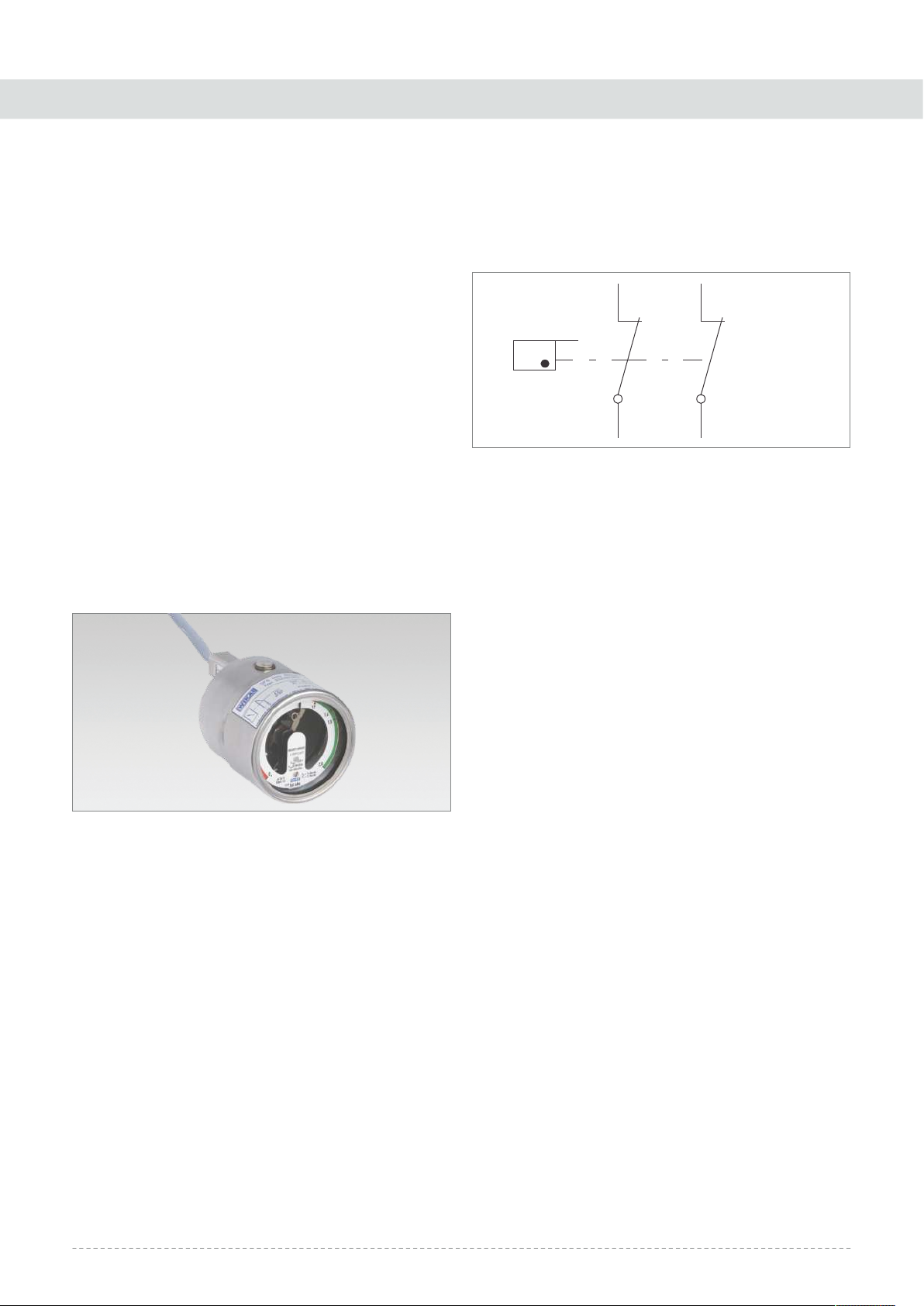
Let us consider switching contacts are normally closed
(NC). The terminal number details are as shown in
gure 3.3.2 :
When gas pressure inside tank is more than 1.25 Kg/cm² then
these two contacts shall be open.
1. When gas pressure decreases to less than 1.25 Kg/cm²,
contact with terminal no. 3-4 becomes Close. This contact
can be used to give an alarm, so that gas can be relled
before gas pressure falls to minimum permissible pressure.
When the gas is relled and the internal pressure exceeds
1.25 Kg/cm² then the switch is automatically reset (becomes
open).
2. When gas pressure decreases to less than 1.20 Kg/cm²,
contact with terminal no. 1-2 becomes Close. This contact
can be used to trip VCB. When the gas is relled and the
internal pressure exceeds 1.20 Kg/cm² then the switch is
automatically reset (becomes open).
Note: The switching point is not adjustable
3.4 - PRESSURE RELIEF DISC
The bursting disc is located on the rear of the breaker chamber
of every panel. For the bus compartment, it is located at the top
rear with an arcing chute for the main busbar direct arcing
produced to the rear. When the gas pressure in the
compartment exceeds 3.5kg/cm² during an arc fault, this disc
will burst.
MOLECULAR SIEVES
For proper working condition of the SF6 insulated switchgear,
the moisture content of the gas must be kept below 150ppm.
Condensation within the gas compartment is taken care of by
the molecular sieve, which absorbs moisture.
3.4.1 - GAS FILLING
During operation or lifetime of the equipment it may happen
that there is leakage in the tank due to some unavoidable
circumstances and the pressure on the SF6 manometer on the
Figure 3.3.1 - Gas pressure monitor (model 233.52.063)
Figure 3.3.2 - Normally closed switching contacts
1
2
3
4
SF6 GAS
LIMIT S/W

Operation & Maintenance Manual 06
STRUCTURAL DETAILS & GENERAL ARRANGEMENT
panel may start dropping and may fall to 1.25 bar. In this case
the operator needs to shutdown the panel and has to check it
for leakage. Once the leakage is identied and is welded, air is
lled in the panel to check, if the weld has removed the leakage
and there is no further leakage, after which the SF6 gas is lled
in the equipment at a desired pressure of 1.35 bar. The detailed
procedure for Vacuuming and Gas lling is provided in
Annexure-A. After the gas lling is completed the Power
Frequency Withstand Test should be done at sight.
Note: For quality and purity of SF6 gas refer the quality
certicates of the producers and manufacturers of SF6.

Operation & Maintenance Manual 07
HANDLING AND STORAGE
4.0 HANDLING AND STORAGE
4.1 - Precautions to be taken care
4.1.1 - Safety Aspects
The Switchgear panels are designed for Indoor Application
with all required safety features.
Before carrying out any installation, operation and
maintenance, the service person should be fully acquainted
with the relevant safety regulations covering this equipment
as well as with the inside of the substation.
Check that the personnel operating the apparatus have this
instruction manual with them.
We recommend that installation and commissioning should
be carried out by qualied and authorized personnel.
Ensure compliance of local (site) legal and safety norms.
4.1.2 - Unloading & Transportation
The switchgear panels are dispatched in appropriate
packaging for the prevailing conditions, e.g. seaworthy
packaging.
Unloading of Panels shall be done as per Instruction stickers
given on Panels.
Panel shall be unloaded with sufcient capacity of crane or
Hydra. If unloading is done with wire ropes, t lifting ropes of
appropriate load capacity with shackles and ensure that
lifting hooks are locked properly.
Transport switchgear panels upright only. Carry out loading
operations only when it has been ensured that all
precautionary measures to protect personnel and materials
have been taken and using a
- crane,
- fork-lift truck and/or
- manual trolley jack
Never tilt the crates over as shown below. Non Compliance
with this stipulation may damage the equipment. Always
keep it upright.
4.2 - PACKING AND UNPACKING
4.2.1 - Shipping Condition
The GIS panel is packed in the following crates.
1) Cubicle Body - In principle, 1 to 4 cubicles in one packing
2) Foundation framework and fastening bolts.
4.2.2 - Precautions for Unpacking
Upon arrival at site, the consignment shall be unpacked
within one (1) week and checked against the packing list or
the delivery note.
While unpacking wooden cases, top must be removed rst.
It is advisable to locate the switchgear at the sub-station
before unpacking. (THE EQUIPMENT SHOULD BE EXAMINED
IMMEDIATELY AFTER THE RECEIPT.)
In case of shortage in supply or damage to the items, report
the same within two (2) weeks, accompanied with a full
description/ photographs of the missing/damaged parts. Any
delay in making the claims will not be entertained.
TOP KEEP DRY LIFTING
ARRANGMENT
Figure 4.1.2 - Crate Positioning

Operation & Maintenance Manual 08
HANDLING AND STORAGE
4.3 - Transport and Handling
The following precautions should be taken in moving the
unpacked GIS.
4.3.1 - Precautions for Moving
The equipment may be moved either by suspending it with a
lifting apparatus or by hauling with lifting trucks. The following
precautions should be observed.
1) The channel on the ceiling of the cubicle may be
used for transport by cranes. The lifting rope angle at the
hook should not be more than 120 degrees. Rope with
appropriate strength to be used.
2) When the equipment is hauled on manual lifting truck, be
sure that the pallet is of sufcient loading capacity.
Furthermore, do not lower the cubicle on its edge as this may
result in mechanical damage. The cubicle is provided with a
transportation channel base to accommodate the fork of the
pallet truck.
3) Rollers may be used for single units of single bus cubicles.
Use rollers more than 2.0 meter long with equal diameters.
Move the cubicle carefully so that it will not tip over.
Figure 4.3.2 - Using Roller To Move CubicleFigure 4.3.1 - Liing The Cubicle
CRANE CRANE

Operation & Maintenance Manual 09
HANDLING AND STORAGE
4.4 - STORAGE
The type of packing depends on the duration and nature of
storage.
The standard cubicle packing is meant for indoor storage where
there is no possibility of condensation. If the equipment after
being unpacked is to be left as it is or stored for some period of
time until the installation commences or the equipment after
having been installed is left idle, the cubicle should be covered to
avoid contamination of dust on cubicle surface.
The switchgear is meant for indoor operation and should be
stored in a clean, dry and well-ventilated environment.
The storage area must shelter the equipment from
deterioration by agents like
- Water
- Water Vapour
- Salt Laden air
- Pollution of any type
- Micro-organisms
Store switchgear panels standing upright
Do not stack switchgear panels.
Switchgear panels are not weather-proof and should not be
left outdoor where rain and moisture may cause irreparable
damages.
For temporary indoor storage for less than two (2) weeks,
cover the switchgear with plastic sheets to protect it against
ingress of dust.
Do not walk on the roof of the panels.
4.4.1 - Intervention Levels
Definition
Level
Operations carried out by the client
Operations requiring training and which can be performed by an approved third party
Work which can only be carried out by E&A
1
2
3
Figure 4.4 - Storage Conditions

Operation & Maintenance Manual 10
HANDLING AND STORAGE
Wrapped under plastic Film
X X X
X X
X X
X X
-
-
-
Packaging should be periodically inspected
When the equipment is unpacked
10-12 times manoeuvres should be carried out in order to check the mechanical
operation of the equipment
The minimum threshold (85% of Un) of the coil electrical operation should be tested
2 31
4.4.2 - Special Instruction for a storage period between 0 and 6 months
Wrapped under heat sealing cloth with desiccant bags
Packaging should be periodically inspected (absence of any perforation amongst others)
When the equipment is unpacked : -
slightly dilute the dry greases with neutral paraffin oil
10-12 times manoeuvres should be carried out in order to check the mechanical
operation of the equipment
The minimum threshold (85% of Un) of the coil electrical operation should be tested
X X X
X X
-
X X
-
X X
-
123
4.4.3 - Special Instruction for a storage between 6 and 12 months period
4.4.4 - Special Instructions for a storage period between 12 and 24 months
-
-X
-
X X X
X X X
123
Wrap under heat sealing cloth with inspection doors to change the
desiccant bags
Packaging should be periodically inspected (absence of any perforation amongst others)
The desiccant bags should be regularly changed
When the equipment is unpacked : -
Visual Inspection should be performed
The minimum threshold (85% of Un) of the coil electrical operation should be tested
X-

Operation & Maintenance Manual 11
INSTALLATION
5.0 INSTALLATION
5.1 - Checks Prior to Installation
Check the order of cubicle arrangement, quantity and external
dimensions of the cubicle and base frame according to the
drawing provided (Refer gure 5.2 a).
5.2 - Foundation Work
Hack out the oor cement surface out to a level of 50mm below
the oor level. The framework is then seated on the sunken oor
and is anchored to the oor by angle iron brackets. If the panels
are factory coupled with base frames then it can be also xed on
at oor and channels.
Adjustment on the M12 anchor bolts is required to level the
frame on which the switchgear is to be installed. Leveling must
be done with an accurate level gauge. If not level, the GIS
switchboard may be distorted, leading to eventual failure of the
installed equipment. Please ensure that panel base frame and
base frame in nished oor level shall be matched. Both the base
frame or base frame and channel shall be bolted or tag welded.
Installation should be done in the following order so that the
level errors are within an allowable range.
Figure 5.2 a - Base Frame
Figure 5.2 c - Base Frame
Figure 5.2 b - Base Frame
1600 / 1800
400
233
4 : M12
115
52 52
40
140
593
233
4 : M12
52 52
40
140
1600 / 1800
115

Operation & Maintenance Manual 12
200 100
100 350
250.4
50
600600
DEPTH OF THE PANEL (TYPICAL 1400)
100 x 50 x 6 ISMC
200 100
100 350
DEPTH OF THE PANEL (TYPICAL 1400)
600 600
REAR PANEL
FIN.FL.LVL
CEMENT FILLING
FOR LEVELING
WITH FINISHED
FLOOR LEVEL
1400
350 200 100
52 74
75 X 125 X 6
EDGE ANGLE
50 X 100 X 6
ISMC
PANEL
ALONGWITH
BASE FRAME
FRONT
FIN. FL. LVL
FLOOR OPNG. FOR
CONTROL CABLE
FLOOR OPNG. FOR
POWER CABLE
SIDE VIEW
TOP VIEW WITH
ONLY CROSS CHANNEL
INSTALLATION
Figure 5.2 c - Top view with panel on Frame & Cross Channel

Operation & Maintenance Manual 13
INSTALLATION
5.2.1 - Order of Arrangement
1) The unit of the foundation frame is for one to four cubicles.
The frame can be combined for a larger housing. Any
jointing of the framework must be done only after the
leveling of both the frames is satisfactory as detailed in
Clause 5.2.2 and the frames are horizontally aligned as in
Clause 5.2.3.
2) The installation of foundation frame should begin at the
center of the cubicle array, moving progressively toward the
left and right side gure 5.2.2 a.
3) Fastening between the cubicle and the foundation frame is
done at four prepunched locations for each cubicle. The
foundation frame is supplied with M12 foundation bolts.
5.2.2 - Leveling Errors During Installation
The foundation frame should be installed so that the level
errors of installed bases fall within the range shown in
gure 5.2.2 a & b.
1) Front View of Foundation Frame.
L: Length of frame in the
cubicle width direction.
H: Height from the level reference point to the upper surface
of the frame to be installed rst
H+1mm
Figure 5.2.2 a - Level errors (front view)
REFERENCE
POINT
CHANNEL BASE TO
BE INSTALLED FIRST
H3 H1 H2
L
HI: Height difference between the frames arranged in the
cubicle width direction ....H1 = <0.5 mm
H2: Height difference between the left and right ends of one
frame.
H3: Height difference between the left and right ends of
another frame.
H2 < 1 mm when L < 3,000 mm
* H2 + H3 < 2 mm when the frames are arranged in the
cubicle width direction.
F: Exposed height from the oor surface to the upper surface of
the frame ..F < 2
2) Side View of Foundation Frame.
H4: Height difference between front and rear frames
.H4 < 2mm.
Figure 5.2.2 b - Level errors (side view)
H4

Operation & Maintenance Manual 14
INSTALLATION
5.2.3 - Horizontal Deviations
Horizontal deviations of frames in the lateral and longitudinal
directions should be within the range shown in gure 5.2.3.
A: Distance from the reference point to the cubicle installation
start point
......................A < 1 mm
B: Distance from the reference point to the front side of the
frame
......................B < 1 mm
C: Longitudinal deviation (in the front and back direction)
between the frames arranged in the cubicle lateral direction
......................C < 1 mm
D: Gap between the laterally arranged, adjacent frames
......................D < 1 mm
Figure 5.2.3 - Longitudinal deviations (top view)
5.2.4 - Foundation Frame
After the foundation frame installation is completed, ll the
hollowed oor around the perimeter of the frame with cement
as in gure 5.2.4.
5.3 - Cubicle Installation
5.3.1 - Location of Fastenings
GIS is divided into unit cubicles. Parts (bolts, nuts, etc) used for
installation are packed in a vinyl bag with a tag and attached to
the cubicle body.
5.3.2 - Order of Installation
1. Draw cubicle reference line on the foundation frame.
These reference lines will serve a guide for more
accurate alignment of the cubicle.
2. Remove the transportation bolt on the top of the cubicle.
3. Remove the top gas duct from all panels.
4. Locate the rst panel onto the center position with the aid
of a preferable hydraulic jack, making sure that its front
base channel is aligned to the reference line. If the
alignment is good, the four foundation bolts can be quite
easily inserted into the framework holes.
Figure 5.2.4 - Cement Filling
FOUNDATION
FRAME
CEMENT MUST BE SAME
LEVEL WITH THE FRAME
TRENCH
BASE TO BE
INSTALLED FIRST
REFERENCE
POINT
A
BD
INSTALLATION
START POINT
C
FRONT SIDE
OF CUBICLE

Operation & Maintenance Manual 15
INSTALLATION
Dos:
1. Floor levels are clean and ensure there should not be any
hardware / small equipments below the panels.
2. Check all the components received are in proper condition.
3. Please refer O&M Manual for oor leveling.
4. Clean the panels using lint free cloths provided.
5. Use preferred Contact grease HBK83-102 as mentioned.
6. Use MOLYKOT 111 Compound/FOMBLIN GRM60 for
sealing purpose.
7. Use proper setting of torque wrench for tightening
hardware.
8. During panel movement ensure that copper rod, guiding pin
and lead screw are engaging properly.
9. Ensure all the hardwares are tightened properly.
10. Ensure all three B/B Plug-in conductor main are xed in the
panel during coupling only.
11. Ensure for equivalent movement of the panel from top and
bottom levels during coupling.
12. Ensure Earthing spring cord of all B/B Plug-in are properly
xed with the plate using M5 screw size.
13. Ensure the Arc Release Ducts chamber are not xed with the
panel during panel movement and coupling.
14. Keep proper vision and attention on the B/B Plug-in
conductor main alignment during coupling.
15. Check the alignment of earth bar during coupling of panels.
Donts:
1. Handling of components without hand gloves.
2. Misalignment of bushings & busbar.
3. Using additional force during coupling (use only lead screw
or hydraulic jack as mentioned in O&M manual).
4. After applying MOLYKOT 111 Compound/FOMBLIN GRM60
to silicon plug, Dont Keep open to atmosphere more than
half an hour.
5. Fix B/B Plug-in conductor main with the panel during panel
movement.
6. Leave the B/B Plug-in conductor main with the panel after
xing it.
7. Leave the Earthing Spring Cord in hanging condition.
5.3.5 - Connecting the Earthing Bus
The earthing bus is provided at the lower back of each cubicle.
After the cubicle and busbar coupling is completed, connect the
earthing buses. The GIS is divided into unit cubicles as shown in
gure 5.3.5 and the earthing bus is likewise divided at the same
positions.
1) The earth terminal is provided at the left-end unit of the
cubicle array. Draw out the earthing wire from here.
2) Determine the earthing wire drawout position according to
the separate GIS oor plan.
3) The earthing wire should have a minimum of 180mm²
stranded bare hard copper wire.
4) Cable earthing shall be done on holes provided on earth bar.
5.4 - Connecting Control Wiring
1) The multicore cable termination for the control cable is
provided at the front on the right side. Connection should be
Figure 5.3.5 - Assembly of The Earthing Bus
Earth Bar
Connection
of Earth Bar
Between
2 Panels

Operation & Maintenance Manual 16
INSTALLATION
made according to the connection diagram given.
2) For CTs in buscoupler panel inside tank CT secondary
bushing connections are given in respective LV panel as
shown in Figure 5.3.6.
Precautions:
The terminals must be tightly, fastened.
Check the tightness of all terminals before energizing.
5.5 - Connecting Power Cable
Termination and connection of the power cable should follow
the instructions of cable termination manufacturer.
If CTs are mounted on bushing no need to remove CTs during
cable termination.
Terminate power cable into bushing. Ensure correct phase co-
ordination. Insert termination cables into sockets located at the
rear compartment and secure with screws. Align cable and
support cables properly to avoid tension.
The procedure for xing the gland plate is as below:
a) The gland plate can be cut into two for easy installation.
b) Measure the diameter of the cable.
c) Cut a semicircle on each half of the gland plates to match the
cable diameter.
d) Adjust the position of the power cable and mount the cable
gland plates onto the welded studs at the cubicle base plate.
Tighten the nuts securely.
e) If there is any gap between the power cables to ll the gap
with sealing compound.
f) The Cable screen should be properly connected to the panel
earthing.
Note: Connect only one end of the cable earth and not both. For
single core cables, there should be a gap between the split plates
and the same to be sealed with compound. This is to prevent
eddy current circulation.
5.6 - Inspection after Installation
5.6.1 - General Inspection
1) Check that the door can be smoothly opened and closed.
2) Make sure that the bolts and nuts that were tightened during
installation are not loose.
3) Factory-tightened bolts and nuts are torque-marked with a
red paint. Check that the marks on these fastenings are not
shifted.
4) Check that the earthing bars are correctly connected and that
the earth is connected at one point to the substation
earthing.
5) Inspect all protection relays and meters. Remove shipping
stops, if any.
6) Check the connection for control wiring.
7) Clean complete panel from inside and outside.
Figure 5.3.6 - Bus coupler CT secondary bushing terminals
1S1 1S2
2S1 2S2
E
3S1 3S2
R
YB

Operation & Maintenance Manual 17
COMMISSIONING
This section is a guide to the minimum checks and tests that
should be performed on site prior to energising the equipment.
6.1 - PRELIMINARY CHECKS
Preliminary inspections should be carried out prior to the
connection of the high voltage supply:
1) Check the mechanical and electrical interlocks for correct
operation.
2) Check that the switchboard is earthed to the station
earthing.
3) Check the gas monitors for correct operating pressure
within the green zone.
4) Check that the control power is on.
5) Conduct a primary current injection on the protection relay
to ensure functional operation with proper test set.
6) Perform a dielectric test on the power cables to appropriate
standards.
7) Conduct an operational test on the panel's control and
protection system.
8) Check the general condition of the switchboard for any
abnormalities that will affect operations.
9) Check external equipment such as remote controls, auxiliary
power source and substation condition.
6.2 - TESTING
On site test for the gas-lled compartments should include the
following:
a) Hipot test of the main circuits. (PT should be isolated from
the main circuit before test)
b) Moisture content of gas one day after gas lling.
c) Contact resistance & Insulation resistance
d) Current Injection on Primary & Secondary Circuit
6.3 - START-UP
1) During start-up, safety regulations should be observed.
2) Ensure that all the switch-disconnectors and circuit breakers
are in off position.
3) Remove any connecting or shorting links used during the
preliminary tests.
4) Energise the switchboard step-by-step, observing all signals
and indicators.
5) Watch for any abnormalities.
6.4 - SWITCHING OPERATIONS
6.4.1 - POSITION ISOLATION
The 3-position disconnecting switch selects one of three
positions-ON, OFF and Earth by a pair of blades.
The cable side may be earthed through the circuit breaker. It can
be electrically and mechanically interlocked with an associated
circuit breaker. For details, refer to the relevant instruction
manual.
Manual operation: Please refer to the attached manual (and the
caution plate on the operating device). for the operation of the
Disconnecting Switch.
Electrical operation: As a precaution for electrical operation, the
manual operation handle must be OUT. After the interlock is
cancelled, turn the handle of the Disconnect or control switch on
the front door panel. Only one disconnecting switch can be
operated at any one time.
This section is a guide to the minimum checks and tests that
should be performed on site prior to energising the equipment.
6.4.2 - Interlocks between VCB and 3-Position
Disconnecting Switch.
The disconnecting switch cannot interrupt load current. Hence,
the switch can only be operated when the breaker is OFF.
When the breaker is ON, the mechanical and electrical interlocks
prevent the disconnecting switch from being operated.
In addition, closure of breaker is not possible when the
disconnecting switch operation is in progress. Operation of the
switches or breaker is not possible with the shutter of the switch
opened.
PRECAUTION: The interlock system may differ from case to
case. Refer to the operating system in the schematic drawings.
6.4.3 - Circuit Breaker Operation
Manual operation: Refer to the Breaker Installation Manual and
the caution plate of the operating device for the operation of the
breaker.
Electrical operation: Turn the local breaker control switch (TNC)
6.0 COMMISSIONING

Operation & Maintenance Manual 18
COMMISSIONING
handle on the front door panel to OFF or ON or remotely switch
the breaker. The status of the device can be checked with the
indicators located at the front door.
6.4.4 - Earthing of Bus and Switches
An interlock allows the bus to be earthed when all the feeder
switches are disconnected from the bus (Dead Bus Check).
This is to ensure the respective bus is dead before earthing.
Motorised version of the earth switch is provided as standard
package.
Before earthing operation switch the local remote switch to local
mode.
Do not trip the breaker electrically when disconnector
switch is in earth position.
Any special interlocks for earthing operations will be shown in
the technical project drawings.
6.5 - Safety interlocks in GIS Switchgears
Following Interlocks are provided in GIS switchgear for safety
purpose during operation & maintenance :-
1. Mechanical & Electrical interlocks prevent the operation of
disconnector switch, when the breaker is ON.
2. Disconnector switch can be operated only when VCB is off.
3. Closure of VCB is not possible when the disconnector switch
is in operation.
1. VCB / Disconnector Switch
Isolator can be operated only when VCB is in OFF
condition. The selector position is padlockable.
VCB cant be operated, either mechanically or electrically,
when Isolator is accessed.
2. Permissive Earth
Feeder: Bus Coupler & Riser
Premissive Earth (PE)
1. In normal condition key will not be available in PE lock.
2. To operate DS from OFF to Earth position key has to be
trapped in PE lock.
3. Key will be trapped in lock till DS is in Earth position.
Sequence of operation for BUS-A Earthing
1. To Earth power cable, key has to be trapped in PE lock.
2. Key suitable for PE lock shall be made available only with
authorized person. Authorized person will issue the key only
after ensuring that BUS-A is dead.
3. Trap the key in PE lock provided at riser panel and move DS of
riser to Earth postion.
4. Earth BUS-A by making DS and breaker of BUS coupler ON.
Sequence of operation for BUS-B Earthing
1. To Earth power cable, key has to be trapped in PE lock.
2. Key suitable for PE lock shall be made available only with
authorized person. Authorized person will issue the key only
after ensuring that BUS-B is dead.
Figure 6.4.4 - DS Facia
4. At a time, Disconnector switch can be operated either
electrically or mechanically but not simultaneously.
5. Closure of VCB is not possible unless the spring is fully
charged.
Figure 6.4.5 - Bus Coupler & Riser
BUS-A BUS-B
Q1
DISCONNECTOR
SWITCH
1250A
Q1
DISCONNECTOR
SWITCH
1250A
Q0
VCB
1250A
PE PE
KEY FROM
AUTHORIZED
PERSON
KEY FROM
AUTHORIZED
PERSON
EARTH
EARTH
OFF
OFF ON
ON
Lock & Key Qty Details
PE: 1 Lock & 1 Key
CABLE
ACCESS
DS
OPERATION
This manual suits for next models
12
Table of contents
Popular Industrial Electrical manuals by other brands

Murata
Murata GRM1887U1H103JA01 Series Reference sheet

Schrack
Schrack LTZ40002 Series instruction manual

Murata
Murata GRM186R60G226ME15 Series Reference sheet

Murata
Murata GRM1885C1H681JA01 Series Reference sheet

Softing
Softing FG-200 HSE/FF user manual

Murata
Murata GRM188R7YA105KA12 Series Reference sheet