Laney CONCEPT 6 User manual

Laney
Series Mixing Consoles
Concept 6
Concept 8
USER MANUAL

Concept
Concept Manual
22
TABLE OF CONTENTS
Concept 6 - Concept 8
User Manual
Page 4Page 4
Page 3Page 3
Page 2Page 2 ContentsContents
General InformationGeneral Information
Concept 6/8 Quick Start GuideConcept 6/8 Quick Start Guide
Concept 6/8 Quick Start DiagramsConcept 6/8 Quick Start Diagrams
Concept 6/8 FeaturesConcept 6/8 Features
Mic/Line Channel InformationMic/Line Channel Information
Mic/Line channel information (cont)Mic/Line channel information (cont)
Graphic Equaliser/DigiFx InformationGraphic Equaliser/DigiFx Information
Concept 6/8 Block DiagramsConcept 6/8 Block Diagrams
Concept 6/8 Technical SpecificationsConcept 6/8 Technical Specifications
Rear panel detailsRear panel details
Masters InformationMasters Information
Page 5Page 5
Page 6Page 6
Page 7Page 7
Page 8Page 8
Page 9Page 9
Page 10Page 10
Page 11Page 11
Page 12Page 12
Page 13Page 13
Page 14Page 14

Concept
Concept Manual
33
We at Laney are extremely pleased that you have decided to select a Concept mixing
desk for your mixing and we wish to reinforce your judgement by ensuring you get off to
a flying start by including this comprehensive user manual to assist you in getting to
know your equipment.
Before switching on please read this manual carefully since whilst you may well be an
experienced user no two brands are the same, and on reading this manual you will
become aware of the subtle advantageous differences that Concept offers over its
UNPACKING
On unpacking your Concept please check carefully for any signs of damage that may have
occurred whilst in transit from the Laney factory to your dealer. In the unlikely event that
there has been damage please repack your unit in its original carton and consult your
dealer.
We would strongly advise you to store away your original transit carton since in the unlikely
event that some time in the future your unit should develop a fault, you will be able to
return it to your dealer for rectification securely packed.
Your mixer should be fitted with a three pin 'grounded' (or 'earthed') plug. Please make
sure that the mixer is powered from a 'grounded/earthed' outlet.
If changing or fitting a plug yourself, ensure that the applicable wiring code is adhered to,
for example in the UK the cable colour code for connections are as follows:
The mixer should never be exposed to moisture or wetness under any circumstances since
this would represent a possible shock or fire hazard, and may cause expensive damage to
your valuable possession.
In the unlikely event that a fuse should blow, it is imperative that you or your engineer, use
a correctly rated replacement.
Details of the fuse required is printed on the rear panel of the mixer, please take special
care to use a 'time delay' fuse wherever stated.
THANK YOU
IMPORTANT SAFETY INFORMATION
EARTH OR GROUND
NEUTRAL
LIVE
GREEN/YELLOW
BLUE
BROWN

Concept
Concept Manual
44
SPECIAL FEATURES
Laney have been established in audio
amplification for over twenty five years, during
which time it has firmly established itself as a
benchmark for audio products.
Feedback from musicians and recording
engineers, supported by original design ingenuity,
are the parameters applied by Laney's
development engineers to all new products.
Concept mixers explained within this manual are
easy to use but incorporate features which make
advanced set ups easy in any role.
Sub-mixing - Main P.A. - Monitors
The mixer in this manual have a combination of
Mic/line inputs and Mic/Stereo channels for extra
flexibility.
6 Mic/Line channels Concept 6
8 Mic/line channels Concept 8
2 * 150 Watt Output Power
2* 100 Watt Output Power
6 Band Graphic EQ
On Board Digital Reverb
(Concept 8)
Phantom Power
3 Band EQ
Mon/Digifx sends
Pfl facilities
+10+10
OdBOdB
-6-6
-10-10
-20-20
-30-30
+6+6
--
88
PREPRE
(POST)(POST)
(POST)(POST)
EQEQ
FXFX
1010
99
88
77
66
55
44
33
22
11
00
PANPAN
55
44
33
22
11
00
11
22
33
44
55
00
11
22
33
44
55
66
77
88
99
1010
55
44
33
22
11
00
11
22
33
44
55
55
44
33
22
11
00
11
22
33
44
55
55
44
33
22
11
00
11
22
33
44
55
1010
99
88
77
66
55
44
33
22
11
00
GAINGAIN
HFHF
MIDMID
LOLO
MONMON
PFLPFL
+10+10
OdBOdB
-6-6
-10-10
-20-20
-30-30
+6+6
--
88
+10+10
OdBOdB
-6-6
-10-10
-20-20
-30-30
+6+6
--
88
PREPRE
(POST)(POST)
(POST)(POST)
EQEQ
FXFX
1010
99
88
77
66
55
44
33
22
11
00
PANPAN
55
44
33
22
11
00
11
22
33
44
55
00
11
22
33
44
55
66
77
88
99
1010
55
44
33
22
11
00
11
22
33
44
55
55
44
33
22
11
00
11
22
33
44
55
55
44
33
22
11
00
11
22
33
44
55
1010
99
88
77
66
55
44
33
22
11
00
GAINGAIN
HFHF
MIDMID
LOLO
MONMON
PFLPFL
DIGITAL FXDIGITAL FX
PFLPFL
00
11
22
33
44
55
66
77
88
99
1010
PEAKPEAK
INPUT INPUT
PROGRAMPROGRAM
TIMETIME
MONMON
ShortShort
LongLong
HallHall
Dark HallDark Hall
RoomRoom
Dark RoomDark Room
PlatePlate
Dark PlateDark Plate
Delay RegenDelay Regen
Reverse ReverbReverse Reverb
LEVELLEVEL
Gated ReverbGated Reverb
DelayDelay
00
11
22
33
44
55
66
77
88
99
1010
11
22
33
44
55
66
88
77
11
MICMIC
11
PADPAD
MIC/LINEMIC/LINE
LINELINE LINELINE
MIC/LINEMIC/LINE
PADPAD
22
MICMIC
22
LINELINE
MIC/LINEMIC/LINE
PADPAD
33
MICMIC
33
LINELINE
MIC/LINEMIC/LINE
PADPAD
44
MICMIC
44
LINELINE
MIC/LINEMIC/LINE
PADPAD
55
MICMIC
55
LINELINE
MIC/LINEMIC/LINE
PADPAD
66
MICMIC
66
LINELINE
MIC/LINEMIC/LINE
PADPAD
77
MICMIC
77
LINELINE
MIC/LINEMIC/LINE
PADPAD
88
MICMIC
88
Concept 8Concept 8
+10+10
OdBOdB
-6-6
-10-10
-20-20
-30-30
+6+6
--
88
+10+10
OdBOdB
-6-6
-10-10
-20-20
-30-30
+6+6
--
88
+10+10
OdBOdB
-6-6
-10-10
-20-20
-30-30
+6+6
--
88
LEFTLEFT
RIGHT/PFLRIGHT/PFL
OdBOdB
-3dB-3dB
-6dB-6dB
-9dB-9dB
+6dB+6dB
+3dB+3dB
-21dB-21dB
-18dB-18dB
-15dB-15dB
-12dB-12dB-12dB-12dB
-15dB-15dB
-18dB-18dB
-21dB-21dB
+3dB+3dB
+6dB+6dB
-9dB-9dB
-6dB-6dB
-3dB-3dB
OdBOdB
LEFTLEFT
MASTERSMASTERS
RIGHTRIGHT
PFLPFL
ACTIVEACTIVE
LaneyLaney
PHONESPHONES
HEADHEAD
TAPETAPE
TAPETAPE
00
11
22
33
44
55
66
77
88
99
1010
TO MONTO MON
FADERFADER
MONOMONO
RIGHTRIGHT
LEFTLEFT
TAPE INPUTTAPE INPUT
STEREO AUXILIARY INPUTSSTEREO AUXILIARY INPUTS
LEFTLEFT
RIGHTRIGHT
STEREOSTEREO
1010
99
88
77
66
55
44
33
22
11
00
MONMON
MONMON
00
11
22
33
44
55
66
77
88
99
1010
1010
99
88
77
66
55
44
33
22
11
00
TO MASTERTO MASTER
FXFX
1010
99
88
77
66
55
44
33
22
11
00
TAPE OUTPUTTAPE OUTPUT
HEADPHONE LEVELHEADPHONE LEVEL
600Hz600Hz
1K2Hz1K2Hz
3KHz3KHz
10KHz10KHz
10KHz10KHz
3KHz3KHz
1K2Hz1K2Hz
600Hz600Hz200Hz200Hz
80Hz80Hz
STEREO GRAPHICSSTEREO GRAPHICS
200Hz200Hz
80Hz80Hz
POWERPOWER
PHANTOMPHANTOM
0dB0dB
+8dB+8dB
-8dB-8dB
+8dB+8dB
-8dB-8dB
0dB0dB
+10+10
OdBOdB
-6-6
-10-10
-20-20
-30-30
+6+6
--
88
PREPRE
(POST)(POST)
(POST)(POST)
EQEQ
FXFX
1010
99
88
77
66
55
44
33
22
11
00
PANPAN
55
44
33
22
11
00
11
22
33
44
55
00
11
22
33
44
55
66
77
88
99
1010
55
44
33
22
11
00
11
22
33
44
55
55
44
33
22
11
00
11
22
33
44
55
55
44
33
22
11
00
11
22
33
44
55
1010
99
88
77
66
55
44
33
22
11
00
GAINGAIN
HFHF
MIDMID
LOLO
MONMON
PFLPFL
+10+10
OdBOdB
-6-6
-10-10
-20-20
-30-30
+6+6
--
88
+10+10
OdBOdB
-6-6
-10-10
-20-20
-30-30
+6+6
--
88
PREPRE
(POST)(POST)
(POST)(POST)
EQEQ
FXFX
1010
99
88
77
66
55
44
33
22
11
00
PANPAN
55
44
33
22
11
00
11
22
33
44
55
00
11
22
33
44
55
66
77
88
99
1010
55
44
33
22
11
00
11
22
33
44
55
55
44
33
22
11
00
11
22
33
44
55
55
44
33
22
11
00
11
22
33
44
55
1010
99
88
77
66
55
44
33
22
11
00
GAINGAIN
HFHF
MIDMID
LOLO
MONMON
PFLPFL

Concept 6/8 Quick Start Guide
This is a quick start guide so you can be using you mixer sooner rather than later - you can
then refer to the detailed description later in this manual when you need.
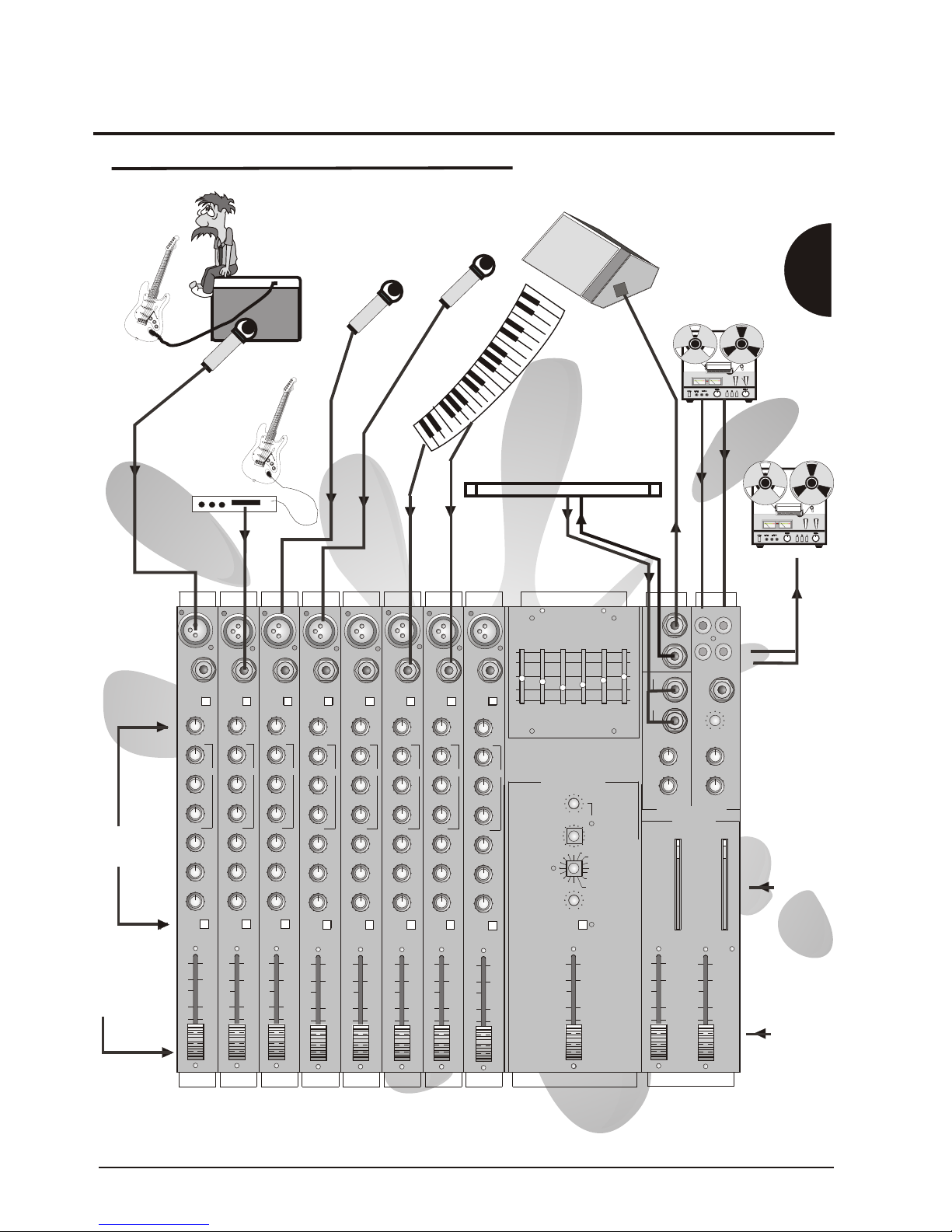
2 diagrams are provided to supplement this information following these tips
Plugging in !
Connect power to your mixer - always a good start !
Switch On -
Connect all you input signals Mics/DI's/Keyboards/Tape machines to there relevant input
channels
Connect your condenser Mics before enabling Phantom power
**Do not connect dynamic Mics or unbalanced sources to mic inputs when Phantom power is
enabled otherwise damage may occur to your them or your mixer**
Its a good idea to label up each channel strip, so you know what is connected where - this can
be done in chinagraph in the `write on' areas or use a piece of masking tape along the front
edge of the mixer (the old favourite)
Its always good practice to start work on mixer with all gain controls at minimum ,all faders at
minimum and all EQ set flat.
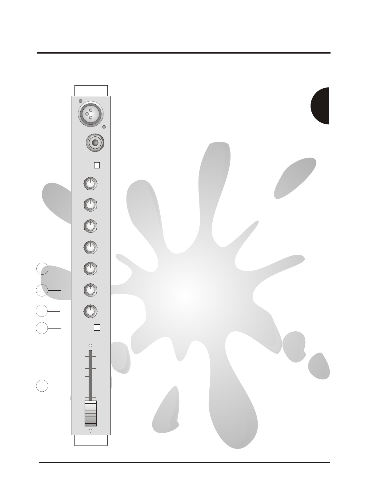
Input Channel
Do not be intimidated by the input channels on your mixer as it's function is very simple:-
1)The gain control - makes little signals big, so they are as far above noise as possible but not
so high that the signal is clipped - the peak led illuminates when clipping is near.
2)The EQ section - tonally changes the input signal , this is just like the tone controls on your
Hi -Fi but with more knobs. The controls are labelled-Hi , Mid(gain + Frequency) and Lo
controls
3)It lets you send the signal to places of use e.g. A Monitor send for a vocalists/Musician
Aux 1 and Digifx if you want to add echo/reverb to a signal. These send controls are labelled
Mon, Aux 1 and Digifx
4)You can adjust the signals position in the stereo image using the Pan control.
5)Fader - this controls the signal level being sent to Masters
Setting the gain on an Input Channel
By now you will have connected your input signals to your mixer and be ready to set your input
gain controls.
1)Enable Pfl on the channel which you wish to set up - the right meter shows the signal level in
that channel and the channels signal appears on the headphones
2)Tell the vocalist/musician to play - while he plays you should set the channel gain control so
that 0dB to +6dB will illuminate on signal peaks
3)Increase the channel fader to between -10 and OdB and then increase the masters faders to
a level which is a satisfactory volume - power amp level control should be about -6db.
4)This point is a good time to set the EQ - remember if you boost a lot you will have to reset
the input gain control as described in 2)
FX
Certain instruments will benefit from the addition of some form of effect for instance snares can
be made sound `bigger' with the addition of a reverb or maybe a vocal could be thickened up
with a bit of delay.
Concept
Concept Manual
55

Concept
Concept Manual
66
You can send signals to FX using the Aux 1 and Digifx controls on the channels .
The Aux 1 master send control adjusts the overall level sent to external FX units via the
Aux 1 output socket . Signals from external FX units should be returned by the Stereo
auxiliary - a rotary fader is then used to control the level of FX signal sent to masters,
enabling a mix to established between FX signal and signal without FX
The Digifx control sends signals to the Digifx section. The input level control on the DigiFx
should be set so the Peak light in the DigiFx section is just prior to it illuminating, like the Stereo
auxiliary, a fader is provided to control the FX signal sent to the masters.
Time to mix
One way to do this is to increase all the input channels to approx. -10dB to 0dB.
Ask the band to play, Increase the master faders for to a satisfactory volume level.
Adjust the input channel faders so there level relative to other instruments sounds good - e.g.
the keyboard player does not sound louder than the lead vocalist.
You can also adjust the position of an instrument in the stereo image - e.g. to bring a vocalist
out in the mix, you could pan all other signals Left or Right by varying amounts.
A graphic equaliser is provided allowing the overall sound of your mix to be fine tuned .
Feedback
As you set up your mix you will probably have problems with feedback.
This occurs when microphones pick up sound from the loudspeakers creating a loud
whistling/howling sound - very disturbing
Here are a few ways to prevent this
1)make sure the sound from the speakers ,connected to your Mixers speaker outs, cannot be
picked up by microphones .( speakers are best in front + facing away from the band)
2)Keep the faders down on microphones which are not needed.
3)Try to cut rather than boost when using any EQ.
4)If feedback does occur use the channel EQ /graphic EQ to stop it, this can be done by cutting
at the frequency which the feedback occurs.
A feedback filter is provided on the monitor send
Recording
If you want to record your mix a tape out is provided to connect to tape/DAT/MD/DCC
machines. The line out / tape out level controls the level sent to the tape machine.
Finally................
Following this section follows more some quick set-up diagrams and more detailed information
about your Concept mixer's facilities.
Good luck with your mixing !

Concept
Concept Manual
77
CONCEPT 6 / 8 Quick Set Up Guide
+10+10
OdBOdB
-6-6
-10-10
-20-20
-30-30
+6+6
--
88
PREPRE
(POST)(POST)
(POST)(POST)
EQEQ
FXFX
1010
99
88
77
66
55
44
33
22
11
00
PANPAN
55
44
33
22
11
00
11
22
33
44
55
00
11
22
33
44
55
66
77
88
99
1010
55
44
33
22
11
00
11
22
33
44
55
55
44
33
22
11
00
11
22
33
44
55
55
44
33
22
11
00
11
22
33
44
55
1010
99
88
77
66
55
44
33
22
11
00
GAINGAIN
HFHF
MIDMID
LOLO
MONMON
PFLPFL
+10+10
OdBOdB
-6-6
-10-10
-20-20
-30-30
+6+6
--
88
+10+10
OdBOdB
-6-6
-10-10
-20-20
-30-30
+6+6
--
88
PREPRE
(POST)(POST)
(POST)(POST)
EQEQ
FXFX
1010
99
88
77
66
55
44
33
22
11
00
PANPAN
55
44
33
22
11
00
11
22
33
44
55
00
11
22
33
44
55
66
77
88
99
1010
55
44
33
22
11
00
11
22
33
44
55
55
44
33
22
11
00
11
22
33
44
55
55
44
33
22
11
00
11
22
33
44
55
1010
99
88
77
66
55
44
33
22
11
00
GAINGAIN
HFHF
MIDMID
LOLO
MONMON
PFLPFL
DIGITAL FXDIGITAL FX
PFLPFL
00
11
22
33
44
55
66
77
88
99
1010
PEAKPEAK
INPUT INPUT
PROGRAMPROGRAM
TIMETIME
MONMON
ShortShort
LongL ong
HallHall
Dark HallDark Hall
RoomRoom
Dark RoomDark Room
PlatePlate
Dark PlateDark Plate
Delay RegenDelay Regen
Reverse ReverbReverse Reverb
LEVELLEVEL
Gated ReverbGated Reverb
DelayDelay
00
11
22
33
44
55
66
77
88
99
1010
11
22
33
44
55
66
88
77
11
MICMIC
11
PADPAD
MIC/LINEMIC/LINE
LINELINE LINELINE
MIC/LINEMIC/LINE
PADPAD
22
MICMIC
22
LINELINE
MIC/LINEMIC/LINE
PADPAD
33
MICMIC
33
LINELINE
MIC/LINEMIC/LINE
PADPAD
44
MICMIC
44
LINELINE
MIC/LINEMIC/LINE
PADPAD
55
MICMIC
55
LINELINE
MIC/LINEMIC/LINE
PADPAD
66
MICMIC
66
LINELINE
MIC/LINEMIC/LINE
PADPAD
77
MICMIC
77
LINELINE
MIC/LINEMIC/LINE
PADPAD
88
MICMIC
88
Concept 8Concept 8
+10+10
OdBOdB
-6-6
-10-10
-20-20
-30-30
+6+6
--
88
+10+10
OdBOdB
-6-6
-10-10
-20-20
-30-30
+6+6
--
88
+10+10
OdBOdB
-6-6
-10-10
-20-20
-30-30
+6+6
--
88
LEFTLEFT
RIGHT/PFLRIGHT/PFL
OdBOdB
-3dB-3dB
-6dB-6dB
-9dB-9dB
+6dB+6dB
+3dB+3dB
-21dB-21dB
-18dB-18dB
-15dB-15dB
-12dB-12dB-12dB-12dB
-15dB-15dB
-18dB-18dB
-21dB-21dB
+3dB+3dB
+6dB+6dB
-9dB-9dB
-6dB-6dB
-3dB-3dB
OdBOdB
LEFTLEFT
MASTERSMASTERS
RIGHTRIGHT
PFLPFL
ACTIVEACTIVE
LaneyLaney
PHONESPHONES
HEADHEAD
TAPETAPE
TAPETAPE
00
11
22
33
44
55
66
77
88
99
1010
TO MONTO MON
FADERFADER
MONOMONO
RIGHTRIGHT
LEFTLEFT
TAPE INPUTTAPE INPUT
STEREO AUXILIARY INPUTSSTEREO AUXILIARY INPUTS
LEFTLEFT
RIGHTRIGHT
STEREOSTEREO
1010
99
88
77
66
55
44
33
22
11
00
MONMON
MONMON
00
11
22
33
44
55
66
77
88
99
1010
1010
99
88
77
66
55
44
33
22
11
00
TO MASTERTO MASTER
FXFX
1010
99
88
77
66
55
44
33
22
11
00
TAPE OUTPUTTAPE OUTPUT
HEADPHONE LEVELHEADPHONE LEVEL
600Hz600Hz
1K2Hz1K2Hz
3KHz3KHz
10KHz10KHz
10KHz10KHz
3KHz3KHz
1K2Hz1K2Hz
600Hz600Hz200Hz200Hz
80Hz80Hz
STEREO GRAPHICSSTEREO GRAPHICS
200Hz200Hz
80Hz80Hz
POWERPOWER
PHANTOMPHANTOM
0dB0dB
+8dB+8dB
-8dB-8dB
+8dB+8dB
-8dB-8dB
0dB0dB
+10+10
OdBOdB
-6-6
-10-10
-20-20
-30-30
+6+6
--
88
PREPRE
(POST)(POST)
(POST)(POST)
EQEQ
FXFX
1010
99
88
77
66
55
44
33
22
11
00
PANPAN
55
44
33
22
11
00
11
22
33
44
55
00
11
22
33
44
55
66
77
88
99
1010
55
44
33
22
11
00
11
22
33
44
55
55
44
33
22
11
00
11
22
33
44
55
55
44
33
22
11
00
11
22
33
44
55
1010
99
88
77
66
55
44
33
22
11
00
GAINGAIN
HFHF
MIDMID
LOLO
MONMON
PFLPFL
+10+10
OdBOdB
-6-6
-10-10
-20-20
-30-30
+6+6
--
88
PREPRE
(POST)(POST)
(POST)(POST)
EQEQ
FXFX
1010
99
88
77
66
55
44
33
22
11
00
PANPAN
55
44
33
22
11
00
11
22
33
44
55
00
11
22
33
44
55
66
77
88
99
1010
55
44
33
22
11
00
11
22
33
44
55
55
44
33
22
11
00
11
22
33
44
55
55
44
33
22
11
00
11
22
33
44
55
1010
99
88
77
66
55
44
33
22
11
00
GAINGAIN
HFHF
MIDMID
LOLO
MONMON
PFLPFL
PREPRE
(POST)(POST)
(POST)(POST)
EQEQ
FXFX
1010
99
88
77
66
55
44
33
22
11
00
PANPAN
55
44
33
22
11
00
11
22
33
44
55
00
11
22
33
44
55
66
77
88
99
1010
55
44
33
22
11
00
11
22
33
44
55
55
44
33
22
11
00
11
22
33
44
55
55
44
33
22
11
00
11
22
33
44
55
1010
99
88
77
66
55
44
33
22
11
00
GAINGAIN
HFHF
MIDMID
LOLO
MONMON
PFLPFL
+10+10
OdBOdB
-6-6
-10-10
-20-20
-30-30
+6+6
--
88
+10+10
OdBOdB
-6-6
-10-10
-20-20
-30-30
+6+6
--
88
PREPRE
(POST)(POST)
(POST)(POST)
EQEQ
FXFX
1010
99
88
77
66
55
44
33
22
11
00
PANPAN
55
44
33
22
11
00
11
22
33
44
55
00
11
22
33
44
55
66
77
88
99
1010
55
44
33
22
11
00
11
22
33
44
55
55
44
33
22
11
00
11
22
33
44
55
55
44
33
22
11
00
11
22
33
44
55
1010
99
88
77
66
55
44
33
22
11
00
GAINGAIN
HFHF
MIDMID
LOLO
MONMON
PFLPFL
connect
tape/DAT machine
here for recording
connect
tape/DAT machine
here for recording
connect tape/DAT/CD
here for playback
connect tape/DAT/CD
here for playback
connect Keyboards,
Synths etc here
connect Keyboards,
Synths etc here
Connect Vocals here
Connect Vocals here
Connect more Vocals here
D.I. your Guitar/
Bass here
D.I. your Guitar/
Bass here
o
oo
o
O O O O O FX PROCESSOR
FX output to FX unit input
FX unit output to Stereo Auxiliary Input
FX output to FX unit input
FX unit output to Stereo Auxiliary Input
O O O O O . O
Amp miked UpAmp miked Up
connect mic'd up
guitar/Bass cabinet here
connect mic'd up
guitar/Bass cabinet here
connect your active/powered
monitor here
connect your active/powered
monitor here
enable pfl
and set gain
for 0dB on meters
enable pfl
and set gain
for 0dB on meters
Set between
-10dB + 0dB
Set between
-10dB + 0dB
metersmeters
Set
Output Volume
level here
Set
Output Volume
level here
LaneyLaney
y
Lne
ay
Lne
a

Concept
Concept Manual
88
Phantom power must always be switched off when using unbalanced
sources since the voltage present on the connector may damage your
microphones
The phantom power switch is on the rear panel with an indicator LED
near the graphic equaliser.
Always connect your condenser microphones before switching the +48V
The balanced line inputs are for all balanced/unbalanced line level
signals from keyboards, drum machines,tape machines and DI boxes.
(eg; from guitars and basses)
2) LINE INPUT (JACK)
3) MIC/LINE PAD
Phantom powering is available to all 'mic' inputs for use with condenser
microphones
PHANTOM POWER PHANTOM POWER
4) GAIN
Adjusts the level of the input signal into the channel.
It should be set so that the input signal is not buried in noise but not too
high so that clipping ocurrs,the peak lamp will illuminate to indicate this.
This reduces high signal level before they enter the input amplifier.
This allows close mic'd instuments such as lead guitar cabs ,kick drums
and lead vocalists to be be amplified without distortion.
5A) HI
5C) LO
5) EQUALISATION
5B) Mid
On Mic/Line channels there is a three band EQ system ,detailed below
High/Treble frequencies can boosted or cut by this control.Sources that
fall in this range are cymbals,soprano vocals and keys above top C on a
keyboard.
Mid range frequencies can be boosted or cut by this control.The
frequency of cut is between middle C and top C .Music sources which
fall in this range are most Vocals ,lead/rythmn guitar , keyboard parts
and brass sections.
Low/Bass frequencies can be boost or cut by this control such as bass
guitar,kick drums,deep[ vocals and keys below middle C on a keyboard.
1) MIC INPUT (XLR)
The input socket has been designed to accept both balanced and
unbalanced signals from microphones with an XLR input
connector. Good quality low impedance condenser or dynamic
mic's should preferably be used for best results, these will ensure
the best possible results from hand held vocals or closely mic'd
WARNING WARNING
MIC / LINE CHANNEL (MONO)
2
1
3
4
5A
5B
5C
+10+10
OdBOdB
-6-6
-10-10
-20-20
-30-30
+6+6
--
88
PREPRE
(POST)(POST)
(POST)(POST)
EQEQ
FXFX
1010
99
88
77
66
55
44
33
22
11
00
PANPAN
55
44
33
22
11
00
11
22
33
44
55
00
11
22
33
44
55
66
77
88
99
1010
55
44
33
22
11
00
11
22
33
44
55
55
44
33
22
11
00
11
22
33
44
55
55
44
33
22
11
00
11
22
33
44
55
1010
99
88
77
66
55
44
33
22
11
00
GAINGAIN
HFHF
MIDMID
LOLO
MONMON
PFLPFL
11
MICMIC
11
PADPAD
MIC/LINEMIC/LINE
LINELINE

Concept
Concept Manual
99
The Mon control is set for pre-fade operation for use as a
monitor send
MONMON
FXFX
Is a 'post fade' send ,it traditionaly being used as an FX send.The signal
leaves by the socket marked FX.
On the Concept 8 mixer the FX control sends signals to the Internal digital
FX in addition to the socket marked FX.
The mount of FX signals returned to the Masters is controlled by the
DigiFx fader for the internal FX and the Stereo Auxiliary Fader for external
FX units
7)7)
6)6)
PFLPFL
PANPAN
Assigns (Pans) the channel signal across the left and right master
outputs,the signal being sent equally left and right when set central
(Pre-fade listen)
The pre fade listen switch when depressed sends the 'pre fader' channel
signal to the right hand meter (VU) and headphones, allowing channel
'Gain' to be set and cued. This is non destructive so may be used at any
time during the performance without effecting the main mix output.
The channel fader sets the output level of the channel sent to the
MASTERS . The relationship between the 'fader' and the channel 'gain'
controls is important and this is explained in detail in the setting up
procedure section.
FADERFADER
8)8)
9)9)
10)10)
MIC / LINE CHANNEL (MONO)
9
10
6
7
8
+10+10
OdBOdB
-6-6
-10-10
-20-20
-30-30
+6+6
--
88
PREPRE
(POST)(POST)
(POST)(POST)
EQEQ
FXFX
1010
99
88
77
66
55
44
33
22
11
00
PANPAN
55
44
33
22
11
00
11
22
33
44
55
00
11
22
33
44
55
66
77
88
99
1010
55
44
33
22
11
00
11
22
33
44
55
55
44
33
22
11
00
11
22
33
44
55
55
44
33
22
11
00
11
22
33
44
55
1010
99
88
77
66
55
44
33
22
11
00
GAINGAIN
HFHF
MIDMID
LOLO
MONMON
PFLPFL
11
MICMIC
11
PADPAD
MIC/LINEMIC/LINE
LINELINE

Concept
Concept Manual
1010
1111
1212
1313
66
99
1414
A Graphic Equaliser is provided for fine tuning
of mixes and room acoustics
Centre frequencies are
80Hz,200Hz,600Hz,1.2KHz,3KHz and
10.5KHz.
Varying the 80Hz / 200Hz filters adjusts bass
frequencies
Varying the 600Hz,1.2KHz and 3KHz adjusts
midrange frequencies.
Varying the 10.5KHz adjusts treble
frequencies.
The Graphic Equaliser is the last place the L +
R Masters pass through before amplification
by the internal power amplifiers.
STEREO GRAPHICS
This lamp illuminates when power is connected to
your mixer and it is turned on.
A Power switch is located on the rear panel.
POWER
This lamp illuminates when phantom power is
connected to all the microphone inputs.
Phantom power is switched on using a rear panel
slide switch.
PHANTOM
The `EFFECTS' fader controls the level of the effects
signal sent to the Masters.
(Pre-fade listen)
FADERFADER
The Mon control enables the user to send the effects
signal to the monitor output
PFLPFL
MONMON
In common with all other inputs PFL facilities are
provided for the setting up of the effects.When PFL is
enabled the signal from the effects unit is displayed on
the right meter and is played in the headphones
TIME
PROGRAM
INPUT LEVEL
This controls level of the signal into the built in Effects
processor.This provides the user the ability to achieve
the best signal to noise performance of the effects
unit.
There is peak led near this control to show that the
Effects processor is near clipping.
The above controls allows the selection of 1 of the 127
available programs.These programs are arranged into
8 types selectable by the `Program' control.
Different program times can then be selected using
11)
12)
9)
14)
6)
13)
DIGITAL EFFECTS
DIGITAL FXDIGITAL FX
PFLPFL
PEAKPEAK
INPUT INPUT
PROGRAMPROGRAM
TIMETIME
MONMON
ShortShort
LongLong
HallHall
Dark HallDark Hall
RoomRoom
Dark RoomDark Room
PlatePlate
Dark PlateDark Plate
Delay RegenDelay Regen
Reverse ReverbReverse Reverb
LEVELLEVEL
Gated ReverbGated Reverb
DelayDelay
11
22
33
44
55
66
88
77
00
11
22
33
44
55
66
77
88
99
1010
00
11
22
33
44
55
66
77
88
99
1010
+10+10
OdBOdB
-6-6
-10-10
-20-20
-30-30
+6+6
--
88
600Hz600Hz
1K2Hz1K2Hz
3KHz3KHz
10KHz10KHz
10KHz10KHz
3KHz3KHz
1K2Hz1K2Hz
600Hz600Hz200Hz200Hz
80Hz80Hz
STEREO GRAPHICSSTEREO GRAPHICS
200Hz200Hz
80Hz80Hz
POWERPOWER
PHANTOMPHANTOM
0dB0dB
+8dB+8dB
-8dB-8dB
+8dB+8dB
-8dB-8dB
0dB0dB

Concept
Concept Manual
1111
21)21)
MASTER METERSMASTER METERS
25)25)
The master meters show the signal level at the power amp
inputs. When pfl is enabled the right meter shows the pfl
signal level.The maximum signal level to the power amps
should be peaks of +3 to +6 on the meters.
MASTER FADERSMASTER FADERS
26)26)
These are the final level control before the power amps and
tape output.
MONMON
STEREO AUXILIARY INPUT SOCKETSSTEREO AUXILIARY INPUT SOCKETS
MONMON
TAPE INPUTTAPE INPUT
TAPE OUTPUT SOCKETSTAPE OUTPUT SOCKETS
FADERFADER
15)15)
20)20)
19)19)
18)18)
17)17)
The Fader controls the level of the Auxiliary input signal
routed to the L and R masters.
HEADPHONE LEVELHEADPHONE LEVEL
23)23)
Adjusts the headphone volume level
The signal on the headphones is the same signal being sent
to the power amplifiers
When a channels PFL switch is enabled the channel signal
(pre-fade) is routed to the headphones.
HEADPHONE SOCKETHEADPHONE SOCKET
22)22)
Connect your stereo headphones here.
PFL ACTIVEPFL ACTIVE
24)24)
Indicates that a PFL switch has been enabled thus routing a
PFL signal to the headphones and right meter.
The signal from all the Mon send controls leave the mixer
Controls the Auxiliary input signal routed to the monitor
FXFX
16)16)
The signal from all the FX send controls leave the
mixer here.
On the Concept 8 mixer the FX signal is also routed
to the internal digital FX processor.This enables two
FX to be used with your mixer.
Signal from external FX processors return via the
Phono (RCA) sockets are provided for the connection of tape
/ DAT machines for recording. The signal here is the the
same as that sent to the internal power amps.
Phono (RCA) sockets are provided for the connection of
tape/DAT machines. The signal to monitor and master
outputs can be independently controlled via the controls
labelled 'Tape to monitor' and 'Tape to master'.
Stereo Auxiliary Input is provided for use as an FX return or
as an additional stereo input .
Stereo signals can be input either on a stereo jack or L + R
on mono jacks.If required the Auxilary can be used as a
mono input by inputting on the socket labelled Mono.
MASTERS
19
18
16
17
15 20
21
22
23
21
24
25
26
+10+10
OdBOdB
-6-6
-10-10
-20-20
-30-30
+6+6
--
88
+10+10
OdBOdB
-6-6
-10-10
-20-20
-30-30
+6+6
--
88
PHONESPHONES
HEADHEAD
TAPETAPE
TAPETAPE
LEFTLEFT
RIGHT/PFLRIGHT/PFL
OdBOdB
-3dB-3dB
-6dB-6dB
-9dB-9dB
+6dB+6dB
+3dB+3dB
-21dB-21dB
-18dB-18dB
-15dB-15dB
-12dB-12dB-12dB-12dB
-15dB-15dB
-18dB-18dB
-21dB-21dB
+3dB+3dB
+6dB+6dB
-9dB-9dB
-6dB-6dB
-3dB-3dB
OdBOdB
LEFTLEFT
00
11
22
33
44
55
66
77
88
99
1010
TO MONTO MON
FADERFADER
MONOMONO
RIGHTRIGHT
LEFTLEFT
TAPE INPUTTAPE INPUT
STEREO AUXILIARY INPUTSSTEREO AUXILIARY INPUTS
LEFTLEFT
RIGHTRIGHT
STEREOSTEREO
1010
99
88
77
66
55
44
33
22
11
00
MASTERSMASTERS
MONMON
MONMON
RIGHTRIGHT
00
11
22
33
44
55
66
77
88
99
1010
1010
99
88
77
66
55
44
33
22
11
00
TO MASTERTO MASTER
PFLPFL
ACTIVEACTIVE
FXFX
1010
99
88
77
66
55
44
33
22
11
00
TAPE OUTPUTTAPE OUTPUT
HEADPHONE LEVELHEADPHONE LEVEL

Concept
Concept Manual
1212
29)
30)
31)
32)
Please observe all recomendations on
cooling.
Air is sucked in through vents on front edge of
your mixer,it is then blown out by the fan .
Do Not Obstruct Vents Or Fan Aperture Or
You Risk Thermal Shutdown Of Your Mixer
In the event of thermal failure ,Do not switch
your mixer off as it will automaticaly reset after
few minutes.Switching the mixer off,switches
the fan off thus stopping cooling.
MIXER COOLINGMIXER COOLING
48V Phantom Power is provided for
condenser microphones.
It is globaly switched to all mic XLR sockets
via this recessed switch.
Phantom power must always be switched off
when using unbalanced sources connected to
mic inputs otherwise the source may be
damaged
48V Phantom
Power connection is provided on a 3 pin IEC
mains connector.Never disconnect the ground
from your mixer as this is potentialy lethal..
The mains fuse is a 20mm Time delay fuse.
See rear panel for fuse rating
Switches the amplifier on and off.
MAINS INLETMAINS INLET
MAINS FUSEMAINS FUSE
MAINS SWITCHMAINS SWITCH
SPEAKER OUTPUTSSPEAKER OUTPUTS
Speaker jack connector are provided for the
connection to loudspeakers.
The Concept 8 mixer is able to deliver 2 *
150W into 4 Ohms
The Concept 6 mixer is able to deliver 2 *
100W into 4 Ohms
Under no circumstances should the total load
seen by any of the amplifiers be below 4 ohms
otherwise thermal shutdown is likely and long
term reliability may be impaired.
Rear Panel Facilities
5C
28)
27)
28
30
31 32
29
CONDENSER MICS
FOR
OFF
ON
PHANTOM POWER
4 OHMS
MINIMUM LOAD
DO NOT OBSTRUCT AIR OUTLETDO NOT OBSTRUCT AIR OUTLET
4 OHMS
MINIMUM LOAD
8P-8601
150 WATTS
OUTPUT POWER
CHANNEL
RIGHT
LEFT
CHANNEL
OUTPUT POWER
150 WATTS
OUTPUTS
SPEAKER
I
O
MADE IN THE UNITED KINGDOM BY
BLT Industries Ltd
POWER FUSE RATING
100-120V = T6.5A
I
CAUTION
BEFORE USING THIS APPARATUS
REFER TO USER MANUAL
WARNING
THIS APPARATUS MUST BE EARTHED
MAXIMUM POWER CONSUMPTION
600 WATTS 50/60Hz~
CAUTION
DISCONNECT POWER CORD
BEFORE REMOVING COVERS
WARNING
TO REDUCE THE RISK OF FIRE
OR ELECTRIC SHOCK DO NOT
EXPOSE THIS APPLIANCE TO
RAIN OR MOISTURE
~
230V = T3.15A
ATTENTION
REMPLACER LE FUSIBLE PAR LE MEME ET LE CALIBRE
ATTENTION
DEBRANCHER A LA PRISE
SECTEUR AVANT D'OUVRIR
AVIS
RISQUE DE CHOC - NE PAS OUVRIR
CAUTION
REFER SERVICING TO
QUALIFIED PERSONNEL
SUPPLY VOLTAGE = 230V
REPLACE ONLY WITH SAME TYPE AND RATING
TO AVOID FIRE HAZARD
CAUTION
300W
Powered
Mixer
300W
Powered
Mixer
Laney

Concept
Concept Manual
1313
MIX NOISE (measured 22Hz-22K,RMS,TAPE OUT)
Master Up -74Bu
1 Channel 0dB -78dBu
All channels 0dB -77dBu
MIC CHANNEL (Fader 0dB )
MIC INPUT:
Gain Max. 60dB + 10dB @ fader buffer
Gain Min . 0dB + 10dB @ fader buffer
Bandwidth 30Hz-20kHz -1dB
E.I.N. (Equivalent Input Noise)
-129dB (150R source Z)
Distortion (mic to insets) typicaly <0.009%
Maximum input +20dB
Input Impedance 2K
LINE INPUT:
Gain Max. +17dB + 10dB @ fader buffer
Gain Min. -38dB + 10dB @ fader buffer
Bandwidth 30Hz-20kHz -1dB
EQ:
HI +/-12dB @ 12kHz (Shelving)
Mid +/-12dB @ 2KHz (Q = .25)
Lo +/-16dB @ 80Hz (Shelving)
TAPE INPUTS (Ref +4dBu @ Output/Fader 0dB)
Gain 15dB
TAPE OUTPUT LEVEL +4dBU nominal
MAXIMUM OUTPUT LEVELS
Main Outputs (unbalanced) +22dBu
Aux Output +22dBu
Mon Output +22dBu
POWER AMPLIFIER
Power rating 2*150W into 4 Ohms (R.M.S)
Hum and Noise -100dBu (22Hz-22KHz)
Distortion <0.01
Slew Rate 20V/us
Sensitivity +4dB
Protection Short Circuit,Load
Mismatch,Thermal,D.C.
POWER CONSUMPTION 230V/115V40/60Hz 1000 Watts
DIMENSIONS
width depth height
Concept 10 454mm 400mm 191mm
Concept 16 454mm 400mm 191mm
This manual suits for next models
1
Table of contents
Other Laney Music Mixer manuals