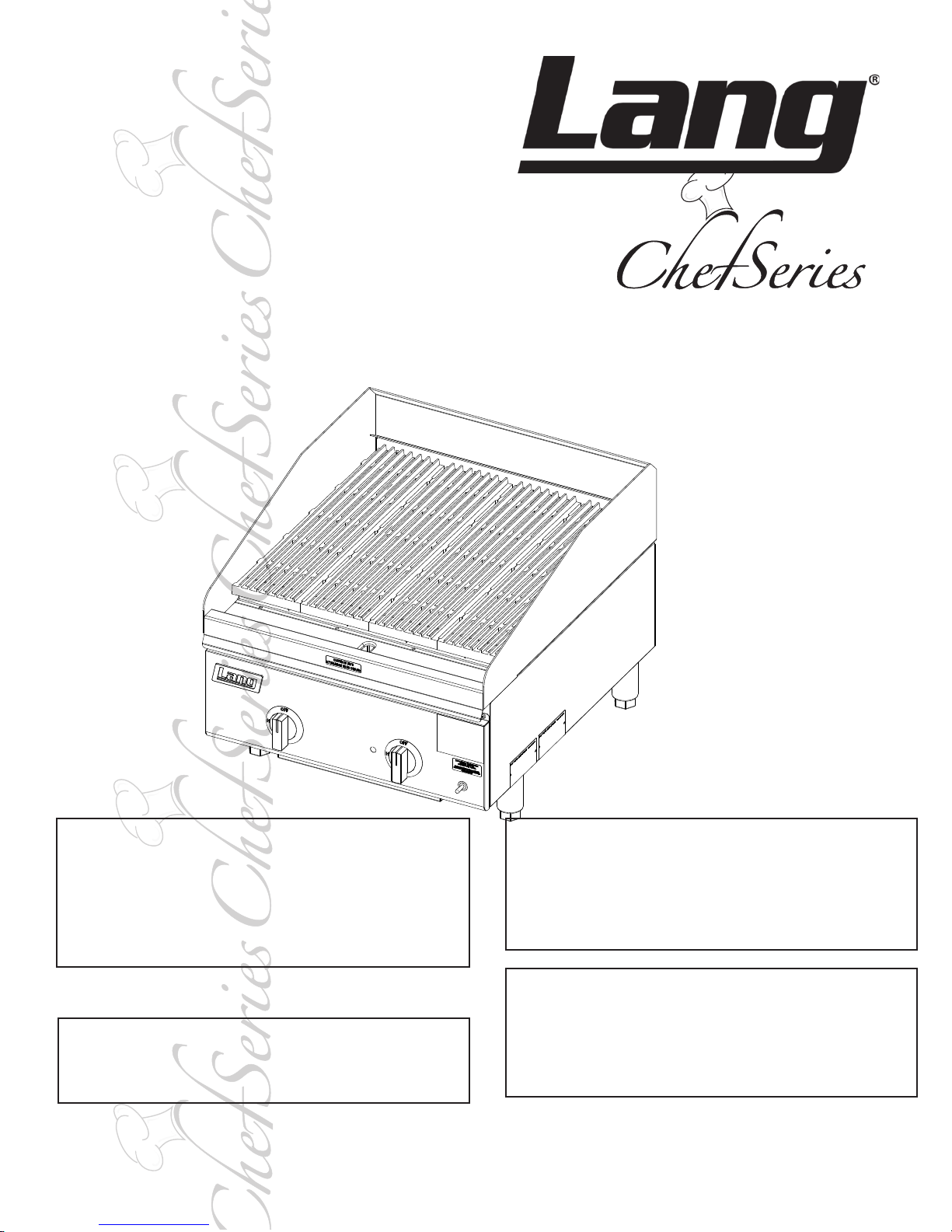
Lang 2124ZRCB User manual
1
IL1883a
WARNING: Improperinstallation,adjustment,
alteration, service or maintenance can cause
property damage, injury or death. Read
the installation, operating and maintenance
instructions thoroughly before installing or
servicing this equipment.
FOR YOUR SAFETY: Do not store or use
gasoline or other ammable vapors or liquids
in the vicinity of this or any other appliance.
WARNING: This appliance shall be installed
in accordance with current regulations and
used only in well-ventilated space. Refer to
instructions before installing and using this
appliance.
In addition, there should be posted, in a
prominent location, detailed instructions to
be followed in the event the operator smells
gas. Obtain the instructions from the local
gas supplier.
GAS
CHARBROILER
2124, 2136, 2148, 2160, 2172 (ZRCB)
Installation and
Operation
Instructions
2M-W1649 Rev. A 4/07/11
Retain This Manual for Future Reference.
22
SAFETY SYMBOL
Model No.:
Serial No.:
Voltage:
1-Phase or 3 Phase:
Purchased From:
Location:
Purchase Date:
Installed Date:
These symbols are intended to alert the user to the presence of important operating
and maintenance instructions in the manual accompanying the appliance.
FOR YOUR SAFTEY
DO NOT STORE OR USE GASOLINE OR OTHER FLAMMABLE VAPORS AND LIQUIDS IN
THE VICINTIY OF THIS OR ANY OTHER APPLIANCE.
The installation of the Appliance must conform to the NATIONAL FUEL GAS CODE "ANSI Z223.1 - LATEST
EDITION" AND ALL LOCAL GAS COMPANY RULES AND REGULATIONS.
IN CANADA INSTALLATION SHALL BE IN ACCORDANCE WITH THE CURRENT CAN/CGA-B149.1 NATURAL
GASINSTALLATIONCODEORCAN/CGA-B149.2PROPANEINSTALLATIONCODEANDLOCALCODESWHERE
APPLICABLE. POST IN PROMINENT LOCATION
INSTRUCTIONS TO BE FOLLOWED IN THE EVENT USER SMELLS GAS. THIS INFORMATION
SHALL BE OBTAINED BY CONSULTING YOUR LOCAL GAS SUPPLIER. AS A MINIMUM, TURN
OFF THE GAS AND CALL YOUR GAS COMPANY AND YOUR AUTHORIZED SERVICE AGENT.
EVACUATE ALL PERSONNEL FROM THE AREA.
WARNING
IMPROPER INSTALLATION, ADJUSTMENT, ALTERATION, SERVICE OR MAINTENANCE CAN
CAUSE PROPERTY DAMAGE, INJURY OR DEATH. READ THE INSTALLATION, OPERATION
& MAINTENANCE INSTRUCTIONS THOROUGHLY BEFORE INSTALLING OR SERVICING THIS
EQUIPMENT.
WARNING
RISK OF FIRE OR ELECTRIC SHOCK
DO NOT OPEN
WARNING, TO REDUCE THE RISK OF ELECTRICAL SHOCK, DO NOT REMOVE
CONTROL PANEL. NO USER-SERVICABLE PARTS INSIDE.
REPAIRS SHOULD BE DONE BY AUTHORIZED SERVICE PERSONNEL ONLY.
NOTICE
Using any part other than genuine Lang factory supplied parts relieves the manufacturer of all liability.
Lang reserves the right to change speci cations and product design without notice. Such
revisions do not entitle the buyer to corresponding changes, improvements, additions or
replacements for previously purchased equipment.
Due to periodic changes in designs, methods, procedures, policies and regulations, the
specifications contained in this sheet are subject to change without notice. While Lang
Manufacturing exercises good faith efforts to provide information that is accurate, we are
not responsible for errors or omissions in information provided or conclusions reached as a
result of using the speci cations. By using the information provided, the user assumes all risks in con-
nection with such use.
MAINTENANCE AND REPAIRS
Contact your local dealer for service or required maintenance. Please record the model number, serial
number, voltage and purchase & Installation Information in the area below and have it ready when you
call to ensure a faster service.

3
TABLE OF CONTENTS
Specications 4
Equipment Description 5
General Installation Data
Exhaust Canopy 6
Air Supply 6
Leveling Unit 7
Placing Radiants - RCB Series 8
Gas Piping 8
Manual Shut-Off Valve 8
Connecting Gas Supply Line 8
Propane Gas Conversion 8
Checking for Gas Leaks 8
Pilot Lighting Instructions 9
Burner Ignition & Adjustment 9
General Operating Instructions
Water Pan 10
Burner Operation 10
Lighting 10
Broiling 10
Tilting the Grate 10
Shutting Down Instructions 10
Cleaning 10
Exploded View & Parts List 11 - 17
PROBLEMS, QUESTIONS or CONCERNS
Before you proceed consult you authorized Lang service agent directory
or
Call the Lang Technical Service & Parts Department at 314-678-6315.
NOTICE Service on this or any other Lang appliance must be performed by
qualied personnel only.
Consult your Lang Authorized Service Agent Directory.
You can call our toll free number 314-678-6315 or
visit our website www.langworld.com for the service agent nearest you.

4
SPECIFICATIONS
36"
(913)
4"
(102)
16 5/8"
(422)
3"
(77)
3 3/16"
(81)
23"
(584)
4"
(102)
ELECTRICAL
CONNECTION
5 1/2 FT CORD
Front View/ElevationTop View/Plan
IL1826a
EQUIPMENT SPECIFICATIONS
GAS CHEFSERIES CHARBROILER
Model Height x Width x Depth Clearance from Weight Fright Class
(Not Including legs) combustible surface* Actual Shipping
2124ZRCB 10-58” X 24” X 28-5/8”
Sides & Back: 4”
165 lbs. 200 lbs. 65
422mm x 610mm x 727mm 75 kg 91 kg
2136ZRCB 10-5/8” x 36” x 28-5/8” 225 lbs. 265 lbs. 65
422mm x 914mm x 727mm 102 kg 120 kg
2148ZRCB 10-5/8” x 48” x 28-5/8” 300 lbs 285 lbs 65
422mm x 1219mm x 727mm 136 kg 130 kg
2160ZRCB 10-5/8” x 60” x 28-5/8” 385 lbs. 430 lbs. 65
422mm x 1524mm x 727mm 175 kg 195 kg
2172ZRCB 10-5/8” x 72” x 28-5/8” 470 lbs 520 lbs 65
422mm x 1829mm x 727mm 214 kg 236 kg
* Noncombustible oor only
Model Gas Requirement (3/4” NPT)
2124ZRCB 64,000 BTU/hr
2136ZRCB 96,000 BTU/hr
2148ZRCB 128,000 BTU/hr
2160ZRCB 160,000 BTU/hr
2172ZRCB 192,000 BTU/hr
5
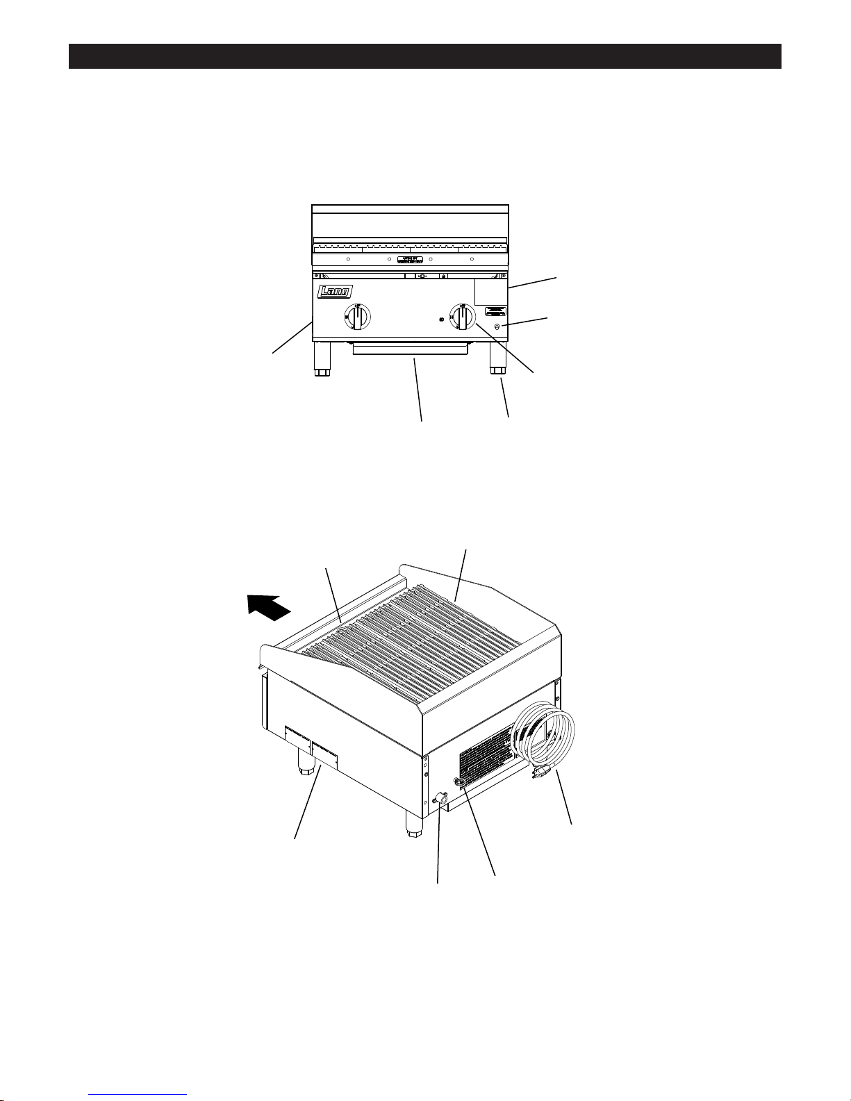
EQUIPMENT DESCRIPTION
Hinged
Front Panel
Grease Pan
Nameplate
12” Section Knob
Lighting
Instructions
On/Off Switch
4” Adj. Legs Standard
(Legs & Casters Optional)
Gas Inlet Wall
Mounting
Power Cord
Grease Trough Grates
Front
IL1884

6
GENERAL INSTALLATION DATA
This equipment is designed and sold for commercial use only by personnel trained and
experienced in its operation and is not sold for consumer use in and around the home nor
for use directly by the general public in food service locations.
The Lang series gas charbroiler is equipped for the type of gas indicated on the nameplate
mounted on the front panel. All units are shipped from the factory for use with natural gas.
The unit can easily be converted for use with propane gas: see propane gas.
-IMPORTANT-
Be sure to remove all paper protection and packing material from unit prior to
lighting.
INSTALL IN NON-COMBUSTIBLE LOCATIONS ONLY! Clearance from non-
combustibleconstructionmustbe4"minimumfrombackandsides. Forservicing,
6" is recommended from back of unit.
TheinstallationoftheAppliancemustconformtotheNATIONALFUELGAS
CODE "ANSI Z223.1 - LATEST EDITION"ANDALL LOCALGAS COMPANY
RULES AND REGULATIONS.
IN CANADA INSTALLATION SHALL BE IN ACCORDANCE WITH THE
CURRENT CAN/CGA-B149.1 NATURAL GAS INSTALLATION CODE OR
CAN/CGA-B149.2 PROPANE INSTALLATION CODE AND LOCAL CODES
WHERE APPLICABLE. NOTICE
When this appliance is installed with casters, it must be installed with the casters supplied, a
connector complying with either ANSI Z21.69 or CAN/CGA-6.16 and a quick-disconnect device
complying with either ANSI Z21.41 or CAN1-6.9. It must also be installed with restraining
means to guard against transmission of strain to the connector, as specied in the appliance
manufacturer's instructions.
For your protection, we recommend a qualied installing agency install this appliance.
They should be familiar with gas installations and your local gas requirements. In any
case, your gas company should be called to approve the nal installation.
This appliance, its pressure regulator and its individual shutoff valve must be disconnected
from the gas supply piping system during any pressure testing of that system at test
pressures in excess of 1/2 PSIG. This appliance and its pressure regulator must be isolated
from the gas supply piping system by closing its individual manual shutoff valve during any
pressure testing of the gas supply piping system at test pressures equal to or less than 1/2
PSIG.
EXHAUST CANOPY
Open hearth broilers inherently create a good deal of heat and smoke and should be
installed under an efcient exhaust hood with ame proof lters. A vertical distance of not
less than 48" shall be provided between the top of the appliance and lters or any other
combustible material. Exhaust installation must conform to local codes.
AIR SUPPLY
Provisions for adequate air supply must be provided.
Air for combustion enters from the bottom of the unit.
Do not obstruct this area.
CAUTION
CAUTION
7
IL1887a
GENERAL INSTALLATION DATA (continued)
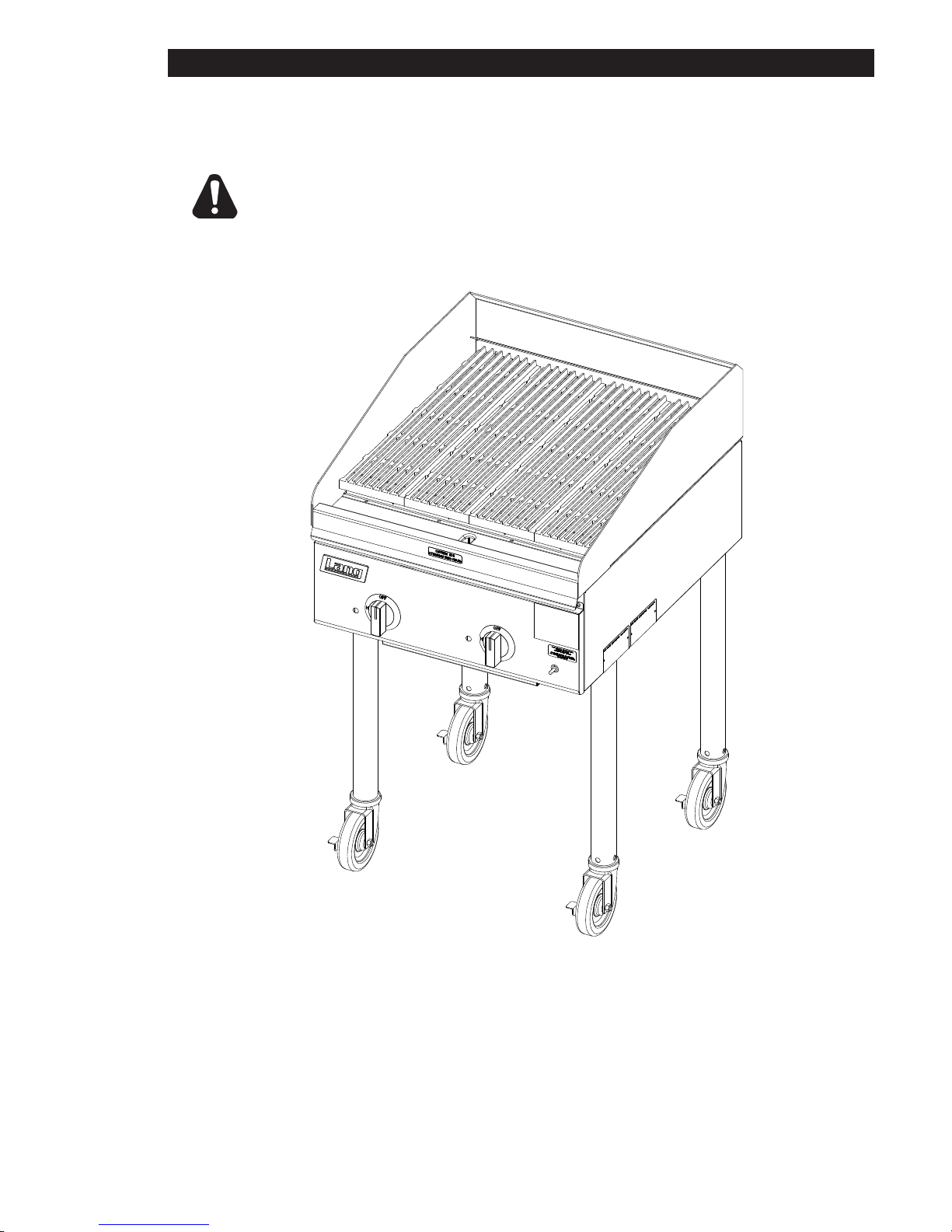
LEVELING UNIT
This charbroiler is supplied with 4 feet or oor stand legs which must be screwed into the
body. Unit must be level. Level unit by adjusting the (4) feet which have an adjustment of
1-3/4" for accurate and perfect line-up with other units.
DO NOT INSTALL WITHOUT ATTACHING FEET OR SUPPLIED
STAND LEGS AND SHELF - DO NOT REMOVE FEET.
CAUTION
Model 2124ZRCB with tall legs.
Tall legs and casters are optional.

8
FLOW
BACK OF UNIT
IL1828a
DRIP LEG*
GAS
SHUT-OFF
VALVE*
SUPPLIED
REGULATOR
* by others
GAS
SUPPLY*
VENT
GENERAL INSTALLATION DATA (continued)
PLACING RADIANTS
After the unit is unpacked and installed, place 1 radiant above each burner. Install each
radiant on 2 slots of the rear wall and on the 2 pins of the front wall of the liner weld
assembly. Refer to the exploded view in this manual for orientation of the radiants.
GAS PIPING
Gas piping shall be of such size and so installed as to provide a supply of gas sufcient
to meet the full gas input of the appliance. If the appliance is to be connected to existing
piping, it shall be checked to determine if it has adequate capacity. Joint compound shall
be used sparingly and only on the male threads of the pipe joints. Such compounds shall
be resistant to the action of L.P. gases. WARNING: Any loose dirt or metal particles which
are allowed to enter the gas lines on this appliance will damage the valve and affect its
operation. When installing this appliance, all pipe and ttings must be free from all internal
loose dirt..
MANUAL SHUT OFF VALVE
A manual shut off valve should be
installed upstream from the manifold
and within six feet of the charbroiler.
CONNECTING GAS SUPPLY LINE
The gas inlet of the charbroiler is
sealed at the factory to prevent entry
of dirt. Do not remove this seal until
the actual connection is made to the
gas supply line.
PROPANE GAS - CONVERSION
This charbroiler is equipped with xed
orice hoods and is shipped from the
factory for use with natural gas. To
convert to propane gas, install the burner orice hoods, located in the water pan, as follows:
Remove grates, radiants and burners.
Remove the burner orice hoods and install the orice hoods supplied.
Replace the burners, radiants, and grates.
Set manifold pressure to (10) inch water column. A 1/8" pipe plug on the burner manifold can
be removed for attaching a pressure gauge. Remove the slotted, or hex-threaded plug from
the pressure regulator. Invert the plug and re-install. The letters "LP" should now be visible
on the plug. The regulator is now set for 10" (25.4 cm) water column. Attach the conversion
label, supplied with the unit, close to the nameplate.
CHECKING FOR GAS LEAKS
Check entire piping system for leaks. Soap and water solution or other material acceptable
for the purpose, shall be used in locating gas leakage.
Matches, candle ame or other sources of ignition shall not be used for
locating gas leaks.
1.
2.
3.
4.
CAUTION

9
GENERAL INSTALLATION DATA (continued)
PILOT LIGHTING INSTRUCTIONS
The charbroiler is equipped with an automatic pilot/ignter with an electronic spark.
Be sure all gas control knobs on the units front panel are turned OFF.
Turn on main gas supply valve to unit.
Turn "ON" the switch on front control panel to activate electonic pilot lighter.
The pilot igniter tubes on this broiler have been pre-set at the factory. Turn the adjustable screw
counterclockwise to open and clockwise to close.
Adjust pilot light ames, if necessary as small as possible, usually about 3/8" high, but high
enough to light burner immediately when burner valve is turned on high.
Turn burner knobs to desired setting.
To turn burners off, turn knobs off and turn off switch on front control panel.
BURNER IGNITION AND ADJUSTMENT
To ignite burners turn burner valve knob counter clockwise to "ON"position.
Slowly decrease openings of air shutters to give a soft blue ame having luminous tips, then
slowly increase openings to a point where the yellow tips disappear and a hard blue ame is
obtained.
DO NOT ATTEMPT TO OPERATE UNIT DURING A POWER FAILURE.
1.
2.
3.
4.
5.
6.
7.
1.
2.
10
GENERAL OPERATING INSTRUCTIONS
WATER PAN
The water pan is located at the
bottom of the unit, and is easily
removed from the front of the unit.
Water should be added to the
water pan to just cover bottom and
replaced as necessary. The water
pan helps prevent are ups and
catches grease.
BURNER OPERATION
Each burner is controlled by an
individual high-low, on-off valve. A
variety of broiling temperatures may
be obtained by turning the burner
valve knob to any position between ON and LO. It is possible through this arrangement to
have a high heat or searing section, while having a low heat nishing or holding section. For
the searing operation, turn the valve counter clockwise for the section to a position of "ON"
or close to it. For holding or nishing, turn the valves closer to the "LO" position on the dial.
You select the heat pattern you like, and set the valves accordingly. Be sure burners are
staying fully lit when set in low positions.
LIGHTING
When broiler is rst lit, it will smoke for approximately 20-30 minutes until the preservation
OILS and impurities are burned off.
BROILING
Turn valves on and pre-heat unit on "ON" before attempting to broil. You will have to
experiment with the grate settings and the valve settings for your particular food products.
Check water pans frequently and add a sufcient amount of water when necessary.
Hot water vapors rising from the water pans and through the combustion chamber helps
reduce are ups. Exercise care when using your broiler.
TILTING THE GRATE
Raise or lower the grate to the next step by lifting the grate at the back of the charbroiler
where the grate rests. Use potholders or gloves to reposition.
CHARBROILERS ARE HOT! NEVER ATTEMPT TO CHANGE THE GRATE
POSITION WHILE FOOD PRODUCTS ARE COOKING. FLARE UPS CAN
OCCUR UNEXPECTEDLY. TURN OFF CHARBROILER, AND ALLOW THE
CHARBROILER TO COOL.
SHUTTING DOWN INSTRUCTIONS
Turn "OFF" the pilot lighting switch on the front panel and put the burner valve knobs to the
off position to turn burners off and close manual valve gas shutoff.
CLEANING
Clean regularly. Remove grate section to sink for washing. Brush out carboned particles.
Remove and wash water pan. Wipe exterior surfaces with detergent and a cloth.
A non-abrasive cleaner can be used on caked areas.
CAUTION
Keep Water Pan
filled with water to
Prevent Flare-ups
IL2223
This manual suits for next models
8
Table of contents
Other Lang Grill manuals


Popular Grill manuals by other brands


Kenmore
Kenmore 415.16123800 Use and care guide

Camp Chef
Camp Chef PG24CLAU Warning & instruction booklet

Tucker Barbecues
Tucker Barbecues GTR Series Assembly, installation and operating instructions

Monogram
Monogram ZGG540NCP1SS owner's manual

Equipex
Equipex Sodir Savoy Operation manual

Gaggenau
Gaggenau VR 414 610 use and care manual


