manuals.online logo
Brands
  1. Home
  2. •
  3. Brands
  4. •
  5. Larson Electronics
  6. •
  7. Security Camera
  8. •
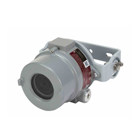
  9. Larson Electronics EXPCMR-NDAA-IP-POE Series User manual

Larson Electronics EXPCMR-NDAA-IP-POE Series User manual

IP Camera Network Setup Guide
Larson Electronics, LLC Phone: (877) 348-9680 Fax: (903) 498-3364 www.larsonelectronics.com 1 of 11
USER MANUAL
AND
QUICK START GUIDE
Network IP Cameras
EXPCMR-NDAA-IP-POE SERIES
Larson Electronics, LLC Phone: (877) 348-9680 Fax: (903) 498-3364 www.larsonelectronics.com 2 of 11
This device meets the CAN ICES-3 (A)/NMB-3(A) standards requirements.
Safety Instruction
These instructions are intended to ensure that the user can use the product correctly to
avoid danger or property loss.
The precaution measure is divided into ‘Warnings’and ‘Cautions’:
Warnings: Serious injury or death may be caused if any of these warnings are
neglected.
Cautions: Injury or equipment damage may be caused if any of these cautions are
neglected.
Warnings Follow these safeguards to
prevent serious injury or death. Cautions Follow these precautions to
prevent potential injury or material
damage.
Warnings:
This installation should be made by a qualified service person and should conform
to all the local codes.
Pleaseinstallblackouts equipment into the power supply circuit for convenient
supply interruption.
If the product does not work properly, please contact your dealer or the nearest
service center. Never attempt to disassemble the camera yourself. (We shall not
assume any responsibility for problems caused by unauthorized repairor
maintenance.)
Make sure the supply voltage is within the voltage rating.
Ensure that the marked T rating is less than the ignition temperature of the
hazardous atmosphere.
DO NOT operate in ambient temperatures above those indicated on the product
nameplate.
DO NOT operate if the lens, cord, seals, housing, receptacles, etc. are cracked or
damaged. If so, discontinue use and contact manufacturer for replacement parts.
All fasteners should be properly seated.
IP Camera Network Setup Guide
TO AVOID EXPLOSION:
Larson Electronics, LLC Phone: (877) 348-9680 Fax: (903) 498-3364 www.larsonelectronics.com 3 of 11
Cautions:
Make sure the power supply voltage is correct before using the camera.
Do not drop the camera or subject it to physical shock.
Do not touch sensor modules with fingers. If cleaning is necessary, use a clean
cloth with a bit of ethanol and wipe it gently. If the camera will not be used for an
extended period of time, put on the lens cap to protect the sensor from dirt.
Do not aim the camera lens at the strong light such as sun or incandescent lamp.
The strong light can cause fatal damage to the camera.
The sensor may be burned out by a laser beam, so when any laser equipment is
being used, make sure that the surface of the sensor not be exposed to the laser
beam.
Do not place the camera in extremely hot, cold temperatures (the operating
temperature should be between -30°C ~ 60°C), and do not expose it to high
electromagnetic radiation.
To avoid heat accumulation, good ventilation is required for a proper operating
environment.
Keep the camera away from water and any liquid during installation.
While shipping, the camera should be packed in its original packing.
Notes:
For the camera supports IR, you are required to pay attention to the following
precautions to prevent IR reflection:
Dust or grease on the dome cover will cause IR reflection. Please do not remove
the dome cover film until the installation is finished. If there is dust or grease on
the dome cover, clean the dome cover with clean soft cloth and isopropyl alcohol.
Make certain the installation location does not have reflective surfaces of objects
too close to the camera. The IR light from the camera may reflect back into the
lens causing reflection.
The foam ring around the lens must be seated flush against the inner surface of
the bubble to isolate the lens from the IR LEDS. Fasten the dome cover to camera
body so that the foam ring and the dome cover are attached seamlessly.
IP Camera Network Setup Guide
Larson Electronics, LLC Phone: (877) 348-9680 Fax: (903) 498-3364 www.larsonelectronics.com 4 of 11
•H.265+ / H.265 / H.264OVC / H.264 / MJPEG
compression
•120 dB Wide Dynamic Range
•Ultra low light sensor
•120 ft Full Frame Illumination Smart IR array,
•Supports onboard storage up to 128GB Max
microSD (card not included)
•IP67 rated, −22 °F ~ 140 °F temperature range
•ONVIF Profile S & Profile G, PSIA, CGI, ISAPI
WARNING
!
Failure of the power or Ethnernet connector due to
moisture or another contaiminant is considered an
installation error, which voids the waranty. If installing
this camera in a location such as an overhang, shop,
garage, kitchen, etc. where high humidity or dust is
present, seal these connections adequately.
CAUTION
Do not apply power to the camera at this time. Before
applying power to the camera, ensure that the polarity is
correct. An incorrect connection may cause a malfunction
and can damage the camera.
6. Secure the camera to the mounting surface using appropriate
screws.
7. Apply power to the camera through the 12Vdc power cable or
PoE switch/injector, as configured.
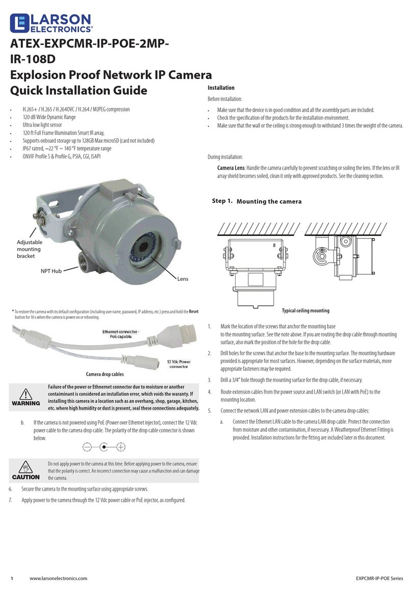
Camera drop cables
Installation
Before installation:
•Make sure that the device is in good condition and all
the assembly parts are included.
•Check the specification of the products for the
installation environment.
•Make sure that the wall or ceiling is strong enough to
withstand 3 times the weight of the camera.
During installation:
•Camera Lens: Handle the camera carefully to prevent
scratching or soiling the lens. If the lens or IR array
shield becomes soiled, clean it only with approved
products. See the cleaning section.
Step 1. Mounting the camera
Typical ceiling mounting
1. Mark the location of the screws that anchor the mounting base
to the mounting surface. See the note above. If you are
routing the drop cable through mounting surface, also mark
the position of the hole for the drop cable.
2. Drill holes for the screws that anchor the base to the mounting
surface. The mounting hardware provided is appropriate for
most surfaces. However, depending on the surface materials,
more appropriate fasteners may be required.
3. Drill a 3/4” hole through the mounting surface for the drop
cable, if necessary.
4. Route extension cables from the power source and LAN
switch (or LAN with PoE) to the mounting location.
5. Connect the network LAN and power extension cables to the
camera drop cables:
a. Connect the Ethernet LAN cable to the camera LAN drop
cable. Protect the connection from moisture and other
contamination, if necessary. A Weatherproof Ethernet
Fitting is provided. Installation instructions for the fitting
are included later in this document.
b. If the camera is not powered using PoE (Switch or
Injector), connect the 12 Vdc power cable to the camera
drop cable. The polarity of the drop cable is shown to the
left.
Lens
NPT Hub
Adjustable
mounting
bracket
Larson Electronics, LLC Phone: (877) 348-9680 Fax: (903) 498-3364 www.larsonelectronics.com 5 of 11
IP Camera Network Setup Guide
THIS PAGE INTENTIONALLY
LEFT BLANK
Larson Electronics, LLC Phone: (877) 348-9680 Fax: (903) 498-3364 www.larsonelectronics.com 6 of 11
1. Download the Vigilant Toolbox from the web: https://www.alibisecurity.com/media/docs/AlibiVigilantToolbox-
B1122-1-0-1-200828.zip
2. Un-zip the file on a computer with Microsoft Windows that is connected to the LAN where your camera is
connected.
3. Run the setup file contained in the zip file. Follow the on-screen instructions to install the file.
NOTE : Be sure to allow the software administrative access or it will not work properly.
4. Open the Vigilant Toolbox application. When the application opens, it automatically “discovers” and lists all
compatible devices on the LAN. The discovery of devices can take several minutes. Take note of the IP
address of your camera as you will need this to log into and activate it. See below.
Step 2. “Activate” Inactive Camera
NOTE: Cameras are shipped with the default IP Address of 172.16.0.xxx. The last set of numbers in your IP
address will be random, but will always be in the 172.16.0.xxx subnet. See "Step 3. Modify Network
Parameters" for more information on how to change these.
DEFAULTS: Username: admin Password: 123456
When a camera is first installed, or reset to its factory configuration, it must be “Activated” before it can be used. A
device is “Activated” when a password is assigned to the admin username of the device. To do this you will need to
login to the camera through a browser.
In the following steps, a camera is activated and configured for its network using Microsoft Edge.
IP Camera Network Setup Guide
This guide provides generic instructions for activating and setting up the network parameters for new NDAA cameras
Connected to anetwork switch with PoE using the Vigilant Toolbox.The examples shown herein activate an NDAA
camera and configure its network settings.
About the Vigilant Toolbox
The Vigilant Toolbox is a PC-based network utility for discovery of compatible devices on an IP network. It provides an
easy way to configure cameras, record network configuration settings, and set device passwords. It can be installed on a
Microsoft Windows operating system that has access to the IP network where your devices are installed.
Step 1. Install the Software
Larson Electronics, LLC Phone: (877) 348-9680 Fax: (903) 498-3364 www.larsonelectronics.com 7 of 11
1. Scan through the list of devices the Vigilant Toolbox discovered for the device you want to activate (see
below) and take down the IP address of the device.
2. To login to your device and create a new password you will need to change the IPv4 settings of your PC to
match those of the camera.
a. Click on the Windows start menu or press the Windows key on your keyboard and type "View network
connections" and press enter to bring up your Network Connections (Fig. A). Click once on your current
network connection to highlight it and then choose "Change settings of this connection". (Fig. A)
b. In the properties menu, highlight "Internet Protocol Version 4 (TCP/IPv4)" and the click the properties
button. (Fig. B)
c. In the Internet Protocol Version 4 (TCP/IPv4) properties, if "Obtain an IP address automatically" is
checked, click the circle next to "Use the following IP address". NOTE: If you are currently using a
static IP address, be sure to note this information down so you can switch it back later. (Fig. C)
d. In the IP address box you will need to input an IP address of 172.16.0.xxx. For the last section in the IP
address, it can be any number between 2 and 250, as long as it is not the same as the one you noted
down earlier for your device. In the Subnet Mask box use 255.255.255.0. All other boxes can be left
blank. (Fig. C)
e. Click OK to close that dialogue box, and then click close, to close the previous dialogue box.
CAUTION: If you lose your admin (administrator) password, you cannot configure the device or restore it to its factory
settings. To reset you password, call your support organization for specific instructions.
IP Camera Network Setup Guide
FIG. A
FIG. B
IP Camera Network Setup Guide
FIG. C
3. Open Microsoft Edge and input the IP address of your camera into the search bar and press enter.
a. Navigate to the top right of the browser window and select the 3 horizontal dots and then look down the
popup list and click "Reload in Internet Explorer mode"(Fig. D)
b. After the page reloads in Internet Explorer mode you will be able to download and install the plugin so
that you can view the camera. (Fig. E)
c. Click "Run" in the popup along the bottom of the window and after following any prompts click "Allow".
(Fig. F)
d. Input the default Username and Password into the appropriate boxes and then click OK. You will get
another popup window instructing you to create a new password for your device. The new password
must be at least 9 characters in length, contain at least 1 number, 1 lowercase letter, 1 uppercase
letter and 1 symbol. Click OK after you enter your new password (Fig. G) and another window will
popup stating that you need to log in with your new password, click OK and wait until the page
refreshes. (Fig. H)
e. After creating your new password and the page refreshes, the device is now activated.
Larson Electronics, LLC Phone: (877) 348-9680 Fax: (903) 498-3364 www.larsonelectronics.com 8 of 11
IP Camera Network Setup Guide
Larson Electronics, LLC Phone: (877) 348-9680 Fax: (903) 498-3364 www.larsonelectronics.com 9 of 11
FIG. D FIG. E
FIG. F
FIG. G
FIG. H
Larson Electronics, LLC Phone: (877) 348-9680 Fax: (903) 498-3364 www.larsonelectronics.com 10 of 11
1. Once you have logged into the device with your new password you will see the live view. Click on Setup to
change the parameters of the device. (See below)
2. In the Setup screen you will have many different options listed on the left side. Click on the Network tab, or click
Network in the Common tab that is already expanded. (Fig. I)
a. Enable DHCP: You can select DHCP to acquire compatible network settings from a DHCP server
installed on the LAN. However, these settings can be changed by the DHCP server. Since it is
recommended to use a static IP address, you can use DHCP to acquire compatible network settings, and
then select Static and save that configuration to retain the new network parameters. (Fig. J)
b. Static: If you were using a static IP address in Step 2, Section 2, part C, then you can input an unused
static IP address here for your new device (not the same as the one used for your PC or other devices on
your network, consult with your network administrator if you are unsure what IP addresses are available).
c. After inputting the new IP address for your device, click the Save button. (NOTE: After saving your
settings you will need to return the IPv4 settings of your PC back to the original settings. To do
this simply follow Step 2, Section 2 as done previously)
NOTE: If you have set your camera to DHCP, you can run the Vigilant Toolbox again after
returning your PC IPv4 settings to the previous settings, to get the new IP address of your camera.
d. To login to your camera again, input the new IP address into the search bar and press enter. Use
"admin" as the Username and your newly created password that you set in the previous step.
Step 3. Modify Network Parameters
IP Camera Network Setup Guide
NOTE:Most IP cameras have a Reset button for returning the camera configuration to its factory settings. The reset
button needs to be pressed with the camera disconnected from power. Continue holding the reset button down and plug
the camera back into power and continue to hold the reset button for an additional 30 - 45 seconds.
NOTE: For more details on using the functions of this camera, refer to the instruction manual for the Camera Management
Software (CMS) you are using.
THESE INSTRUCTIONS MAY NOT COVER ALL DETAILS OR VARIATIONS OF THIS PRODUCT FOR YOUR EQUIPMENT OR INSTALLATION REQUIREMENTS. SHOULD FURTHER
INFORMATION NOT COVERED BY THESE INSTRUCTIONS BE REQUIRED, PLEASE CONTACT LARSON ELECTRONICS BY EMAIL AT [email protected] OR BY PHONE AT
1-877-348-9680 FOR FURTHER ASSISTANCE.
PLEASE VISIT LARSONELECTRONICS.COM FOR WARRANTY AND RETURN INFORMATION.
Larson Electronics, LLC Phone: (877) 348-9680 Fax: (903) 498-3364 www.larsonelectronics.com 11 of 11
IP Camera Network Setup Guide
FIG. I
FIG. J

This manual suits for next models

1

Other Larson Electronics Security Camera manuals
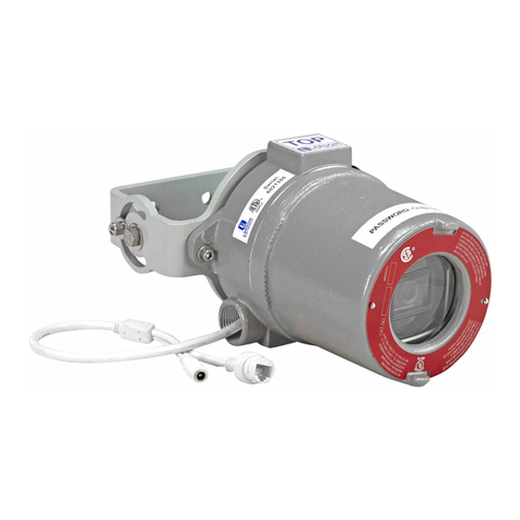
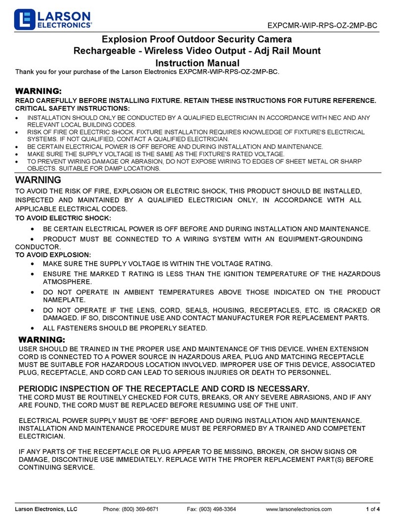
Larson Electronics EXPCMR-WIP-RPS-OZ-2MP-BC User manual

Larson Electronics

Larson Electronics EXPCMR-WIP-RPS-OZ-2MP-BC User manual

Larson Electronics EXPCMR-ALG-1080P-IC-M-16.7-25-L21.20-1227 User manual

Larson Electronics

Larson Electronics EXPCMR-ALG-1080P-IC-M-16.7-25-L21.20-1227 User manual

Larson Electronics HAL-CRM-CRNM-ALG-1080P-12V User manual

Larson Electronics

Larson Electronics HAL-CRM-CRNM-ALG-1080P-12V User manual

Larson Electronics EXPCMR-ALG-HDSD-1080P-12VDC User manual

Larson Electronics

Larson Electronics EXPCMR-ALG-HDSD-1080P-12VDC User manual

Larson Electronics EXPCMR-CER-IP-POE-4MP-IR-V3 User manual

Larson Electronics

Larson Electronics EXPCMR-CER-IP-POE-4MP-IR-V3 User manual

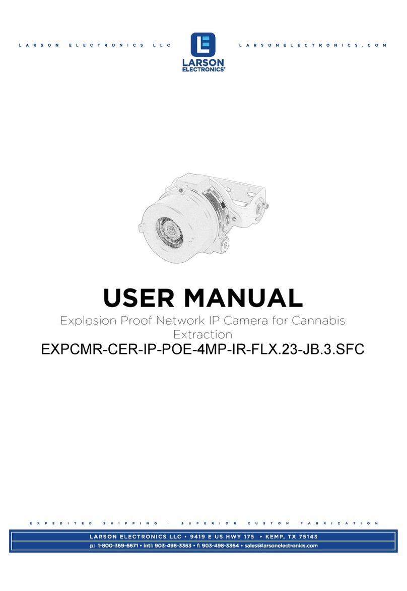
Larson Electronics EXPCMR-CER-IP-POE-4MP-IR-FLX.23-JB.3.SFC User manual

Larson Electronics

Larson Electronics EXPCMR-CER-IP-POE-4MP-IR-FLX.23-JB.3.SFC User manual

Larson Electronics IDCMR-SL-IP-POE-4MP User manual

Larson Electronics

Larson Electronics IDCMR-SL-IP-POE-4MP User manual

Larson Electronics EXPCMR-ALG-1080P-IC-16.7-25-L21.20-1227 User manual

Larson Electronics

Larson Electronics EXPCMR-ALG-1080P-IC-16.7-25-L21.20-1227 User manual

Larson Electronics EXPCMR-ALG-1080P-24V User manual

Larson Electronics

Larson Electronics EXPCMR-ALG-1080P-24V User manual

Larson Electronics EXPCMR-IP-POE-4MP-IR-FLX.23-JB.3.SFC User manual

Larson Electronics

Larson Electronics EXPCMR-IP-POE-4MP-IR-FLX.23-JB.3.SFC User manual

Larson Electronics IDCMR-IP-POE-DMIP User manual

Larson Electronics

Larson Electronics IDCMR-IP-POE-DMIP User manual

Larson Electronics EXPCMR-IP-POE-DPTZ User manual

Larson Electronics

Larson Electronics EXPCMR-IP-POE-DPTZ User manual

Larson Electronics ATEX-EXPCMR-IP-POE-2MPIR-108D User manual

Larson Electronics

Larson Electronics ATEX-EXPCMR-IP-POE-2MPIR-108D User manual

Larson Electronics IDCMR-SRMT-IP-POE-4MP User manual

Larson Electronics

Larson Electronics IDCMR-SRMT-IP-POE-4MP User manual

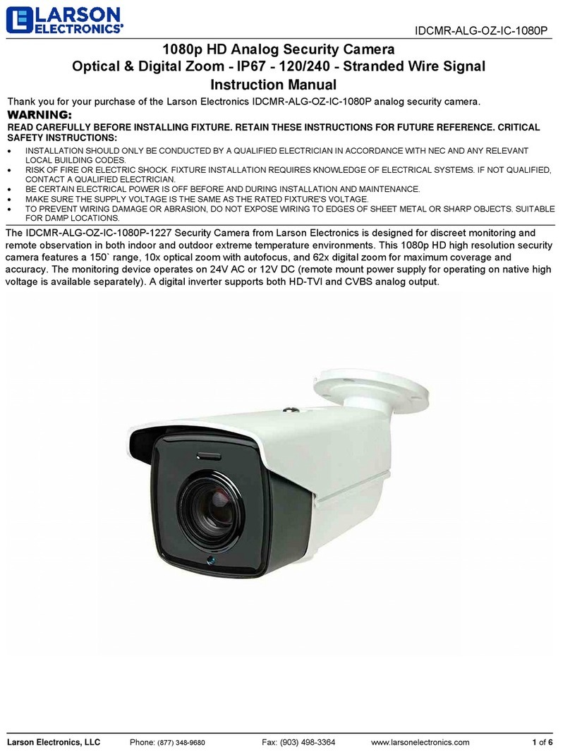
Larson Electronics IDCMR-ALG-OZ-IC-1080P User manual

Larson Electronics

Larson Electronics IDCMR-ALG-OZ-IC-1080P User manual

Larson Electronics EXPCMR-ALG-1080P-1227 User manual

Larson Electronics

Larson Electronics EXPCMR-ALG-1080P-1227 User manual

Larson Electronics IDCMR-IP-POE-4MP User manual

Larson Electronics

Larson Electronics IDCMR-IP-POE-4MP User manual

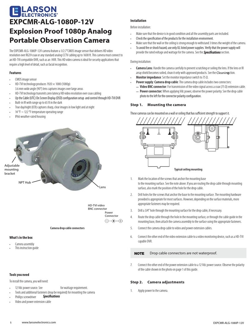
Larson Electronics EXPCMR-ALG-1080P-12V User manual

Larson Electronics

Larson Electronics EXPCMR-ALG-1080P-12V User manual

Larson Electronics EXPCMR-IP-POE Series User manual
Larson Electronics

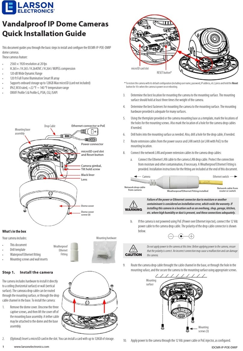
Larson Electronics EXPCMR-IP-POE Series User manual

Popular Security Camera manuals by other brands

Fortinet FortiCam CD51 Mounting guide

Fortinet

Fortinet FortiCam CD51 Mounting guide

Channel Vision 6010 Specification sheet

Channel Vision

Channel Vision 6010 Specification sheet

Idis DC-S1163F quick guide

Idis

Idis DC-S1163F quick guide

Axis AXIS P32-V Mk II Series installation guide

Axis

Axis AXIS P32-V Mk II Series installation guide

AVer FB3028-RT1 installation guide

AVer

AVer FB3028-RT1 installation guide

Grundig GCH-K0323D owner's manual

Grundig

Grundig GCH-K0323D owner's manual

Vitek Transcendent VTC-TNB5RMS quick start guide

Vitek

Vitek Transcendent VTC-TNB5RMS quick start guide

Coomatec c902 instruction manual

Coomatec

Coomatec c902 instruction manual

Velleman CAMIP6 user manual

Velleman

Velleman CAMIP6 user manual

Tellur TLL331071 user manual

Tellur

Tellur TLL331071 user manual

Wansview G6 user manual

Wansview

Wansview G6 user manual

Santec SNC-421FBIA Quick installation guide

Santec

Santec SNC-421FBIA Quick installation guide

Vitek VTC-TNB4RFS quick start guide

Vitek

Vitek VTC-TNB4RFS quick start guide

Axis P5534 datasheet

Axis

Axis P5534 datasheet

ZOSI C518 quick start guide

ZOSI

ZOSI C518 quick start guide

Velleman CAMTVI13 user manual

Velleman

Velleman CAMTVI13 user manual

Axis P3904-R installation guide

Axis

Axis P3904-R installation guide

ALIBI ALI-TS2025R Quick installation guide

ALIBI

ALIBI ALI-TS2025R Quick installation guide

manuals.online logo
manuals.online logoBrands
  • About & Mission
  • Contact us
  • Privacy Policy
  • Terms and Conditions

Copyright 2025 Manuals.Online. All Rights Reserved.