Laser Tools 5931 User manual

Coil Spring Compressor
(Internal type)
www.lasertools.co.uk
Instructions
5931
2
www.lasertools.co.uk
Introduction
To compress the suspension coil spring when the spring is fitted independently of the
suspension damper (wishbone, independent and multi-link systems) and access is possible from
the bottom of the spring. The dimensions of the tool will allow access through lower wishbone
holes as small as 30mm in diameter.
The kit includes two pairs of clamp jaws that offer coverage of coil springs from 66mm to
140mm external diameter. Also included is a torque limiting bar that allows the compressor to be
used with an air impact wrench. The torque limiting bar restricts the maximum torque applied by
an air impact wrench to 100Nm. A standard ratchet can also be used but care must be taken to
ensure that the maximum torque applied does not exceed 100Nm.
Vehicle applications include Chrysler, Citroën, Ford, Honda, Kia, Mercedes-Benz, Mitsubishi,
Peugeot, Renault, Seat, Skoda, Suzuki, Toyota, Volvo, Volkswagen, BMW 3 series (1996-2013)
Mercedes-Benz W202/W204 (1997-2013).
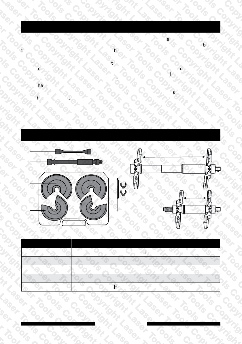
Contents
210mm
100mm
Ref Component
A Compressor: telescopic main body
B Large jaw clamp set (90mm – 140mm)
C Small jaw clamp set (66mm – 120mm)
D Torque limiting extension bar
E Fitting tool and Fork Wedges (x2)
Maximum load: 3800kgf (37,240N)
A
B
C
D
E

3
Instructions
www.lasertools.co.uk
IMPORTANT: You must refer to the manufacturer’s service instructions or documentation to
establish the correct procedures for removing the coil spring and/or damper units. The following
notes and diagrams are provided as a guide only. No liability is accepted for incorrect use of this
product.
1. Ensure the vehicle is safely and properly supported.
2. Measure the diameter of the coil spring and select either the large or small jaw clamp set as
appropriate (B or C).
3. Ensure that the coil spring is clean and free of dirt or grease where the clamps will be in
contact with it.
4. Refer to diagram Fig 1. Slide one of the jaw clamps into the top of the spring and insert the
telescopic body of the compressor (A) up inside the spring from below, with the 1/2" drive
facing downwards.
5. Connect the telescopic body of the compressor into the slot in the upper jaw clamp. Ensure
that the teeth in the compressor are locked together correctly with the clamp (See Fig 2).
6. Insert the lower jaw clamp at the lower end of the coil spring and slot it into the telescopic
body, again making sure the teeth are locating correctly.
7. Screw the handle into one of the fork wedges and insert the wedge under the upper jaw to
prevent the jaw dropping out. Unscrew the handle and use it to fit the second fork above the
lower jaw, as shown in Fig 3.
8. Apply a slight load to bring the clamp jaws together by turning the compressor drive clockwise.
Then again check that both clamp jaws are correctly located and seated securely.
9. Proceed to compress the spring to enable removal. If using an air impact gun, first fit the
torque limiting extension bar (D) onto the 1/2" drive. If using a standard ratchet, ensure that the
maximum torque applied does not exceed 100Nm. (Torque limiting extension bar can also be
used with a standard ratchet.) Use impact gun on low setting only on 1 second bursts.
10. If the spring windings touch each other then no more compression is possible. It is preferable
to stop before the windings touch.
11. Remove the torque limiting extension bar if it is being used, then remove the spring and
compressor from the vehicle.
12. Support the spring safely and drive the compressor in the opposite direction (anticlockwise,
using hand wrench only) to release the tension from the spring and allow the compressor to be
removed.
Fig. 2
Fig. 3
Fig. 1

Precautions
Precautions when using a spring compressor - PLEASE READ
• When compressed, a vehicle road spring is storing a very large amount of energy. Whilst all
possible actions have been taken to reduce the risk of slippage this risk will always be present.
• Keep hands and body clear of the spring when operating the spring compressor.
• Do not leave compressed spring unattended.
• Always wear protective head, eye and hand gear. Responsibility for damage or injury lies with the
user.
• Maintain the tool in a clean condition, especially the jaw clamps.
• Do not operate the spring compressor if parts are damaged or missing.
• Do not allow untrained persons to use the spring compressor.
WARNING: To prevent equipment damage and possible injury when fitting the
5931 to a tensioned spring always ensure the cups are positioned to allow the
force screw thread to remain engaged by a minimum of 3 full turns at the free
length of the spring.
Our products are designed to be used correctly and with care for the purpose for which they are
intended. No liability is accepted by the Tool Connection for incorrect use of any of our products, and
the Tool Connection cannot be held responsible for any damage to personnel, property or equipment
when using the tools. Incorrect use will also invalidate the warranty.
If applicable, the applications database and any instructional information provided has been designed
to offer general guidance for a particular tool’s use and while all attention is given to the accuracy
of the data no project should be attempted without referring first to the manufacturer’s technical
documentation (workshop or instruction manual) or the use of a recognised authority such as
Autodata.
It is our policy to continually improve our products and thus we reserve the right to alter
specifications and components without prior notice. It is the responsibility of the user to ensure the
suitability of the tools and information prior to their use.
If this product fails through faulty materials or workmanship, contact our
service department direct on: +44 (0) 1926 818186. Normal wear and tear
are excluded as are consumable items and abuse.
Guarantee
Distributed by The Tool Connection Ltd
Kineton Road, Southam, Warwickshire CV47 0DR
T+44 (0) 1926 815000 F+44 (0) 1926 815888
5931_Instructions_V6
Table of contents


