8
D
GB
F
E
I
Ru
09618-01.2016-DGbFEIRu
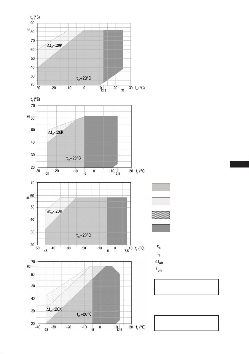
3|Areas of application
ATTENTION! Compressor operation is possible within the operating limits
shown in the diagrams. Please note the signicance
of the shaded areas. Thresholds should not be selected as design
or continuous operation points.
- Permissible ambient temperature (-20°C) - (+60°C)
- Max. permissible discharge end temperature 140 °C
- Max.permissibleswitchingfrequency8x/h.
- A minimum running time of 3 min. steady-state condition
(continuous operation) must be achieved.
For operation with additional cooling:
- Use only oils that are highly thermally stable.
- Avoid continuous operation near the limits.
For operation with capacity regulator:
- Continuousoperation,whenthecapacityregulatorisactivated,
is not permissible and can cause damage to the compressor.
- The suction gas superheat temperature may need to be reduced
or set individually when operating near to the threshold.
- When the capacity regulator is activated, the gas velocity in
the system can not under certain circumstances ensure that
sufcientoilistransportedbacktothecompressor.
Foroperationwithfrequencyconverter:
- The maximum current and power consumption must not be
exceeded. Inthecaseofoperationabovethemainsfrequency,
the application limit can therefore be limited.
When operating in the vacuum range, there is a danger of air
enteringonthesuctionside.Thiscancausechemicalreactions,
a pressure rise in the condenser and an elevated compressed-gas
temperature. Prevent the ingress of air at all costs!
Thecompressorsarelledatthefactorywiththefollowingoiltype:
- for R134a, R404A/R507, R407C FUCHS Reniso Triton SE 55
- for R22 FUCHS Reniso SP 46
Compressors with ester oil charge (FUCHS Reniso Triton SE 55) are marked with an X in the type
designation (e.g. HGX34P/380-4).
3.1 Refrigerants
• HFKW / HFC: R134a, R404A/R507, R407C
• (H)FCKW / (H)CFC: R22
3.2 Oil charge
3.3 Limits of application
INFO! Forrefilling,werecommendtheaboveoiltypes.
Alternatives: seelubricantstable,Chapter7.5.
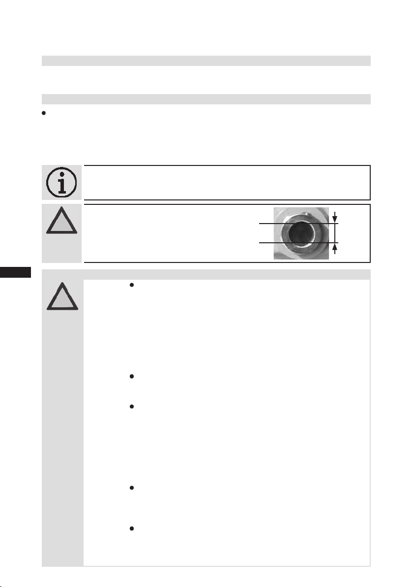
The oil level must be in the
visible part of the sight
glass; damage to the com-
pressor is possible if over-
filled or underfilled!
ATTENTION!max.
min.
0,7Ltr.
oil level
Fig. 4
~
~