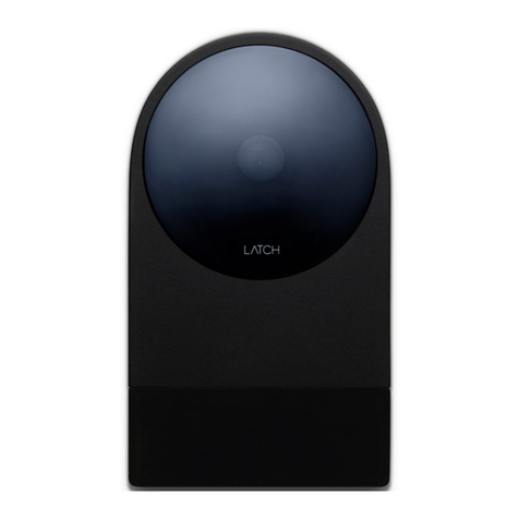
latch R SERIES User manual

INSTALLATION GUIDE
R SERIES

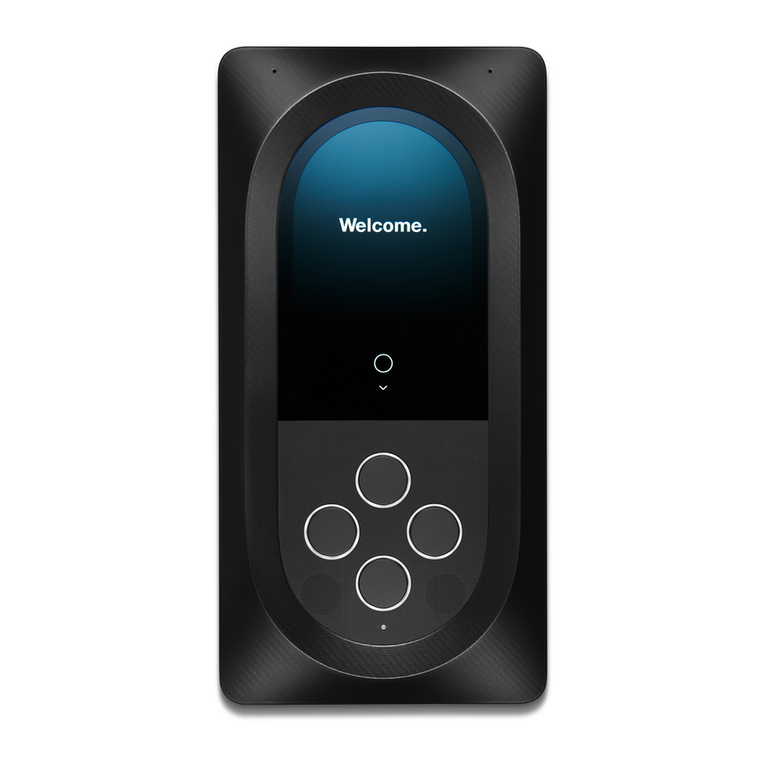
Latch R is a proximity reader, keypad, and wireless entry system,
that can be operated as a standalone device or be connected to a
panel as part of a wider system.
Welcome to your
smartest install yet.

Only use screws provided. Other screws can cause Latch R to
disengage from the mounting plate.
The relay will revert to an open state in the event of power failure.
Take precautions when wiring fail-safe locking hardware.
Apply power only after all devices have been properly connected.
Conguration requires the iOS Manager App running on an iPhone
5S or newer.
Troubleshoot at support.latch.com
Things you should know
1.
2.
3.
4.
5.

LATCH R Reader
VIN
GND
A/D0
B/D1
COM_GND
IO1
IO2
IO3
COM
NO/NC
12VDC - 24VDC
Supply
RJ45 Plug
Minimum Wiring Recommendations
Power
22AWG12V 20AWG 18AWG 14AWG
Relay 22AWG 20AWG 18AWG
22AWG24V 20AWG 20AWG 20AWG
< 50ftDistance < 500ft < 1000ft< 200ft
Wiring
Standalone Wiring

Request to Exit
Egress sensor
Door Lock
Door contact
sensor
Router

Power
22AWG12V 20AWG 18AWG 14AWG
Wiegand (Shielded) 22AWG 22AWG 20AWG20AWG
22AWG24V 20AWG 20AWG 20AWG
< 50ftDistance < 500ft < 1000ft< 200ft
12VDC - 24VDC
Supply
Panel Wiring
LATCH R Reader
VIN
GND
A/D0
B/D1
COM_GND
IO1
IO2
IO3
COM
NO/NC
RJ45 Plug
Minimum Wiring Recommendations
Wiring

Door contact
sensor
Egress sensor
Unlock +
Egress sensor
Elevator Control Panel
(only when using with
Elevator Floor Access)
Door Lock
Access Control Panel
Wiegand/RS-485
Router

Standard Reader Connections
Ethernet
Connections
Wire Color
GREEN
1
WHITE
2
GRAY
3
YELLOW
4
BLUE
5
ORANGE
6
PURPLE
7
BROWN
8
RED
9
BLACK10
Name Description
A/D0
B/D1
COM_GND
NO/NC
COM
IO1
IO2
IO3
VIN
GND
RS-485 A, Wiegand DATA0
RS-485 B, Wiegand DATA1
Return for A/D0, B/D1 wires
Relay contact
Relay contact
Input/Output
Input/Output
Input/Output
12VDC to 24VDC power input
Return for power input
Wire Color
GREEN/WHITE
11
GREEN
12
ORANGE/WHITE
13
BLUE
14
BLUE/WHITE
15
ORANGE
16
BROWN/WHITE
17
BROWN
18
Name
TX+
TX-
RX+
SPR1
SPR2
RX-
SPR3
SPR4
Wiring

Voltage dierence between GND and COM_GND should not exceed 25V
Rating
0.025A max drive, 5VDC
1.5A max, 24V DC
1.5A max, 24V DC
0.35A max sink, 24VDC max
0.5A /12VDC or 0.25A /24VDC
Reference
COM_GND
COM_GND
GND
GND
GND
GND
GND
GND

Mechanical
- Dimensions: 5.49” x 3.18” x 0.76”
Wireless Communication
- Near Field Communication (NFC): ISO 14443A
- NFC Card Type: Mifare Classic
- Bluetooth: BLE 4.2 (iOS and Android compatible)
- Wi-Fi: 802.11 b/g/n
Wired Communication
- Ethernet 10/100Mbps, RJ45 Plug
- Serial: RS-485, 5VDC
- Wiegand (26-bit) Data0, Data1, 5VDC 25mA source each
Power
- Class 2 Isolated, UL Listed Power Supply
- Supply Voltage: 12VDC to 24VDC
- Operating Power: 6W (0.5A @12VDC, 0.25A @24VDC)
Technical Specications
For UL 294 installations, the power source must be compliant to
one of the following standards: UL 294, UL 603, UL 864, or UL
1481. For ULC 60839-11-1 installation, the power source must
be compliant to one of the following standards: ULC S304 or ULC
S318.
DC input evaluated for UL294: 12V DC – 24V DC.
-
-

Interface
- 1 x Lock Relay: Congurable SPST NO
- 3 x Input or Output (input: normally low; output: open drain)
Camera
- 135 degree wide capture
Environmental
- Temperature: Operating / Storage -40°C to 66°C
- Operating Humidity: 93% at 32°C, non-condensing
- Environmental: IP65 | IK04
Compliance
- FCC Part 15 (US)
- IC RSS (Canada)
- UL 294
- UL/CSA 62368-1
- RoHS
Warranty
- 1-year limited warranty on electronic components
- 5-year limited warranty on mechanical components

3.28"
1.5"
3
16
" x 1 1/2"
2.00"
Prepare holes using mounting plate as a template and drill.
Drill

Important: Use the provided screws or #6
athead screws to avoid mounting failure.
Screw mounting plate in using the correct screws.
Screw

Connect based on wiring diagrams.
Connect

Download Latch Manager App from the iOS App Store
to congure Latch R and test that everything works.
Requires iPhone 5S or newer.
Learn more at support.latch.com
Congure

A
B
A. Insert bottom locking tab of mounting plate into
Latch R.
B. Place Latch R ush with mounting plate and slide
down until all mounting tabs t snugly.
Mount

Tighten security screw to secure.
Secure

Federal Communications Commission (FCC)
Compliance Statement
This device complies with part 15 of the FCC Rules. Operation is
subject to the following conditions:
(1) This device may not cause harmful interference and (2) this device
must accept any interference received, including interference that may
cause undesired operation.
CAUTION: Changes or modications not expressly approved by
the manufacturer responsible for compliance could void the user’s
authority to operate the equipment.
NOTE: This equipment has been tested and found to comply with
the limits for a Class B device, pursuant to part 15 of the FCC Rules.
These limits are designed to provide reasonable protection against
harmful interference in a residential installation. This equipment
generates, uses and can radiate radio frequency energy and if not
installed and used in accordance with the instructions, may cause
harmful interference to radio communications. However, there is no
guarantee that interference will not occur in a particular installation. If
this equipment does cause harmful interference to radio or television
reception, which can be determined by turning the equipment o and
on, the user is encouraged to try to correct the interference by one or
more of the following measures:
• Reorient or relocate the receiving antenna
• Increase the separation between the equipment and receiver
Regulatory Compliance

• Connect the equipment into an outlet on a circuit dierent from that
to which the receiver is connected
• Consult the dealer or an experienced radio/TV technician for help
Industry Canada (IC) Compliance Statement
Operation is subject to the following two conditions:
1. This device may not cause interference, and
2. This device must accept any interference, including interference
that may cause undesired operation of the device.
To satisfy RF exposure requirements, this device and its antenna must
operate with a separation distance of at least 20 centimeters from all
persons and must not be colocated or operating in conjunction with
any other antenna or transmitter.
Le présent appareil est conforme aux CNR d’Industrie Canada
applicables aux appareils radio exempts de licence. L’exploitation est
autorisée aux deux conditions suivantes :
1. l’appareil ne doit pas produire de brouillage, et
2. l’appareil doit accepter tout brouillage radioélectrique subi, même si
le brouillage est susceptible d’en compromettre le fonctionnement.
Pour remplir les conditions requise sur l’exposition des fréquences
radios, cet appareil et les antennes doivent fonctionner avec une
distance minimum de 20 centimètres avec toutes les personnes et ne
doivent pas être placés ou fonctionner en conjonction avec tout autre
antenne ou émetteur.

Safety instructions
This product shall be installed and serviced by certied
professionals only.
The product is intended to be used as either a standalone access
control system or as a reader with a panel. Multiple Latch R devices
cannot be used to control a single access point.
Locations and wiring methods shall be in accordance with the
National Electrical Code, ANSI/NFPA 70.
There are no replacement parts available for this product.
Outdoor electrical boxes used for mounting are recommended to
be NEMA 3 or better.
Correct wiring insulation should be used during installation to
prevent the risk of electrical shock.
For UL compliant installations, UL requirements listed in this manual
supersede conicting information.
•
•
•
•
•
•
•
Testing and Maintenance Operation
•
•Loose wiring & loose screws.
Normal operation (attempt to unlock with all possible methods).
Prior to installation, ensure that all wiring is secure. Each unit should
be checked annually for:
Impaired Operation
Units are designed to operate under adverse environmental conditions.
Under normal circumstances, they will function properly regardless
of outside conditions. However, units do not have secondary power
sources and cannot function without direct continuous power. If a
unit is damaged by natural causes or deliberate vandalism, it may not
function properly depending on the level of damage.
Other manuals for R SERIES
1
Table of contents
Other latch Intercom System manuals
Popular Intercom System manuals by other brands

Somogyi Elektronic
Somogyi Elektronic Home DPV 22 instruction manual

Aiphone
Aiphone LEF-10 Installation & operation manual

Panasonic
Panasonic VL-SW251BX operating instructions

Telex
Telex BP-325 user manual

ACT
ACT ACTPRO PRODUCT RANGE Operating and installation instruction

DoorBird
DoorBird D10x Series installation manual