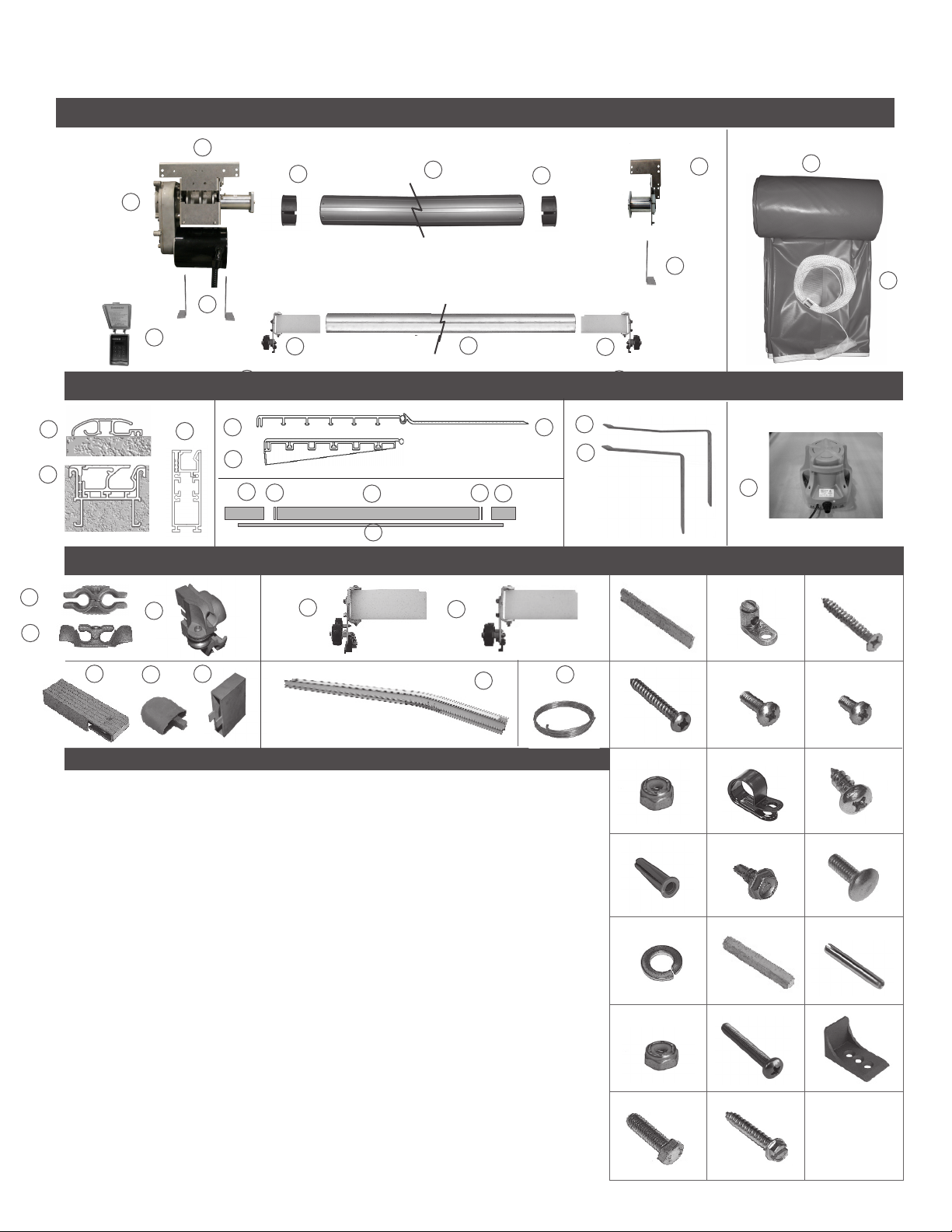
Latham CS300HD User manual

CS300HD/CS3000LO System
A U T O M A T I C S A F E T Y POOL C O V E R
Recessed Top Track Installation Guide

Automatic Safety SpaCover
The CS300HD Auto Safety SpaCover is a system that can be installed in cover boxes that have a width between 10 - 14 inches,
including our polymer housing. It also offers lower offsets than the full sized Eclipse system. This mechanism is designed to
cover spas and small pools up to 12 x 24 or smaller for CS300HD systems or 16 x 32 or smaller for CS3000LO systems.
It can be used in Under Track, Deck Mount, or Recessed Top Track applications. Be sure to read through all of the system
requirements in regards to the pool construction, cover box, drainage, and electrical BEFORE you install this system.
SECTIONS
Parts Reference................................................................................... 3
Standard Top Track........................................................................... 4
Recessed Horizontal / Slim Flush..................................................7
Mechanism .......................................................................................... 9
Cover Fabric...................................................................................... 13
Home Owner Checklist................................................................... 17
Tools Required
1. Hammer drill or rotary hammer
2. Masonry drill bit 1/4” x 6” (1/4” x 12” bit)
3. Extension cords
4. #2 and #3 Phillips & standard screw drivers
5. Ratchet with 5/16” - 3/4” sockets
6. Hacksaw
7. String line
8. Utility knife
9. Broom
10. Hammer & rubber mallet
11. Pliers - standard, needle nose & channel lock
12. Files - round, triangular & flat
13. Lighter
14. Carpenter’s square
15. 5/16” hex head driver bit with 12” extension
16. Drill (cordless or corded)
17. Set of drill bits (1/4” down to 1/16”)
18. Crescent wrench
19. 100 & 25 foot Tape Measure
20. Chalk line ( use white chalk)
21. Nut drivers - 5/16”, 3/8”, 7/16”, 1/2”
22. Chisel (wood & concrete)
23. Scissors
24. Wire strippers
25. Set of box/open end wrenches - 5/16” - 3/4”
26. 6” level
27. Set of allen wrenches
28. Wire
29. Electrical tape
30. Small sledge hammer
31. Vice grips
32. #2 #3 Phillips drill bits
33. Pencil or marker
34. 6 - 8 clamps
Optional Power tools
Skill saw with carbide tipped blade
Sawzall, Grinder, Angle drill
© Latham Pool Products, Inc. 2018. All rights reserved.
Calibrate Touch Pad Control Switch ......................................... 18
2 of 19
Installation Check List .................................................................... 19

Parts Reference
Mechanism Components
1
Cover Fabric
2
7
54
3
4
77
8
10
11
3
1. A0615 Motor Asm CS300HD w/ Face Plate
2. A2341 Mechanism RT or UT(Right)
A2331 Mechanism RT or UT(Left)
3. M8433 Mechanism Mounting Foot
4. M9682 Composite Tube Insert - 6 inch
5. X0673 Roll-up Tube 6 in extruded anodized 20 ft.
6. A2342 Non-motor end assembly RT/UT(Right)
A2338 Non-motor end assembly RT/UT(Left)
7. A2469-A Standard Touch Pad Control Switch
8. A1565 Wheel Assembly (standard top track)
9. X0021 Aluminum leading edge
10. Cover fabric
11. Varies PowerFlex rope - Lengths will vary by cover
12. X0656 Standard Top Track
13. A2123 Horizontal Flush Deck Track
14. A0021 Slim Flush Track and Housing
15. X0004 Main Lid
16. A0376 Lid wedge
17. X0121 Motor End lid
18. X0659 Non-motor end lid
19. X0943 8” lid hinge
20. A1698 14” cover lid bracket (Set of 2)
21. A1694 12” cover lid bracket (Set of 2)
22. E1130 Little Giant cover pump & instructions
23. A1071 Guide feed for standard top track
24. A1061 RHTGuide Feed and Stop
25. A0006 Slim Flush Guide Feed & Pulley
26. A2198 Wheel Assembly (Recessed Horizontal Track)
27. A0886 Pulley End (standard top track)
28. A2141 Pulley End (recessed horizontal track)
29. A0005 Slim Flush End Pulley Assembly
30. A2133 Curved track, housing, stop, splice - 3 ft.
31. E1098 Bonding wire
32. M3962 Track splice RHG
33. E1086 Bonding lug ka-6u (for 1 wire)
34. H0334 Screw PFSM 12 x 1-3/4 for Top Track
35. H0332 Screw PPSM 12 x 1-3/4 for lid hinge
36. H0150 Screw PPMS 10-32 x 5/8, for cross brace
37. H0152 Screw PPMS 10-32 x 1/2
38. H0176 Nut nylock 10-32
39. H0075 Rope loop (black plastic)
40. H0310 Screw PPSM 10 x 1/2
41. H0324 Plastic anchor STD #12
42. H0331 Screw HHWSM Tek 10 x 1/2 SS
43. H0096 Carriage bolt 1/4-20 x 1/2 SS
44. H0006 Washer split lock
45. M0105 Standard splice, top track
46. H9630 Spring pin for track alignment
47. H0276 Nylock nut 1/4 - 20
48. H1101 Screw 10- 32 1-3/8”
49. M9797 Stop Top Track 403, L Shaped Stainless Steel
48. H0096 Bolt 3/8-16- 1-1/4
49. H0331 Screw HHWSM 12 x 1-1/2 w/slot
50. H0096 Bolt HH 3/8-16 x 1-1/4
51. H0331 Screw HHWSM 12 x 1-1/2 with slot
Misc. Hardware
Standard Top Track Lid Components Lid Support Bracket Cover Pump
15
22
20
19
9
8
Cover Track Types
8
17 15 18 Top view
Side view
Guide Feed Wheel Assemblies
16
16
16
21
826
36
46
39 40
43
37
42
45
35
38
41
44
47
50
48
51
49
32 33 34
30 31
Parts List
19
13
12 14
23
24
25
28
6
27 29
© Latham Pool Products, Inc. 2018. All rights reserved.
3 of 19

Step By Step Instructions
STANDARD TOP TRACK
Step By Step Instructions Page/Step
Standard top track installation............................5/1
© Latham Pool Products, Inc. 2018. All rights reserved.
4 of 19

Step By Step Instructions
To determine if the cover system was
ordered correctly for the pool, the length of
the roll-up tube should be 3 inches shorter
than the track space. For example, for an 16
foot track space, the correct length of roll-
up tube is 15 ft 9 in.
Cut the length of the track on each side of
the pool so it will extend 1 inch past the
inside edge of the cover box at the
mechanism end.
123
45
8
Position the cover track along both sides of
the pool. The lengths, widths and diagonal
measurements must be equal to each other
for the automatic cover system to operate
properly. Mark where the center of the
track will be on the pool deck.
6
9
7
Splicing the Tracks Together
Before splicing the sections of track together,
file all track ends thoroughly, rounding all
edges and removing all burrs. This step
is extremely important. The cover can be
damaged very easily by metal burrs and this
damage is not covered by the warranty.
Tap the spring pin (46) into the round
splice channel. Slide the center splice (45)
into the center channel.
Join the track sections together by hand.
At one end, use a rubber mallet to tap the
track sections together.
The two sections of track should be tight
together.
Cutting the Tracks to Length
With tracks extended 1 inch into the cover
box at the mechanism end, cut the tracks
so they extend 18” past the waterline at
the opposite end of the pool.
© Latham Pool Products, Inc. 2018. All rights reserved.
Numbers in parenthesis refer to hardware shown on page 3.
5 of 19

Step By Step Instructions Numbers in parenthesis refer to hardware shown on page 3.
Checking for Square
Measure the track space, track length
and diagonals to make sure the
tracks form a perfect rectangle.
Cut the track at the mechanism end to the
proper length using a miter saw. It is
important to have square cuts on the track.
Note: Always wear safety goggles when
using powered equipment.
File the track ends on both sides of the pool
making sure to round all edges and remove
all burrs. This step is extremely important.
The cover can be damaged very easily by
metal burrs and this damage is not covered
by the warranty.
Attaching the Tracks to the Deck
Place the tracks into position on the deck in
the marked positions. Make sure that the
tracks run completely straight on both sides
of the pool. Drill through the pre-drilled track
holes into the deck. Drill at least 3” deep. For
wood or acrylic decks, pre-drill a 3/16” hole,
then use screws to secure the track to the
deck.
Move the tracks to the side to expose the
holes in the deck. Clean the dust from each
hole and tap plastic anchors (41) into each
one.
Place the track back over the holes in the
deck. Fasten the track screws (34) halfway
through the tracks into the plastic anchors.
The screws will be fastened completely
later in the installation.
10 11 12
13 14 15
© Latham Pool Products, Inc. 2018. All rights reserved.
6 of 19

RECESSED HORIZONTAL TRACK / SLIM FLUSH TRACK
Components & Installation Guidelines Page
System components & installation guidelines ......8
© Latham Pool Products, Inc. 2018. All rights reserved.
7 of 19

System components
1. Both Recessed Horizontal and Slim Flush Tracks consist of 3 parts,
the track housing, the track, and the locking strip.
2. End pulley assembly - This can either be installed when the
housing is installed or at the time the mechanism is installed.
3. Track protector: It is important to protect the track while the
concrete deck is being poured. This can be done either by using
10 mill plumbing tape or using an optional track protector that is
available for recessed horizontal track (X0865).
Installation Guidelines
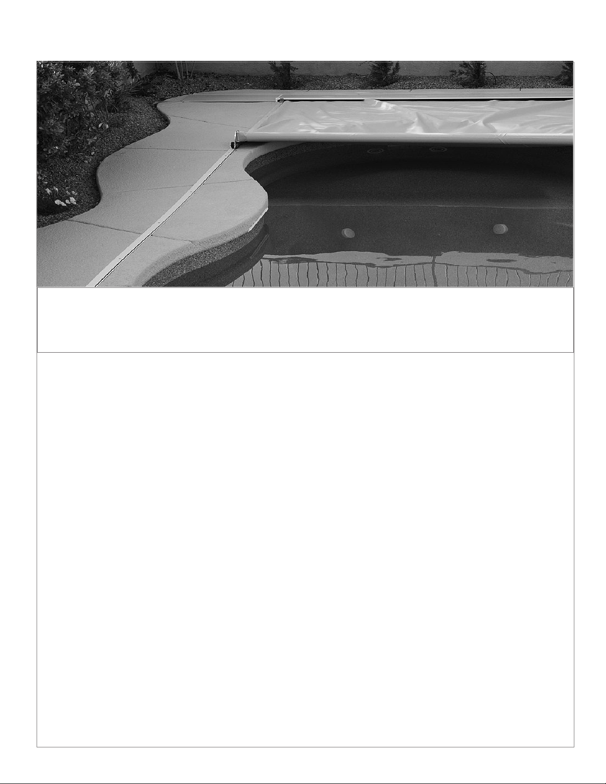
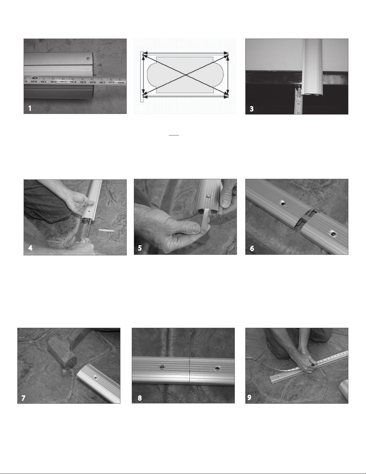
1. The installed tracks must start flush with the inside of the cover
box, which must be a minimum of 12 inches from the end of the
pool and extend 18 inches beyond the other end of the pool.
The tracks must form a perfect rectangle. The track lengths, the
distance between the tracks and the diagonals each must be
equal.
2. The tracks must be installed exactly at nished deck grade. It is
strongly recommended that the deck be kept level from the pool
to the track housings. Start the slope outside of the tracks. Note:
the deck around the cover housing boxes should be flat for a
minimum of 4” before starting any slope if a standard lid is to be
used.
3. The housing must have the track, a spacer (standard spacer or
optional plastic protector) and top protection in place before
pouring deck.
4. There are several ways that the tracks can be installed. In each
case track supports / mounting feet must be no further than 5’
apart.
a. Set in place using the mounting feet kit (A3031 for Slim
Flush Track. A1531 for Recessed Horizontal Track)
b. Mounted on top 2 x 4 stakes, which are left in the deck
permanently. Attach housing to the stakes with self-tapping
screws or by drilling holes in the housing and using drywall
or deck screws.
c. Set into piles of concrete or gunite approximately every 4
feet. If this method is used, care must be taken to make
sure that no cement is left higher than the bottom of the
side of the channel. Otherwise it will have to be chipped
down before the deck is poured.
5. Regardless of how the tracks are installed, it is recommended that
a string line be left in place until after the pour.
6. The standard installation is with straight track;however, optional
curved pieces of recessed horizontal track are available if flush
deck lid is to be used. In this case, the deck is lowered 2” between
the tracks and the box is installed 2” lower.
7. It is recommended that a minimum width of 5 to 6 inches of
concrete be poured on each side of the housing. Rebar or
concrete wire under the housing will help eliminate the concrete
cracking and separating from the housing.
8. It is recommended that you put a strike joint off the end of your
track to control the shrinkage crack.
9. To avoid concrete flaking when the protector is removed, go down
each side with a 1/8-radius edger. For proper cover operation,
concrete must be as close to the top of the housing as is possible
10. Some builders find that it is easier to keep the tracks clean if they
install Deck-O-Drain channel between the end of the housing and
the end of the deck. However, this is optional.
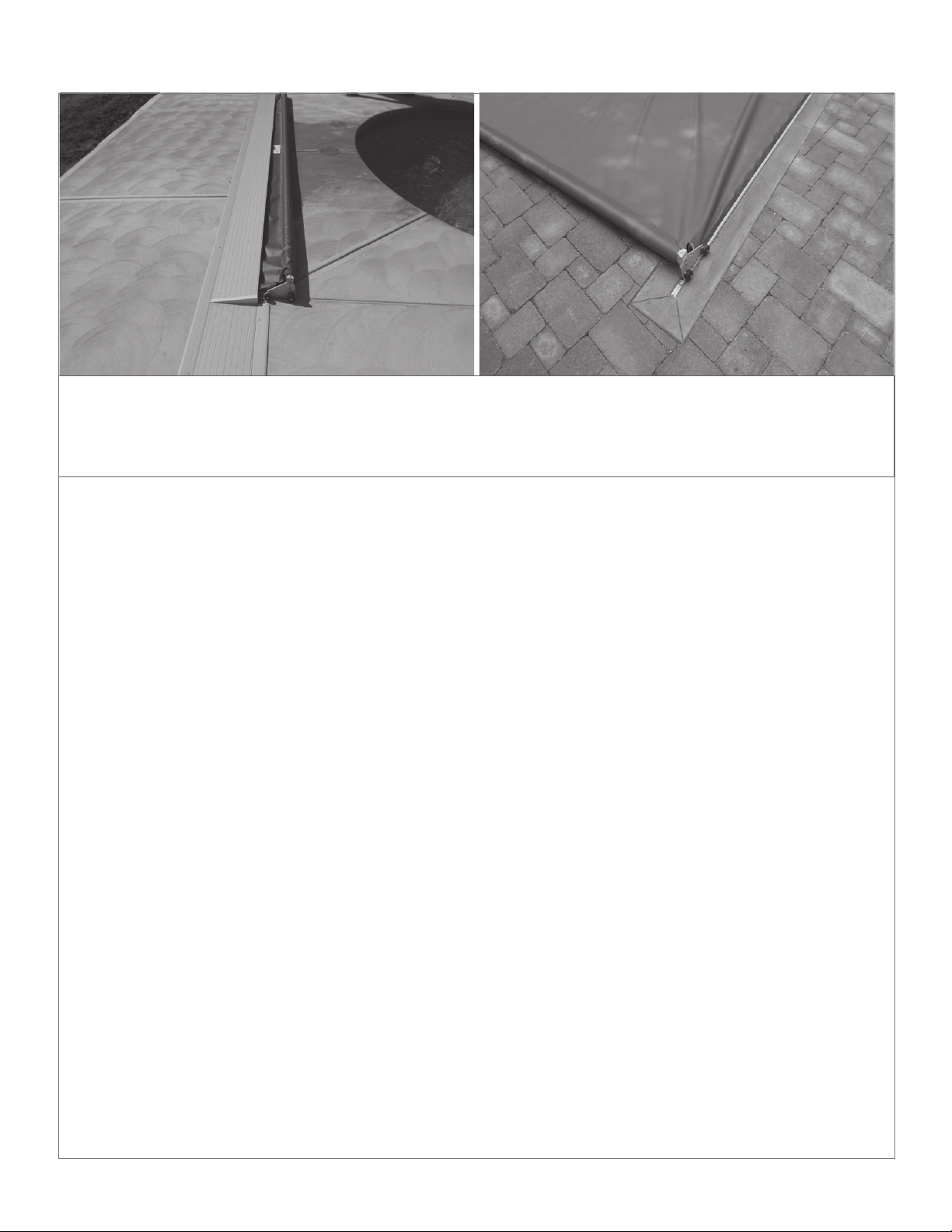
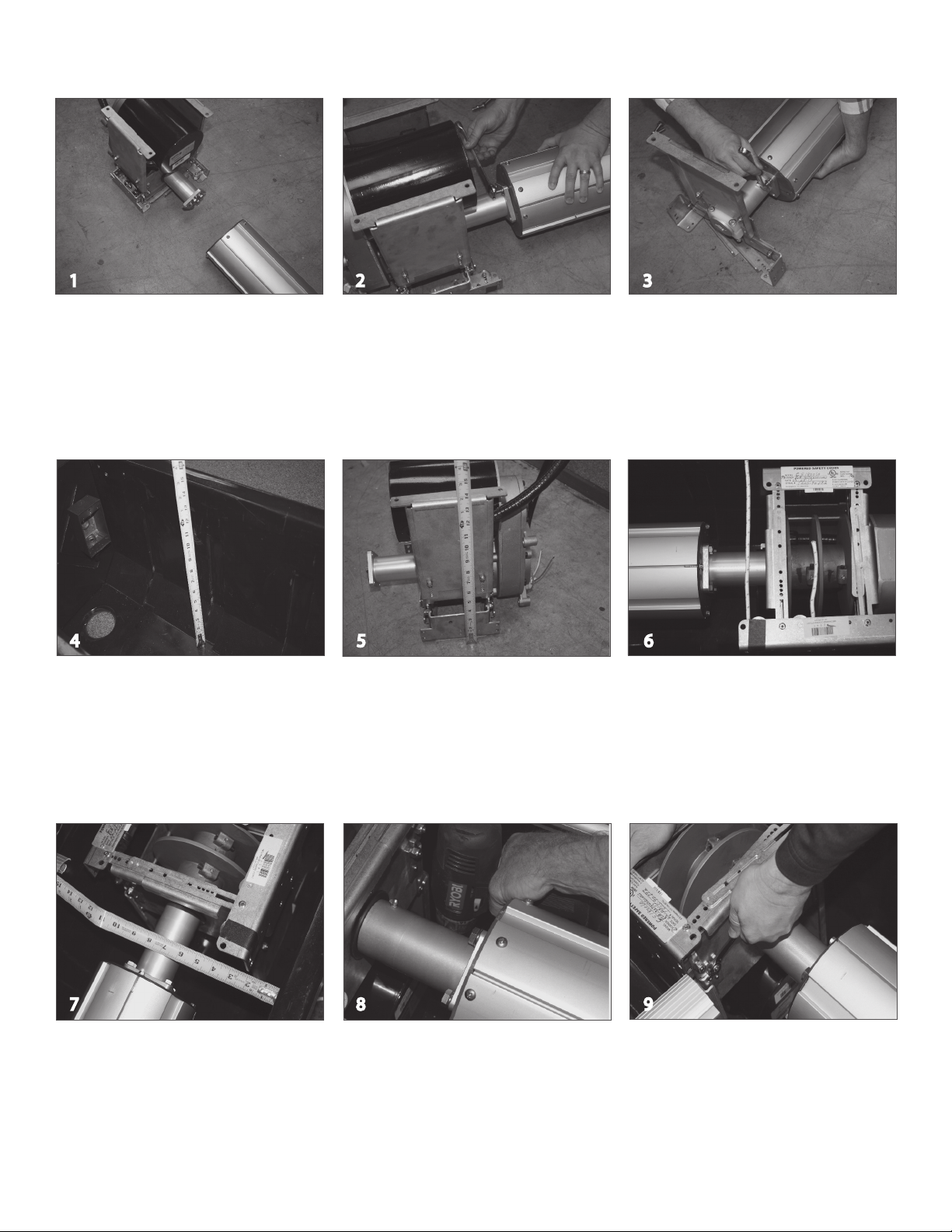
(4.a.) Track staked in place, ready for pour
(4.b.) Housing in place mounted on gunite piles ready for
deck pour.
Slim Flush Track with Track,
Housing and Spacer
(6) OPTION: Recessed horizontal track sloped into the
box. Purchase set of curved tracks for housing end of
track. Bend begins 15”in front of housing. Make sure
top of track is minimum of 1”lower than bottom of lid.
Recessed Horizontal Track
with Track, Housing and
Spacer
(4.a.) Track staked in place using the optional
mounting feet, ready for pour
© Latham Pool Products, Inc. 2018. All rights reserved.
8 of 19

MECHANISM
Step By Step Instructions Page/Step
Assembling the mechanism................................. 10/1
Installing the mechanism
in the cover box......................................................... 10/6
Wiring the touch pad control switch..................... 12
Electrical wiring and bonding................................... 12
(4.b.) Housing in place mounted on gunite piles ready for deck pour.
© Latham Pool Products, Inc. 2018. All rights reserved.
9 of 19

Step By Step Instructions Numbers in parenthesis refer to hardware shown on page 3.
Assembling the mechanism
Turn the motor and non-motor end upside
down. This is done to appropriately attach
the roll-up tube and the mechanism
mounting feet.
Attach the roll-up tube to the non-motor end
of the mechanism using the 3/8” x 1-1/4”
bolts (44) and lock washers (50) provided.
To attach the feet, first measure the distance
from the bottom of the cover box to the
bottom of the track.
(This will determine the height of the
mechanism.)
Attach the mechanism feet to the
mechanism approximately 1 inch less than
the distance from the bottom of the cover
box to the top of the track/retainer. Use a
7/16 inch ratchet to tighten bolts.
Tip: The roll-up tube should be set as high
as possible without allowing the cover rub
on the lid brackets.
Installing the mechanism in the
Cover Box
Line up the mechanism with the track so
the rope will come straight out and around
the motor end pulley.
Center the tube in the cover box. Tip: If the
pool is not square, square up the mechanism
with the track.
Attach the mechanism feet to the floor of
the cover box. Use the mounting hardware
provided.
12 3
45 6
78 9
Loosen the four nylock nuts on the pulley
brackets. Raise the pulley bracket assembly
so it is level with the bottom of the track.
Attach the roll-up tube to the motor end of
the mechanism using the 3/8” x 1-1/4”
bolts (44) and lock washers (50) provided.
© Latham Pool Products, Inc. 2018. All rights reserved.
10 of 19

Step By Step Instructions
Anchor the non-motor side of the mechanism
into the cover box in as many places as
possible. Use the appropriate screws and
anchors depending on the type of cover box
being used.
With the brackets on the non-motor end in
position, place a small level across the
brackets to make sure they are level with
the bottom of the track. Tighten the nylock
nuts on the adjustable brackets.
With the brackets in position, place a small
level across them to make sure they are level.
Tighten the four nuts on the adjustable
motor end brackets.
12
18
Loosen the bolts on the adjustable brackets
on the non-motor end of the mechanism.
Spread the pulley brackets outward against
the walls of the cover box.
Anchoring the Pulley Brackets
Anchor the motor mechanism brackets into
the cover box in as many places as possible.
Use the appropriate screws and anchors
depending on the type of cover box being
used.
On the motor and non-motor side, use the
half inch screws (37) and nylock nuts (47)
provided and secure the cross braces
together.
10 11
13 14 15
Attach the #8 copper bond wire that is
stubbed into the cover box to the
bonding lug on the motor end of the
mechanism.
Make the same connection with the #8
copper bond wire that is in the cover box
on the non-motor end of the mechanism.
16 17
© Latham Pool Products, Inc. 2018. All rights reserved.
Numbers in parenthesis refer to hardware shown on page 3.
11 of 19

Electrical Wiring & Bonding
The system must be bonded to meet the National Electrical Code. Bond both tracks to the mechanism by attaching a bonding lug to the
guide screw and running a #8 solid copper bond wire to the mechanism. Bond the lid to the mechanism by drilling a hole in the lid at
either end of the lid and attaching a bonding lug in each position and bonding it to the mechanism. All brackets and any other metal over
4” long should likewise be bonded to the mechanism. There should be a bond wire from the equipment pad inside the cover box. Attach
this bond wire to the mechanism to complete the bonding requirement. Note: Builder is responsible to bring proper electrical lines, conduit
and bonding to the mechanism. Electrical wiring diagram and details are shown below.
Wiring the Electrical Switch
The control switch mustbe mounted in an all-weather box, in a location where 100% of the pool is visible.
Connect the control switch according the diagram below.
© Latham Pool Products, Inc. 2018. All rights reserved.
12 of 19

COVER FABRIC
Step by Step Instructions Page/Step
Opening the cover box ........................................... 14/1
Running the rope through the track.................. 14/4
Routing the ropes................................................... 15/10
Attaching the ropes to the reels.........................16/30
Pinning the cover to the tube..............................16/32
© Latham Pool Products, Inc. 2018. All rights reserved.
13 of 19

Step By Step Instructions Numbers in parenthesis refer to hardware shown on page 3.
Rolling Out the Cover
Standing behind the housing looking over
the pool, unroll the cover from left to right.
Unwrap the ropes and run them through the
tracks.
Running Ropes Through the tracks
The preferred method of running the rope is
to pierce the rope with a 1’ length of wire and
use it as a handle to feed the rope through the
track.
Hold the wire with some pliers and pull the
rope down the length of the track toward
the end of the pool.
Feed the rope through the pulley assembly
(28) and place the pulley housing onto the
end of the track.
Feed the rope into the back channel then
pull the rope down the back side of the
track toward the cover housing.
Pull all excess rope through the cover track.
2 3
45 6
78 9
Complete the fastening of all track screws
flush to the top of the track and fasten the
pulley screw on both sides of the pool.
Clean concrete dust from tracks and pulley
endcap. Make sure ALL screws are flush with
tracks.
Opening the Cover
To open the cover box, cut the bands that
hold the two halves of the box together.
Never cut the top of the box open. Doing
this could easily damage the cover inside.
This kind of damage is not covered under
the fabric warranty. With the bands cut, lift
and remove the top box.
1
© Latham Pool Products, Inc. 2018. All rights reserved.
14 of 19

Routing the Ropes
Begin on the motor end of the mechanism.
Run the rope from the track so it travels
straight from the track to the first pulley.
Extend the rope out the back side of the
pulley.
On the non-motor end, feed the rope
around the pulley of the non-motor end
pulley bracket. Pull the rope through to the
motor end.
Feed the non-motor end rope behind the rst
and second and third horizontal pulleys.
Pull the rope around the vertical pulley on the
front wall of the cover box.
On the motor end, feed the rope around
the first and second horizontal pulleys on
the back wall of the cover box.
Pulll the rope around the vertical pulley on
the front wall of the cover box.
10 11 12
13 14 15
Run the rope from the non-motor end
along the backside of the cover box. The
rope should run through the rope loops
(39) to keep it from getting caught in the
cover. Space the rope loops evenly across
the back of the cover box.
16
The cover must be open when cutting and
attaching the ropes. Pull the cover back
until the sliders are against the guides. Pull
the ropes tight as they come off the pulleys
on the mechanism to eliminate the slack in
the rope.
While pulling both ropes tight, use a lighter
or torch to burn the rope in the location it
will be cut. This will help them not fray after
they have been cut. Cut the ropes so they
are at least 8 ft long. Use the lighter to
reburn the cut ends of the rope if needed.
17 18
© Latham Pool Products, Inc. 2018. All rights reserved.
Numbers in parenthesis refer to hardware shown on page 3.
Step By Step Instructions
15 of 19

Step By Step Instructions Numbers in parenthesis refer to hardware shown on page 3.
Attaching the Ropes to the
Rope Reel
Attach the rope to the rope reel. Guide the
ropes onto the rope reel while operating
the key switch in the cover position.
Tip: The rope for the non-motor side should
be attached approximately 1 inch further
down than the motor side rope depending
on the width of the pool. Use the switch
and operate the cover in the “Closed”
position to cover the pool.
Pinning the Cover to the
Roll-up Tube
Using a self-tapping screw (42), attach the
bonding wire on both sides of the roll-up
tube.
23
20
Find the center of the slack and pin directly
to the tube (DO NOT FOLD THE SLACK).
Repeat this step several times along the tube.
This will help to distribute the slack across
the roll-up tube evenly.
Tip: Use the weld line on the tube to help pin
the cover straight on the tube.
Make sure that the cover and the webbing roll
up nice and even around the roll-up tube.
Operate the cover 6-10 times to and make any
adjustments to the rope reel brake and roll-up
tube brake if necessary.
The CS300HD installation is complete.
19 21
22
Using a self-tapping screw (32), line the cover
up straight as it comes out of the track and pin
the cover to the roll-up tube on both sides.
© Latham Pool Products, Inc. 2018. All rights reserved.
16 of 19

HOME OWNER CHECKLIST
After the cover system is installed, it is critically important
to instruct the home owner on how to operate the cover
system safely and do routine maintenance. Use the
following check list and the Coverstar Use & Care Guide as
your primary instruction source.
Use & Care Guide Page
How to use the cover pump ...................................................4
How to uncover and cover the pool................................6-7
Warn about standing water on the cover..........................4
Who is authorized to operate the cover system..............6
Pool chemicals and cover life.................................................8
Proper maintenance and care of the cover system....8-9
Inform the customer on pool safety.................Back cover
© Latham Pool Products, Inc. 2018. All rights reserved.
17 of 19

18 of 19
© Latham Pool Products, Inc. 2018. All rights reserved.
Calibrate Touch Pad Control Switch
The touch pad can be calibrated for the specific pool it is installed on. This calibration will teach the touch
pad what the electrical current consumption is (for retrofit models) and what the transit operation time
will be in normal operation. The touch pad utilizes this information to determine over currents and cycle
calculations.
1. Access the service menu using the service passcode.(5991)
2. Press the Service button. The display will alternate between showing the “service contact
information” and “Press Select (5) for Menu”.
3. Press Select (5).
4. Press the down arrow (8) until“Calibrate Pool” is visible. Press the Select (5) button to
select this option.
5. Operate the cover until it is in its fully uncovered position.
6. Press Select (5) to conrm that the pool is completely uncovered.
7. Operate the cover until it is in its fully covered position.
8. Press Select (5) to conrm that the pool is completely covered.
9. Operate the cover until it is in its fully uncovered position.
10. Press Select (5) to conrm that the pool is completely uncovered.
11. The display will show the amp draw and time of operation for both covering and
uncovering the pool. Press Select (5) to accept these measurements.
Adjust Current Limits:
The touch pad retrofit model supports electronic current limiting. The default current settings are 7.5
Amps. The system will actively monitor operation of the cover and stop the system if current exceed
150% of the above value. To adjust these settings do the following:
1. Access the service menu using the service passcode (5991)
2. Press the Service button. The display will alternate between showing the “service contact information"
and "Press Select (5) for Menu".
3. Press Select (5).
4. Press the down arrow (8) until “Current Limits” is shown. Press the Select (5) button to select this option.
5. The display will show the average amp readings while opening the cover and the current limit setting
for opening the cover.
6. To change the average amp reading, press the up arrow (2) or down arrow (8) buttons. Press Select (5)
to advance the curser to the limit setting.
7. To adjust the limit setting, press the up arrow (2) or the down arrow (8) buttons. Press Select (5) to save
the new settings.
8. Make the same adjustments for the settings for closing the cover.
9. Press Select (5) to save the new amp and torque settings and return to the service screen.
Press the service button at any time to cancel the process

19 of 19
© Latham Pool Products, Inc. 2018. All rights reserved.
Tracks
qDoes the track space measurement match how the cover system was ordered?
qAll track ends filed. This is extremely important.
qCover goes through the track joints smoothly.
qAll track screws are tight and ush.
qPulleys are flush against the end of the track.
qThe guide feeds are snug against the track.
qGuide feeds bolted in and are tight.
qStops installed.
qAlignment pins and splices used when joining the tracks, even in encapsulation.
Mechanism
qMechanism installed level in the box.
qRoll-up tube level in cover box.
qTube centered between the tracks.
qEnough clearance top, bottom, sides for the fabric. No rubbing of webbing on sides or bottom of box.
qTube at the right height? The ideal location is to install the cover in the box so that the cover is coming o at as
small an angle as possible. This reduces stress on the mechanism and reduces wear on cover tracks at the end of
the track.
qTube either centered in the box or positioned slightly more towards the back of the box, so that the cover is unlikely to
qSystem mounted at right angle to the track.
qRopes coming back straight out of the track. An excessive angle will cause wear on the cover tracks at the end of
the track.
qRopes are not rubbing on any brackets or the deck.
qRopes are run correctly.
q8 feet of rope left on rope reel.
qSystem bonded according to electrical code. Cover bonded to leading edge and roll-up tube.
qMake sure there is adequate drainage from the cover box.
Cover
qFabric pinned to the roll-up tube without pinned folds.
qCover runs smoothly.
qCover properly aligned when it closes or retracts. Note: An inch or two out of square is not uncommon and is
not a concern as it will not affect the operation of the cover. Because of the size of the fabric roll and changes in
operating conditions the cover may vary slightly in alignment as it is run.
qThe leading edge inserts move in and out freely the whole length of the pool.
qFabric is pinned to the leading edge ush with the ends of the tube.
qCover not rubbing in the cover box as it rolls up.
Cover Lid
qAll sharp edges have been filed.
qAll areas where the lid is not flat on the deck have been screwed down to eliminate any potential hazards.
qThere is enough clearance between the lid brackets and the cover to avoid rubbing.
Misc.
qKey switch is in full view of the pool.
qCover pump tested by putting it in the water and operate it in front of homeowner.
qThe cover box is clean and clear of debris so that the drains are not easily clogged.
qPool area cleaned up.
qHomeowner has been instructed on the operation of the automatic safety cover system.
Installation Check List
rub on front of the box.
L0408 Updated 10/26/18 bm
This manual suits for next models
1
Table of contents
Other Latham Swimming Pool manuals