Lauda AL 2 User manual

2SHUDWLQJLQVWUXFWLRQV
/$8'$$TXDOLQH


Read the instructions before starting work!
Translation of the original operating instructions
LAUDA DR. R. WOBSER GMBH & CO. KG
Pfarrstraße 41/43
97922 Lauda-Königshofen
Germany
replaces release 04/2016 b, 06/2012, 05/09, 03/09,
03/07
YACE0086
Telephone: +49 (0)9343 503-0
Fax: +49 (0)9343 503-222
E-mail info@lauda.de
Internet http://www.lauda.de
Aqualine water baths
LAUDA AL 2
LAUDA AL 5
LAUDA AL 12
LAUDA AL 18
LAUDA AL 25
Operating instructions
Release 03/2018c,


Aqualine
15.03.18/ YACE0086 Prefixed safety notes 5
Prefixed safety notes
Before operating the equipment please read carefully all the instructions and safety
notes. If you have any questions please phone us!
Follow the instructions on setting up, operation etc. This is the only way to avoid
incorrect operation of the equipment and to ensure full warranty protection.
Transport the equipment with care!
Equipment and its internal parts can be damaged:
by dropping,
by shock.
Equipment must only be operated by technically qualified personnel!
Device must not be used with any other liquid than water.
Never operate the equipment without sufficient water level!
Do not start up the equipment, if:
it is damaged or leaking,
the supply cable is damaged.
Switch off the equipment and pull out the mains plug for:
servicing or repair,
before moving the equipment!
Drain the bath before moving the equipment!
Do not make technical modifications to the device.
Have the equipment serviced or repaired by properly qualified personnel only!
The Operating Instructions include additional safety notes which are identified by a triangle with
an exclamation mark. Carefully read the instructions and follow them accurately! Disregarding the
instructions may have serious consequences, such as damage to the equipment, damage to
property or injury to personnel.
We reserve the right to make technical alterations!

Aqualine
6Contents 15.03.18/ YACE0086
Contents
1SAFETY NOTES...........................................................................................................................................7
1.1 GENERAL SAFETY NOTES ..........................................................................................................................7
1.2 OTHER SAFETY NOTES..............................................................................................................................8
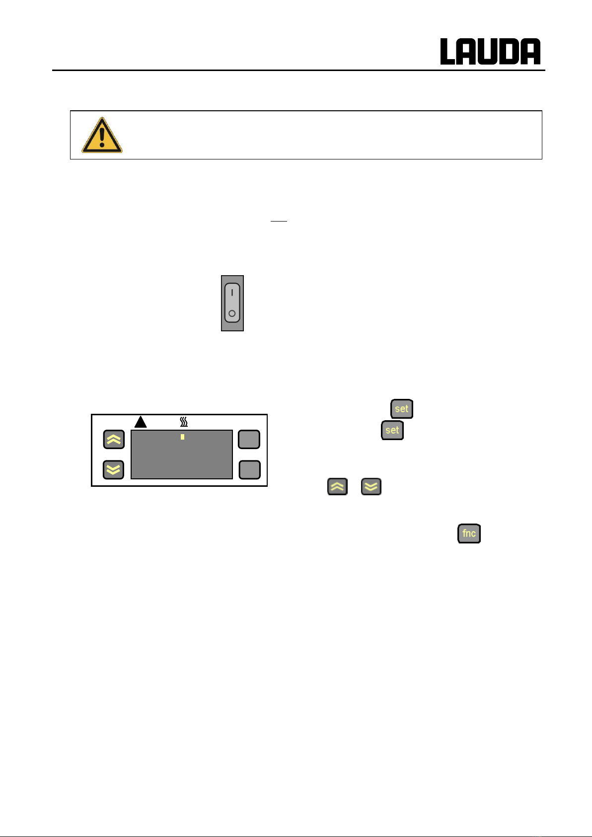
2BRIEF OPERATING INSTRUCTIONS .........................................................................................................9
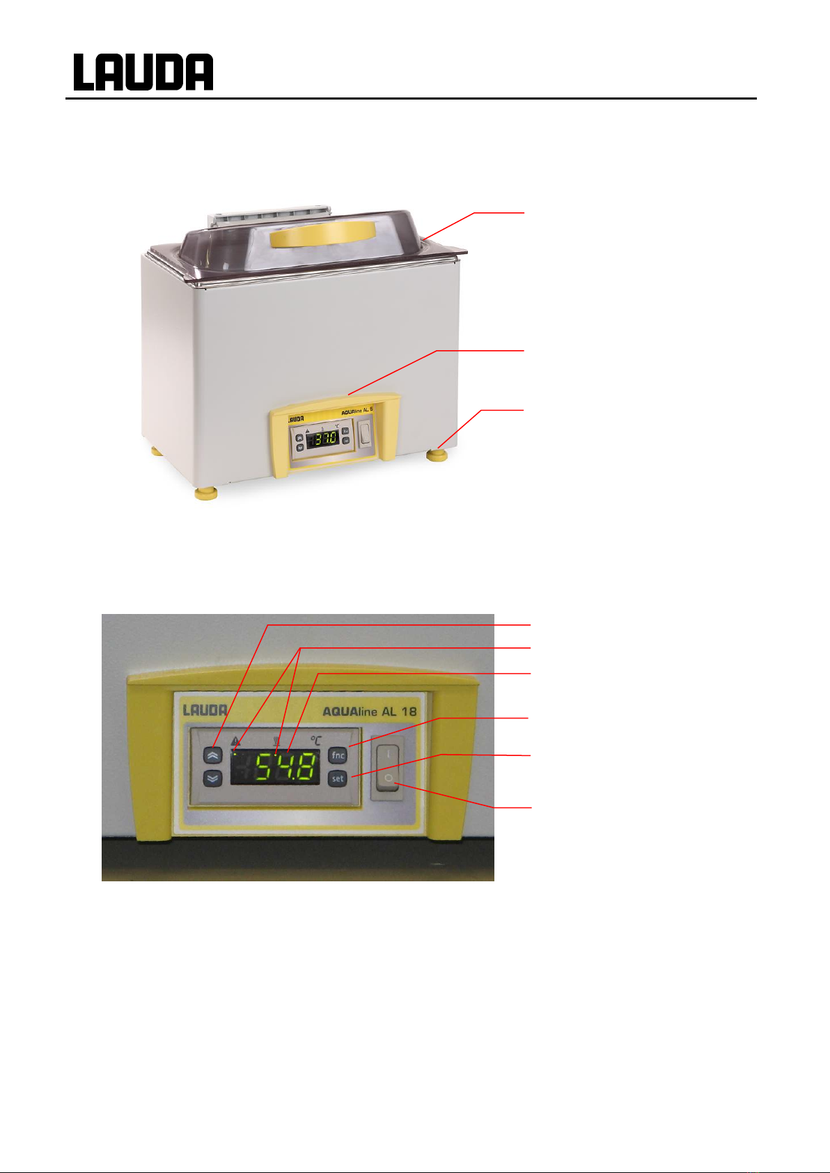
3CONTROL AND FUNCTIONAL ELEMENTS.............................................................................................10
4UNIT DESCRIPTION...................................................................................................................................12
4.1 ENVIRONMENTAL CONDITIONS.................................................................................................................12
4.2 DEVICE TYPES........................................................................................................................................12
4.3 MATERIAL ..............................................................................................................................................12
4.4 TEMPERATURE DISPLAY,CONTROLLER AND SAFETY CIRCUIT.....................................................................12
5UNPACKING...............................................................................................................................................13
6PREPARATIONS........................................................................................................................................14
6.1 ASSEMBLY AND SITING............................................................................................................................14
6.2 FILLING AND EMPTYING ...........................................................................................................................15
6.3 HEAT TRANSFER LIQUIDS ........................................................................................................................16
7OPERATION ...............................................................................................................................................17
7.1 MAINS CONNECTION ...............................................................................................................................17
7.2 SWITCHING ON .......................................................................................................................................17
7.3 TEMPERATURE SET-POINT SETTING .........................................................................................................18
7.4 CONTROLLER ERROR SIGNALS.................................................................................................................18
8MAINTENANCE..........................................................................................................................................19
8.1 LOW LEVEL PROTECTION.........................................................................................................................19
8.2 UNLOCK THE SAFETY TEMPERATURE LIMITER ...........................................................................................19
8.3 CLEANING ..............................................................................................................................................19
8.4 MAINTENANCE AND REPAIR .....................................................................................................................20
8.5 DISPOSAL OF THE PACKAGING.................................................................................................................21
8.6 ORDERING SPARES AND NAME PLATE.......................................................................................................21
9ACCESSORIES ..........................................................................................................................................22
10 TECHNICAL DATA.....................................................................................................................................23
CONFIRMATION
Explanation of signs
Danger:
This sign is used where there may be injury to person-
nel if a recommendation is not followed accurately or is
disregarded.
Note:
Here special attention is drawn to some aspect. May
include reference to danger.
Reference:
Refers to other information in different sections.

Aqualine
15.03.18/ YACE0086 Safety notes 7
1 Safety notes
1.1 General safety notes
A water bath is intended for heating water according to the needs of the user. This leads to hazards by
high temperatures, fire, and the general hazards by the use of electrical energy.
The user is largely protected through the application of the appropriate standard specifications.
Additional hazards may arise from the type of material being thermostated, e.g. when going above or
below certain temperature levels or through breaking of the container and reaction with the heat carrier
liquid (water).
It is not possible to cover all possibilities; they remain largely within the responsibility and the judgement
of the user.
The unit must only be used as intended and as described in these Operating Instructions. This includes
operation by suitably instructed qualified personnel.
The units are not designed for use under medical conditions according to DIN EN 60601-1 or IEC 601-1!
Classification in accordance with EMC requirements
Device
Immunity
Emissions Class
Customer power supply
Aqualine water baths
Type 2 in accordance
with
DIN EN 61326-1
Emissions Class B
in accordance with
CISPR 11
Worldwide
No limitation
Instructions for Class A digital devices, USA:
“This equipment has been tested and found to comply with the limits for Class A digital device, pursuant
to Part 15 of the FCC (Federal Communication Commission) Rules. These limits are designed to provide
reasonable protection against harmful interference when the equipment is operated in a commercial en-
vironment. This equipment generates, uses, and can radiate radio frequency energy and, if not installed
and used in accordance with the instruction manual, may cause harmful interference to radio communi-
cations. Operation of this equipment in a residential area is likely to cause harmful interference in which
case the user will be required to correct the interference at his own expense.”
“This device complies with Part 15 of the FCC (Federal Communication Commission) Rules. Operation
is subject to the following two conditions: (1) This device may not cause harmful interference, and (2) this
device must accept any interference received, including interference that may cause undesired opera-
tion.”
Instructions for Class A digital devices, Canada:
“This Class A digital apparatus complies with Canadian ICES-003” (ICES = Interference Causing
Equipment Standards).
« Cet appareil numérique de la Classe A est conforme à la norme NMB-003 du Canada ».

Aqualine
8Safety notes 15.03.18/ YACE0086
1.2 Other safety notes
The units are designed for operation with non-flammable liquids to DIN EN 61010-2-010.
Check the device carefully for shipping damage before putting into operation. Never operate the de-
vice if you have found shipping damage.
Connect the unit to a grounded mains power socket.
Parts of the bath cover may reach surface temperatures above 70 °C when operating at higher tem-
peratures. Take care when touching it!
Always pull out the mains plug before cleaning, maintenance or moving the water bath!
Only have specialists carry out repairs requiring the opening of the housing.
Values for temperature control and indicating accuracy apply under normal conditions according to
DIN 12876. High-frequency electromagnetic fields may under special conditions lead to unfavourable
values. This does not affect the safety.

Aqualine
15.03.18/ YACE0086 Brief operating instructions 9
2 Brief operating instructions
This brief instruction shall give you the possibility to operate the unit quickly. For safe oper-
ation of the unit it is absolutely necessary to read carefully all the instructions and safety
notes!
1. Assemble unit and add items as appropriate (6).
2. Fill the unit with decalcified water (6.3). Take care of the level of the bath liquid! (6.2).
The units are designed for operation with non-flammable liquids to DIN EN 61010-2-010.
3. Connect the unit only to a socket with a protective earth (PE) connection.
Compare the information on the rating label with the supply details.
4. Switch on at the mains switch .
5. The controller runs a self-test after switching on. For a few seconds all segments are flashing.
6. Setting the set point temperature
First the current bath temperature is displayed.
Press the key shortly. The display shows
SEt. Press shortly again the set point
will be displayed.
Adjust the set-point using the keys
or .
After 30 seconds without entry the current bath
temperature will be displayed again.
Save the set value with twice or wait for
30 s till the set point value will be saved
automatically.
2§1
°C
!
fnc
set

Aqualine
10 Control and functional elements 15.03.18/ YACE0086
3 Control and functional elements
1. Gable cover made of plastic material, swiveling and demountable
2. Temperature controller with LED display
3. Mounting feet
4. Control keys
5. Status LED K1 and K2
6. LED display
7. Save key
8. Key for set point settings
9. Mains switch
4.
8.
1.
3.
2.
6.
5.
7.
9.

Aqualine
12 Unit description 15.03.18/ YACE0086
4 Unit description
4.1 Environmental conditions
The operation of the thermostats is only allowed under the following conditions as specified in
DIN EN 61010-2-010:2003 and DIN EN 61010-1:2001:
Indoor use.
Operation up to a height of 2000 m above sea level is admissible.
Foundation must be dense, even, non-slippery and non-flammable.
Ambient temperature range (10).
Use only within this range for an undisturbed operation.
Mains supply voltage fluctuations (10).
Maximum relative humidity (10).
Transient over voltage according to Installation Categories (Over voltage Categories) II.
Pollution degree: 1.
4.2 Device types
The type designation of the Aqualine water baths is composed of the abbreviation "AL" for Aqualine and
the bath volume.
Example: Aqualine bath with 12 liters maximum volume gives LAUDA AL 12.
All water baths are supplied as standard with a fitted bath cover.
4.3 Material
The bath vessel is made of rust-free stainless steel. The gable cover is made of transparent plastic ma-
terial (Polycarbonate).
The bath cover made of steel is not interchangeable against the bath cover made of plastic material.
4.4 Temperature display, controller and safety circuit
The bath tank is heated from underneath.
The acquisition of the actual value and the control of the bath temperature are carried out with a temper-
ature sensor fitted to the underside of the bath tank.
The units are fitted with a 3-figure 7-segment LED display for indicating the bath temperature and set-
tings as well as the operating status. Entry of the set-point value occurs using adjust keys.
All settings are saved even with a mains failure or with the mains switch set to "OFF".
If the water level in the bath is lower than approx. 20 mm, a safety temperature limiter system will switch
off the heater. The LED display goes out. Unlocking the protection system (8.1).
If the water bath is operated without water and the temperature on the bottom of the tank reaches
110 °C, an acoustic alarm sounds and the LED display indicates: E1.
Resetting the alarm (7.4).
If the water bath is operated without water and the temperature on the bottom of the tank reaches
150 °C, a safety temperature limiter system switches the device off.
Unlocking the limiter system (8.2).

Aqualine
15.03.18/ YACE0086 Unpacking 13
5 Unpacking
After unpacking, first check the unit and accessories for any transport damage. If contrary to expectations
the unit is found to be damaged, the shipping company or supplier must be immediately informed so that
verification can take place.
Please inform also the LAUDA Service for Constant Temperature Equipment (8.6).
Standard accessories:
Article number
Quantity
Designation
HGH 194
1
Bath gable cover made of
transparent plastic material
(Polycarbonate) (fitted)
for every Aqualine water baths AL 2
and AL 5
HGH 195
1
Bath gable cover made of
transparent plastic material
(Polycarbonate) (fitted)
for Aqualine water bath AL 12
HGH 196
1
Bath gable cover made of
transparent plastic material
(Polycarbonate) (fitted)
for every Aqualine water baths AL 18
and AL 25
EZB 260
1
Warning label
for all Aqualine water baths
EZ 266
1
Hand pump
for Aqualine water baths AL 12, AL 18
and AL 25 only
YACE0086
1
Operating instructions
for all Aqualine water baths

Aqualine
14 Preparations 15.03.18/ YACE0086
6 Preparations
6.1 Assembly and siting
Place the unit on a horizontal and flat sur-
face.
Do not cover the ventilation opening on
the bottom of the unit and the heatsink at
the back of the unit. Keep a clear distance
of at least 20 cm.
The gable cover has two positions:
Closed or opened.
In the position shown (see figure left side),
the gable cover can be removed.
At bath temperature above 70 °C the label supplied must be affixed on the
bath in a clearly visible position.

Aqualine
15.03.18/ YACE0086 Preparations 15
6.2 Filling and emptying
Filling
Maximum level 20 mm below the top edge of the bath.
Operation down to round about 30 mm minimum level is
possible.
Emptying
Switch off the water bath and withdraw the mains plug.
Empty the bath with the aid of a suction pump or other
extracting device.
Siphon Hand Pump
LAUDA catalogue number EZ 266
The units are designed for operation with non-flammable liquids to
DIN EN 61010-2-010.
Do not drain the heat transfer liquid (water) in hot conditions!

Aqualine
16 Preparations 15.03.18/ YACE0086
6.3 Heat transfer liquids
LAUDA
designation
Working
temperature
range
Chemical
designation
Viscosity
(kin)
Viscosity
(kin) at
temperature
Size
Catalogue number
from °C
to °C
mm²/s
at 20°C
mm²/s
5 L
10 L
20 L
Aqua 90
5...90
decalcified
water with
water stabi-
liser
1
--
LZB 120
LZB 220
LZB 320
IMPORTANT There are different sorts of water!
Tap water may be unsuitable for operation due to the calcium carbonate content risk of
calcification of the stainless steel tank.
High purity water (from ion exchangers) and distilled or bidistilled water are unsuitable for
operation due to the corrosive properties of these media. High purity water and distil-
lates are suitable as a medium after the addition of 0.1 g of soda (Na2CO3, sodium car-
bonate) / liter of water.
TIP: Water baths can be operated ideally with LAUDA Aqua 90, available in container
sizes of 5, 10 or 20 liters (order number LZB 120, LZB 220 or LZB 320).
There is a risk of electrochemical oxidation with the use of racks of non-ferrous metals or
non-ferrous metal samples.
The LAUDA Aqualine water bath tanks are produced in stainless steel 1.4301 and are
accordingly resistant to mechanical and chemical stresses.
Due to the different electrochemical potentials of metals electrochemical oxidation may
occur in the case of direct contact between the tank and a rack (e.g. copper) and the bath
may corrode despite the use of the highest quality materials for the tank.
TIP: Avoid the use of this type of rack or the direct contact with this sort of rack or contact
with non-ferrous metal samples and the inside of the container. Use original LAUDA
stainless steel racks and commercially available racks in temperature-resistant plastics.

Aqualine
15.03.18/ YACE0086 Starting up 17
7 Operation
7.1 Mains connection
Compare the rating on the name-plate with the mains voltage.
Connect the unit only to sockets with a protective earth conductor (PE).
No liability is accepted for incorrect mains connections!
Please make sure that your mains plug is equipped with at least the following safety
fuses see (10 Technical Data).
Ensure that the unit is filled in accordance with Section 6.2!
Note for electric installation on site:
The devices must be protected with a 16-ampere circuit breaker fitted during installation.
Exception: Devices with 13 ampere UK plugs.
7.2 Switching on
Switch on using the mains switch. The green LED indica-
tor is illuminated.
The controller runs a self-test after switching on. For a few
seconds all segments are flashing.
First the current bath temperature is displayed.
The values are accepted which were set before the
switch-off.
If an alarm has occurred, the LED 1 is illuminated.
If the heater feeds heat to the bath, at the normal operation, the LED 2 is illuminated.
2§1
°C
!
fnc
set
LED 2
LED 1

Aqualine
18 Starting up 15.03.18/ YACE0086
7.3 Temperature set-point setting
Display and modification of the operating temperature set-point:
Press the key shortly. The display shows
SEt. Press shortly again
the set point will be displayed.
Adjust the set-point using the keys
or .
After 30 seconds without entry the bath tem-
perature will be displayed again.
Save the set value twice with or wait for
30 s till the set point value will be saved
automatically.
The LED 2 is illuminated, if the heater feeds
heat to the bath.
7.4 Controller error signals
LED
display
Visual alarm switch-
off
Device status
Cause
Remedy
E1
Automatic reset when
the signal returns to the
acquisition range.
Heater is OFF.
No or to less water in the
tank.
Topping up with de-
calcified water.
Temperature above
110 °C. Temperature sen-
sor, connecting wires or
controller is defective.
Contact LAUDA Ser-
vice Constant Tem-
perature Equipment.
3/3
°C
!
fnc
set
LED 2

Aqualine
15.03.18/ YACE0086 Maintenance 19
8 Maintenance
8.1 Low level protection
Evaporation may cause a slowly water loss. If
the level is lower than app. 20 mm, a mechan-
ical safety temperature limiter cuts off the
complete voltage supply.
If lack of water was the problem, the limiter
can be deactivated once water has been add-
ed.
To do this, press the button at the rear of the
water bath until a noticeable latching occurs.
8.2 Unlock the safety temperature limiter
Two sensors monitor the temperature on the bottom of the bath.
If the temperature on the bottom of the tank reaches above 110 °C, the LED display indicates: E1.
Immediately switch off the device with the mains switch and rectify cause of fault. Frequently it is a low
water level in the tank (7.4).
Above approx. 150 °C bottom temperature a
mechanical safety temperature limiter cuts off
the complete voltage supply. Thereupon the
LED display goes out.
This protective device is not self-cancelling
according to DIN EN 61010-2-10.
First, the cause of the overtemperature must
be found. If lack of water was the problem, the
limiter can be deactivated once water has
been added.
To do this, press the button at the rear of the
water bath until a noticeable latching occurs.
The safety temperature limiter must not be deactivated when a mechanical or electri-
cal fault is suspected.
If necessary, contact the authorized LAUDA Service agents or the LAUDA Service
Constant Temperature Equipment (8.6).
8.3 Cleaning
Withdraw the equipment mains plug before cleaning!
Cleaning can be carried out with water to which a few drops of surfactant (washing-up liquid), have
been added and using a damp cloth.

Aqualine
20 Maintenance 15.03.18/ YACE0086
Water must not penetrate the control unit!
Carry out appropriate detoxification if dangerous material has been spilled on or in-
side the unit.
Method of cleaning and detoxification are decided by the special knowledge of the
user. In case of doubt please contact the manufacturer.
8.4 Maintenance and repair
Withdraw the equipment mains plug before all service and repair work!
Repair on the control unit must only be carried out by properly qualified personnel!
LAUDA Aqualine water baths are maintenance-free. If the heat carrier liquid becomes dirty it has to be
replaced (6.2).
If a fuse blows (supply indication not alight) fit only fuses as specified.
(2 off T (slow blow) 12.5 A (EES 014); 1 off T (slow blow) 0.2 A (EES 069); Size 6.3 x
32 fuses located in the unit).
Changing the fuses:
Before opening, withdraw the mains plug, pick up the gable cover and empty the bath.
Remove the rubber buffer out of the four feet. Release the screws in the feet and in the bottom
panel with a cross-head screwdriver, loosen the earthing cable and remove the bottom panel.
The fuses are located behind the heat sink at the rear of the unit.
Replace the blown fuse and reassemble the water bath in the reverse sequence.
Printed circuit
board
UL 581
F3; T 0.2 A
(EES 069)
F1; F2,
T12.5 A
(EES 014)
Before sending us the unit, please contact our technical service. (8.6).
If the equipment has to be returned to the factory, please ensure that it is carefully and
properly packed. LAUDA accepts no responsibility for damage due to unsatisfactory
packing.
This manual suits for next models
4
Table of contents
Popular Bathtub manuals by other brands

TR
TR Comfortline II operating manual

Kohler
Kohler VINTAGE K-700 Roughing-In Guide

glass 1989
glass 1989 nubea 190/90 manual

American Standard
American Standard Ellisse Elite 2711E Series installation instructions

American Standard
American Standard CHAMPION 6069LCH Installation and operation manual

Aquatica Digital
Aquatica Digital Harmony Duo Installation & Care Manual

PAA
PAA ECOPLUS owner's manual

Kohler
Kohler K-11195X Installation and user guide

Novellini
Novellini Sense 4 Instructions for installation, use and maintenance manual

MAAX
MAAX 106902 installation instructions

Tassili Supra
Tassili Supra 33001709 instruction manual

Sterling
Sterling Bath/Shower System 61040110 Specifications