manuals.online logo
Brands
  1. Home
  2. •
  3. Brands
  4. •
  5. Launch
  6. •
  7. Accessories
  8. •
  9. Launch LTR-03 User manual

Launch LTR-03 User manual

Safety Instructions
Any maintenance and repair work must be carried out
by trained experts. Failure to do so may result in the
failure of the TPMS sensor. LAUNCH does not
assume any liability in case of faulty or incorrect
installation of the unit.
CAUTION
Do not race with the vehicle on which the LTR-01
RF sensor is mounted, and always keep the
drive speed under 240km/h.
To guarantee optimal performance, the sensors
may only be installed with original valves and
accessories provided by LAUNCH.
Make sure to program the sensors using
LAUNCH-specific TPMS tool prior to
installation.
Do not install programmed TPMS sensors in
damaged wheels.
After installing the TPMS sensor, test the
vehicle’s TPMS following the steps described in
the original manufacturer’s user manual to
confirm proper installation.
When mounting/dismounting the wheel, follow
the operation guideline of wheel changer
manufacturer strictly.
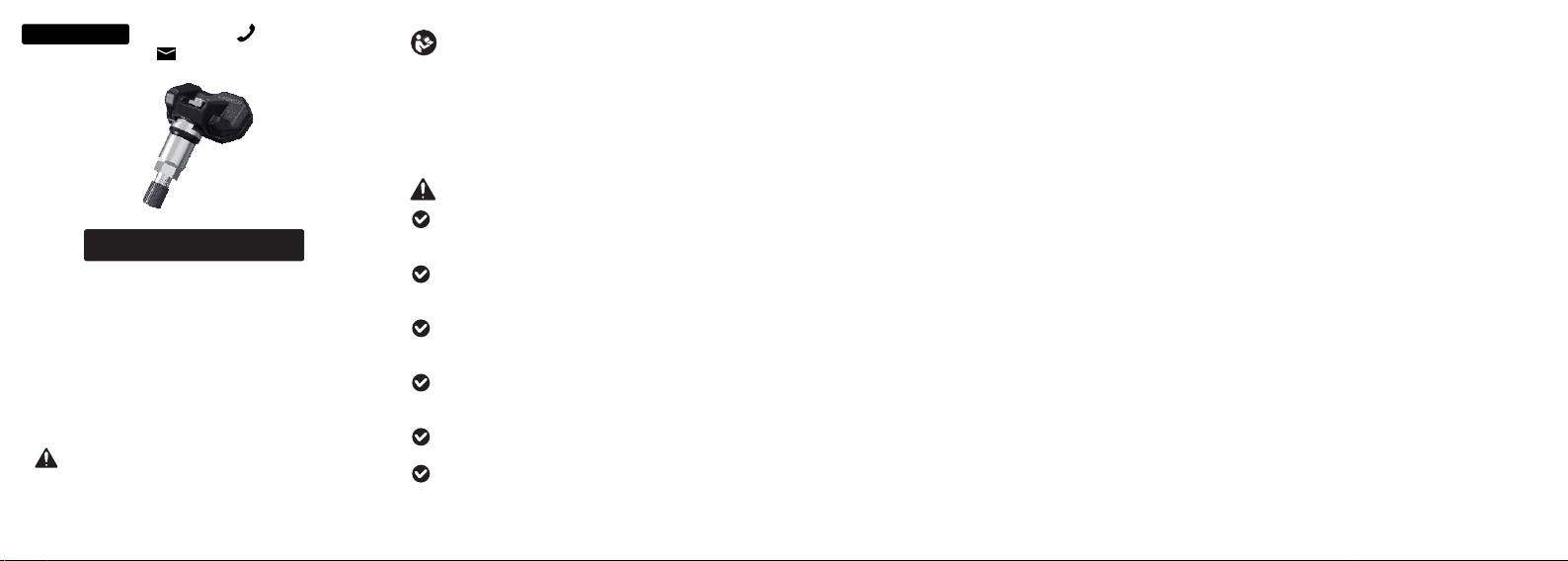
RF-Sensor
QuickStartGuide
LTR-03
IMPORTANT: Read these instructions
carefully and use this unit properly before
operating. Failure to do so may cause damage
and/or personal injury and will void the product
warranty.
www.x431.com
LAUNCH +86-755-84557891
overseas.service@cnlaunch.com
- Increase the separation between the equipment
and receiver.
- Connect the equipment into an outlet on a circuit
different from that to which the receiver is
connected.
FCC Warning
- Reorient or relocate the receiving antenna.
Note: Any changes or modifications not expressly
approved by the party responsible for compliance
could void the user's authority to operate the
equipment. This equipment has been tested and
found to comply with the limits for a Class B digital
device, pursuant to part 15 of the FCC Rules. These
limits are designed to provide reasonable protection
against harmful interference in a residential
installation. This equipment generates uses and can
radiate radio frequency energy and, if not installed
and used in accordance with the instructions, may
cause harmful interference to radio communications.
However, there is no guarantee that interference will
not occur in a particular installation. If this equipment
does cause harmful interference to radio or television
reception, which can be determined by turning the
equipment off and on, the user is encouraged to try to
correct the interference by one or more of the
following measures:
- Consult the dealer or an experienced radio/TV
technician for help.
This device complies with part 15 of the FCC Rules.
Operation is subject to the following two conditions:
(1) This device may not cause harmful interference,
and (2) this device must accept any interference
received, including interference that may cause
undesired operation.
This equipment complies with FCC radiation exposure
limits set forth for an uncontrolled environment.This
equipment should be installed and operated with
minimum distance 20cm between the radiator &your
body.
Disclaimer of Warranties and
Limitation of Liabilities
All information, illustrations, and specifications in this
manual are based on the latest information available at
the time of publication. The right is reserved to make
changes at any time without notice. We shall not be
liable for any direct, special, incidental, indirect
damages or any economic consequential damages
(including the loss of profits) due to the use of the
document.
Warranty
The sensor is guaranteed to be free from material
and manufacturing defects for a period of twenty-four
(24) months or for 31000 miles, whichever comes
first. This warranty covers any defects in materials or
workmanship under normal use during the warranty
period. Excluded from the warranty are defects due
to improper installation and usage, induction of
defect by other products, damage due to collision or
tire failure.
Place the tire on the rim, ensure that the valve starts
on the opposite side of the rim from the tire fitting
head. Mount the tire over the rim.
5. Remounting the tire
Caution: Strictly follow tire changer manufacturer’s
instructions to mount the tire.
Caution: Make sure that the nut and cap are installed
on the outside of the rim.
3. Dismounting the sensor
Remove the cap and nut from
the valve stem, and then
remove the sensor assembly
from the wheel rim.
4. Mounting the sensor and valve
Step 1. Remove the cap and
nut from the valve stem.
Step 2. Place the valve stem through the valve hole of
the rim, ensuring the sensor body located on the
inside of the rim. Assemble the nut back on the valve
stem with a torque of 4N·m, then tighten the cap.
TWC-4 11NIC
Caution: The bead loosener must be facing the
valve.
InstallationSteps
Use the bead loosener to break the tire bead.
1. Loosening the tire
Remove the valve cap and nut and deflate the tire.
2. Dismounting the tire
Clamp the tire on the tire
changer, and adjust the valve
at 1 o’clock to the tire fitting
head. Use the tire tool to
dismount the tire bead.
Caution: Always observe
this starting point during the
whole dismounting process.
Sensor body
Washer&nut
Valvestem
Rubbergrommet
andvalvecore
assembly
Screw
Cap
Weight <30g
Technical Parameters
Dimension(L*W*H) About 72*51*27mm
Working Voltage 3V
IP Rating IP67
Components&Controls
When replacing or servicing the sensor, please only
use the original valves and accessories provided by
LAUNCH to ensure proper sealing. It is mandatory to
replace the sensor if it is externally damage. Always
remember to tighten the nut to the correct torque of 4N·m.
纵向 对折
首页
对折 后最 终尺 寸为 :70mmx50mm
制作要求:
原始文件尺寸为:210mmx100mm
制作方式:横向风琴折,折后尺寸为:
70mmx100mm,然后纵向对折,最终成
品尺寸为70mmx50mm
印刷要求:黑白印刷,采用80g书写纸

Popular Accessories manuals by other brands

Bavarian Edge M17471 manual

Bavarian Edge

Bavarian Edge M17471 manual

CMA Dishmachines RELATIVE HUMIDITY SENSOR BT72i user guide

CMA Dishmachines

CMA Dishmachines RELATIVE HUMIDITY SENSOR BT72i user guide

Mesalabs ViewPoint Professional Series user manual

Mesalabs

Mesalabs ViewPoint Professional Series user manual

Gigaset N300IP user guide

Gigaset

Gigaset N300IP user guide

Pepperl+Fuchs SU17 Series manual

Pepperl+Fuchs

Pepperl+Fuchs SU17 Series manual

SA Sport 5141 Assembly & care instructions

SA Sport

SA Sport 5141 Assembly & care instructions

MUSON Smile Key manual

MUSON

MUSON Smile Key manual

Durr Dental HD 410 Installation and operating instructions

Durr Dental

Durr Dental HD 410 Installation and operating instructions

NeuLog NUL-209 Guide

NeuLog

NeuLog NUL-209 Guide

Heat Controller Flow Controllers Installation, operation & maintenance manual

Heat Controller

Heat Controller Flow Controllers Installation, operation & maintenance manual

EVM EnCore User instructions

EVM

EVM EnCore User instructions

InnoGear Aroma Diffuser user manual

InnoGear

InnoGear Aroma Diffuser user manual

Graco 24K632 Kit instructions

Graco

Graco 24K632 Kit instructions

Oracura OC010 user manual

Oracura

Oracura OC010 user manual

Browan TBAM100-915 Reference manual

Browan

Browan TBAM100-915 Reference manual

ekwb EK-FC1080 GTX TF6 installation manual

ekwb

ekwb EK-FC1080 GTX TF6 installation manual

Banner L-GAGE LE250 IO-Link quick start guide

Banner

Banner L-GAGE LE250 IO-Link quick start guide

Scentuals Motivate user manual

Scentuals

Scentuals Motivate user manual

manuals.online logo
manuals.online logoBrands
  • About & Mission
  • Contact us
  • Privacy Policy
  • Terms and Conditions

Copyright 2025 Manuals.Online. All Rights Reserved.