Mesalabs ViewPoint Professional Series User manual


VPx Sensor User Manual 2
Mesa Labs, Inc.
12100 W. 6th Avenue
Lakewood, CO 80228 USA
Tel: 303-565-2724
monitoring.mesalabs.com
techsupport@mesalabs.com
Contents
1.0 Figures............................................................................................................................................... 3
2.0 Introduction ...................................................................................................................................... 4
2.1 FCC NOTICE ................................................................................................................................... 5
2.2 Industry Canada ............................................................................................................................ 6
3.0 Features ............................................................................................................................................ 7
3.1 Buttons.......................................................................................................................................... 7
3.2 Audio Visual Alarm........................................................................................................................ 7
3.3 Input Types.................................................................................................................................... 8
4.0 Menus ............................................................................................................................................... 9
4.1 Home............................................................................................................................................. 9
4.2 Min Max ........................................................................................................................................ 9
4.3 Clear Min Max............................................................................................................................. 10
4.4 Diagnostics Menu........................................................................................................................ 10
5.0 New Battery ....................................................................................................................................12
5.1 Battery Replacement ..................................................................................................................12
6.0 Ports ................................................................................................................................................ 14
7.0 Specs ............................................................................................................................................... 15
7.1 RTD.............................................................................................................................................. 15
7.2 Temperature and Humidity ........................................................................................................ 15
7.3 Power .......................................................................................................................................... 15
8.0 LCD Icon Legend.............................................................................................................................. 16
9.0 Operation Compatibility .................................................................................................................18
9.1 DS-VP-PRO-900-S Radio Network Compatibility......................................................................... 18
9.1.1 ViewPoint G5 Compatibility ................................................................................................ 18
9.1.2 CheckPoint G4 Compatibility ..............................................................................................18
10.0 Accessory and Probe List ................................................................................................................ 19
11.0 VPx Sensor Models.......................................................................................................................... 19

VPx Sensor User Manual 3
Mesa Labs, Inc.
12100 W. 6th Avenue
Lakewood, CO 80228 USA
Tel: 303-565-2724
monitoring.mesalabs.com
techsupport@mesalabs.com
1.0 Figures
3-1 VPx Sensor with LCD ............................................................................................................................... 7
3-2 VPx Sensor with LCD Buttons.................................................................................................................. 7
Table 3-1 Input Types.................................................................................................................................... 8
4-1 Home Screen........................................................................................................................................... 9
Table 4-1 Access Min Max Menu Procedure ................................................................................................ 9
4-2 Min Max Screen .................................................................................................................................... 10
Table 4-2 Clear Min Max Procedure ........................................................................................................... 10
Table 4-3 Access Diagnostics Screen Procedure.........................................................................................10
4-3 900 MHz Diagnostics Screen.................................................................................................................11
4-4 Wi-Fi Diagnostics Screen.......................................................................................................................11
5-1 VPx Sensor Top and Back View............................................................................................................. 12
5-2 VPx Sensor Internal View (Back Cover Removed) ................................................................................ 13
Table 5-1 Reset Battery Level Display Procedure (LCD).............................................................................. 13
6-0 VPx Sensor Bottom Side View Showing Ports....................................................................................... 14
Table 6-1 VPx Sensor Bottom Side View Showing Ports............................................................................. 14
Table 6-2 VPx Sensor RTD Probe Pin Assignments .....................................................................................14
Table 6-3 VPx Sensor 4-20 ma, 5v, 10v and 30v Inputs ..............................................................................15
Table 8-1 LCD Icon Legend..........................................................................................................................17
Table 9-1 Input and Accessory Type Part Numbers....................................................................................19
Table 10-1 VPx Models ............................................................................................................................... 19

VPx Sensor User Manual 4
Mesa Labs, Inc.
12100 W. 6th Avenue
Lakewood, CO 80228 USA
Tel: 303-565-2724
monitoring.mesalabs.com
techsupport@mesalabs.com
2.0 Introduction
The VPx sensor integrates with Mesa’s ViewPoint 1.1 or above software solution. The VPx 900 MHz
sensor operates in a 902 to 928 MHz range.
This device complies with Part 15 of the FCC Rules. Sensor operation is subject to the following two
conditions: (1) this device may not cause harmful interference, and (2) this device must accept any
interference received, including interference that may cause undesired operation.
Ex.
Warning: This unit is not explosion proof and is not rated for intrinsically safe installations.

VPx Sensor User Manual 5
Mesa Labs, Inc.
12100 W. 6th Avenue
Lakewood, CO 80228 USA
Tel: 303-565-2724
monitoring.mesalabs.com
techsupport@mesalabs.com
2.1 FCC NOTICE
WARNING
This equipment has been tested and found to comply with the limits for a class B digital device, pursuant
to part 15 of the FCC Rules. These limits are designed to provide reasonable protection against harmful
interference in a residential installation. This equipment generates, uses and can radiate radio frequency
energy and if not installed and used in accordance with the instructions, may cause harmful interference
to radio communications. However, there is no guarantee that interference will not occur in a particular
installation. If this equipment does cause harmful interference to radio or television reception, which can
be determined by turning the equipment off and on, the user is encouraged to try to correct the
interference by one or more of the following measures:
* Reorient or relocate the receiving antenna.
* Increase the separation between the equipment and receiver.
* Connect the equipment into an outlet on a circuit different from that to which the receiver is connected.
* Consult the dealer or an experienced radio/TV technician for help.
In order to maintain compliance with FCC regulations, shielded cables must be used with this equipment.
Operation with non-approved equipment or unshielded cables is likely to result in interference to radio
and TV reception. The user is cautioned that changes and modifications made to the equipment without
the approval of manufacturer could void the user's authority to operate this equipment.
RF Exposure Notice: To satisfy RF exposure requirements, this device and its antennas must operate with
a separation distance of at least 20 cm from all persons and must not be co-located or operating in
conjunction with any other antenna or transmitter.

VPx Sensor User Manual 6
Mesa Labs, Inc.
12100 W. 6th Avenue
Lakewood, CO 80228 USA
Tel: 303-565-2724
monitoring.mesalabs.com
techsupport@mesalabs.com
2.2 Industry Canada
This device contains licence-exempt transmitter(s)/receiver(s) that comply with Innovation, Science and
Economic Development Canada’s licence-exempt RSS(s). Operation is subject to the following two
conditions: (1) This device may not cause interference. (2) This device must accept any interference,
including interference that may cause undesired operation of the device.
Le présent appareil est conforme aux CNR d’Industrie Canada applicables aux appareils radio exempts de
licence. L’exploitation est autorisée aux deux conditions suivantes: (1) l’appareil ne doit pas produire de
brouillage, et (2) l’utilisateur de l’appareil doit accepter tout brouillage radioélectrique subi, même si le
brouillage est susceptible d’en compromettre le fonctionnement.

VPx Sensor User Manual 7
Mesa Labs, Inc.
12100 W. 6th Avenue
Lakewood, CO 80228 USA
Tel: 303-565-2724
monitoring.mesalabs.com
techsupport@mesalabs.com
3.0 Features
3.1 Buttons
3-1 VPx Sensor with LCD
Cycle
Used for cycling through screens or menu options
Select
Select menu option
Previous /
Next
Return to previous screen or Next option
Mute
Mute local Audio Visual Alarms
3-2 VPx Sensor with LCD Buttons
3.2 Audio Visual Alarm
VPx Sensor has local Audible Visual alarms to notify individuals of sensor alarm states even with no
access to the Viewpoint software.

VPx Sensor User Manual 8
Mesa Labs, Inc.
12100 W. 6th Avenue
Lakewood, CO 80228 USA
Tel: 303-565-2724
monitoring.mesalabs.com
techsupport@mesalabs.com
LED for Visual Alarm
To mute local Audible and/or visual alarms, press the button to silence the local alarm ONLY.* To
perform corrective action for alarm states, do so in the ViewPoint software.
*Note: This is only possible when the sensor is in an alarm state. It cannot be used to mute future
alarms.
Muting the sensor with the button on the device will only mute that alarm. If, after muting the
local alarm, the sensor comes back into and then goes back out of range again, then the local alarm will
be triggered again and will need to be muted again if desired.
3.3 Input Types
Parameter
Application
Temperature
-200 °C to + 250 °C (Type K thermocouple, up to +538 °C)
Humidity
0% to 100% (Temp 5 °C to +40 °C)
CO2
0% to 20%
O2
0% to 25% (use 4-20 mA sensor and third-party sensor)
Door Status
Open / Closed Door
Horizontal Motion
Platelet Incubator
Dry Contact
Normal v. Alarm State (Normally Closed or Open)
Power
100 to 240 V (Detect Power Outages)
DC Voltage
0 to 5 V, 0 to 10 V, 0 to 20 V, 0 to 30 V
4-20 mA
Various sensors with powered 4-20 mA interface
Differential Pressure
-1.0 to + 1.0 inches H20 /-.25 to +.25 / -.5 to +.5
Particle Count
Utilizes 4-20 mA Sensor Output
Leak Detection
Detect water in critical areas
Table 3-1 Input Types

VPx Sensor User Manual 9
Mesa Labs, Inc.
12100 W. 6th Avenue
Lakewood, CO 80228 USA
Tel: 303-565-2724
monitoring.mesalabs.com
techsupport@mesalabs.com
4.0 Menus
4.1 Home
4-1 Home Screen
4.2 Min Max
To get to the Min-Max screen, start at the Home screen,
Press
Result
Step 1
x1
Min Max Screen
Table 4-1 Access Min Max Menu Procedure

VPx Sensor User Manual 10
Mesa Labs, Inc.
12100 W. 6th Avenue
Lakewood, CO 80228 USA
Tel: 303-565-2724
monitoring.mesalabs.com
techsupport@mesalabs.com
4-2 Min Max Screen
4.3 Clear Min Max
Press
Result
Step 1
x2
Option Screen
Step 2
x1
Select Clear Min Max
Step 3
x1
Confirm Clear Min Max
Table 4-2 Clear Min Max Procedure
4.4 Diagnostics Menu
The VPx sensor has onboard diagnostic capabilities that can assist in a variety of setup or
troubleshooting scenarios.
To access the “Diagnostics” screen, start at the Home screen:
Press
Result
Step 1
x2
Option Screen
Step 2
x1
Move up to “Diagnostics”
Step 3
x1
Diagnostics Screen
Table 4-3 Access Diagnostics Screen Procedure


VPx Sensor User Manual 12
Mesa Labs, Inc.
12100 W. 6th Avenue
Lakewood, CO 80228 USA
Tel: 303-565-2724
monitoring.mesalabs.com
techsupport@mesalabs.com
5.0 New Battery
Note: Use only 3 3.6 V Lithium-Ion Batteries (P/N 166112).
5.1 Battery Replacement
To replace the (3) 3.6V lithium batteries in the VPx sensor, press down on the two recessed areas on the
rear plate of the sensor and pull back the back cover to open the unit.
5-1 VPx Sensor Top and Back View

VPx Sensor User Manual 13
Mesa Labs, Inc.
12100 W. 6th Avenue
Lakewood, CO 80228 USA
Tel: 303-565-2724
monitoring.mesalabs.com
techsupport@mesalabs.com
5-2 VPx Sensor Internal View (Back Cover Removed)
After replacing the batteries, it is necessary to reset the battery level indicator. To reset the battery level
indicator, start from the Home screen:
Press
Result
Step 1
x2
Option Screen
Step 2
x2
Move up to “New Battery”
Step 3
x1
New Battery Confirmation
Step 4
x1
“Confirm” New Battery
Table 5-1 Reset Battery Level Display Procedure (LCD)
VPx Sensor User Manual 14
Mesa Labs, Inc.
12100 W. 6th Avenue
Lakewood, CO 80228 USA
Tel: 303-565-2724
monitoring.mesalabs.com
techsupport@mesalabs.com
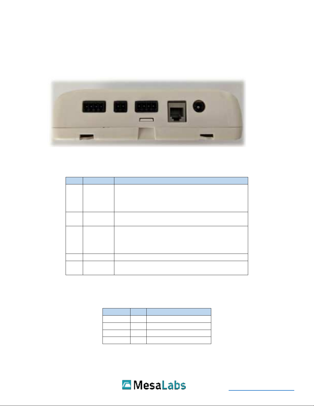
6.0 Ports
The VPx Sensor has 4 I/O ports that can accept 2 channels of RTD temperature probes, 2 channels of
general-purpose analog probes: 4-20 ma, 5v, 10v, 20v and 30v, a discrete switch/contact input, and one
I2C input for a Humidity/Temperature probe.
6-0 VPx Sensor Bottom Side View Showing Ports
VPx Sensor Ports Defined:
Port
Channel
Description
1
1
4-Wire RTD
4-Wire Cryo RTD
DC Voltage - 0 to 5 V, 0 to 10 V, 0 to 20 V, 0 to 30 V
DC 4-20 ma - Various sensors
2
Discrete
Door Status - Open / Closed Door
Dry Contact - Normally Closed or Open
3
2
4-Wire RTD
4-Wire Cryo RTD
DC Voltage - 0 to 5 V, 0 to 10 V, 0 to 20 V, 0 to 30 V
DC 4-20 ma - Various sensors
4
1 and/or 2
Humidity/Temperature
5
N/A
External Power - 5V 1A AC/DC Wall Mount Adapter
(TWA22 –Power Supply)
Table 6-1 VPx Sensor Bottom Side View Showing Ports
Connections for RTD Probes:
Channel
Pin
Description
1 & 2
1
RTD –black wire
2
RTD –black wire
3
RTD –white wire
4
RTD –white wire
Table 6-2 VPx Sensor RTD Probe Pin Assignments
12345

VPx Sensor User Manual 15
Mesa Labs, Inc.
12100 W. 6th Avenue
Lakewood, CO 80228 USA
Tel: 303-565-2724
monitoring.mesalabs.com
techsupport@mesalabs.com
Connections for 4-20 ma, 5v, 10v and 30v Inputs:
Channel
Pin
Description
1 & 2
1
Not connected
2
4-20 ma in; 5,10,20,30v in
3
Ground
4
Not connected
Table 6-3 VPx Sensor 4-20 ma, 5v, 10v and 30v Inputs
7.0 Specs
All specs below are estimated ranges for the particular inputs. Please refer to the probe specific
documentation for the exact ranges and tolerances.
7.1 RTD
The VPx sensor utilizes (2) 1,000 Ohm RTDs to cover -200°C to +140°C
4-Wire RTD –(P/N CM-000188)
Range: -90°C to +140°C
Tolerance: ±0.5°C @ -25°C to +45°C (±1.0°C @ -90°C to -26°C and +46°C to +140°C)
4-Wire Cryo RTD –(P/N CM-000189)
Range: -200°C to +70°C
Tolerance: ±1.0°C over full operating range
7.2 Temperature and Humidity
VPx monitors temperature and humidity with an external probe.
Temperature and Humidity Probe –(P/N 72112)
Range: +5°C to 40°C and 10% RH to 90% RH
Accuracy: ±0.5°C and ±3% RH
7.3 Power
VPx sensor makes use of a 5V 1A AC/DC Wall Mount Adapter (TWA22 –Power Supply)

VPx Sensor User Manual 16
Mesa Labs, Inc.
12100 W. 6th Avenue
Lakewood, CO 80228 USA
Tel: 303-565-2724
monitoring.mesalabs.com
techsupport@mesalabs.com
8.0 LCD Icon Legend
Icon
Description
Alarm, above/below alarm limits
Alarm, limits (Min-Max screen)
Battery Full
Battery 2/3
Battery 1/3
Battery Low
A/C Power connected
Home
Settings
Link broken
Link connected
Min Max
Fast Transmit
Memory 1/3 full
Memory 2/3 full
Memory full

VPx Sensor User Manual 17
Mesa Labs, Inc.
12100 W. 6th Avenue
Lakewood, CO 80228 USA
Tel: 303-565-2724
monitoring.mesalabs.com
techsupport@mesalabs.com
Sound On
Sound Muted
Icon for Min/Max screen
Motion (not moving)
Motion (Moving)
Contact
No Contact
Door Open
Door Closed
Signal Quality (no signal)
Signal Quality –Poor
Signal Quality –Fair
Signal Quality –Good
Signal Quality –Best
Table 8-1 LCD Icon Legend

VPx Sensor User Manual 18
Mesa Labs, Inc.
12100 W. 6th Avenue
Lakewood, CO 80228 USA
Tel: 303-565-2724
monitoring.mesalabs.com
techsupport@mesalabs.com
9.0 Operation Compatibility
9.1 DS-VP-PRO-900-S Radio Network Compatibility
The DS-VP-PRO-900-S supports two radio networks: “ViewPoint G5 Compatibility” and “CheckPoint G4
Compatibility”. The sensor can be configured for either mode using the VPx Configuration Utility. To
use the utility to set the mode, first click the “Read All” button, navigate to the Wi / Radio tab and select
an option in the “Compatibility Mode” field.
Click the “Apply Radio + Flexband Config” button.
9.1.1 ViewPoint G5 Compatibility
Select “ViewPoint G5 Compatibility”mode when using the sensor with a ViewPoint radio network and
when the sensor will be communicating with a ViewPoint AP.
For “ViewPoint G5 Compatibility “ (G5/G6 Mode) (902.62 to 927.62 MHz):
Hop Table
Frequency Range MHz
Main (0)
906.12 to 924.12
Low (1)
902.62 to 914.87
High (2)
914.87 to 927.62
Make sure to select the hop table that the radio network is using. The default hop table used is 0 –
Main. Use the other hop tables in case there is interference issues or to segregate between radio
networks.
9.1.2 CheckPoint G4 Compatibility
Select “CheckPoint G4 Compatibility” mode when using the sensor with a CheckPoint radio network and
when the sensor will be communicating with a CheckPoint AP.

VPx Sensor User Manual 19
Mesa Labs, Inc.
12100 W. 6th Avenue
Lakewood, CO 80228 USA
Tel: 303-565-2724
monitoring.mesalabs.com
techsupport@mesalabs.com
For “CheckPoint G4 Compatibility “ (G4 Compatibility Mode) (903.000 to 926.000
MHz):
Hop Table
Frequency Range MHz
Num Transmitting
Channels
Standard (0)
906.000 to 924.000
58
Full (1)
903.000 to 926.000
58
Low (2)
903.000 to 913.325
58
High (3)
914.773 to 926.000
58
Make sure to select the hop table that the radio network is using. The default hop table used is 0 –
Standard. Use the other hop tables in case there is interference issues or to segregate between radio
networks.
10.0 Accessory and Probe List
Input/Accessory Type
Part Number
Standard RTD
CM-000188
Cryo RTD
CM-000189
Temp/Humidity (Snap)
72112 (requires CM-000164)
Analog Cable
CM-000284
Door Switch, Motion, Alarm Contact
CM-000183
3.6V Li Batteries
166113
AC Adapter
TWA26
Table 10-1 Input and Accessory Type Part Numbers
11.0 VPx Sensor Models
VPx Sensor Model
Part Number
ViewPoint Professional 900MHz Sensor
DS-VP-PRO-900-S
Table 10-1 VPx Models
This manual suits for next models
3
Table of contents
Other Mesalabs Accessories manuals


Popular Accessories manuals by other brands

Modine Manufacturing
Modine Manufacturing ECO AP 080 Technical manual

Manitowoc
Manitowoc K00179 installation instructions

PCB Piezotronics
PCB Piezotronics 137B29B manual

PSI Woodworking Products
PSI Woodworking Products PKCAPRI instructions

Syrinix
Syrinix PIPEMINDER S product manual

Xantrex
Xantrex ALM - REV A manual


Kutai electronics
Kutai electronics EM81 Quick manual guide

skywalker sports
skywalker sports SWBB1200 user manual

Niles
Niles MSU140 Features & specifications manual

Balluff
Balluff BOS R254K-UUI-LH10-S4 manual

ZipKord
ZipKord ZKPRB31270BK Operator's manual

Pepperl+Fuchs
Pepperl+Fuchs SmartRunner Detector manual