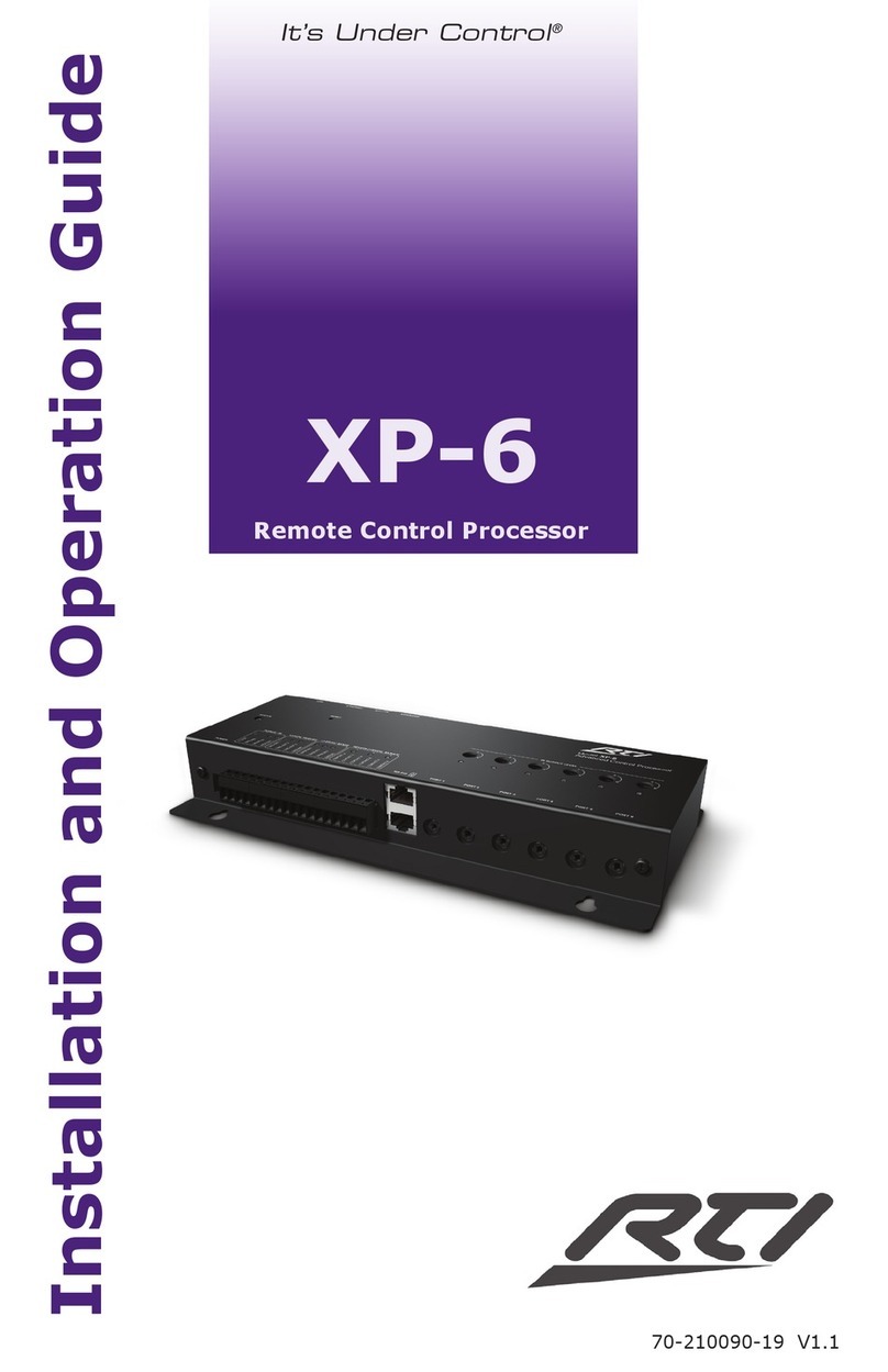
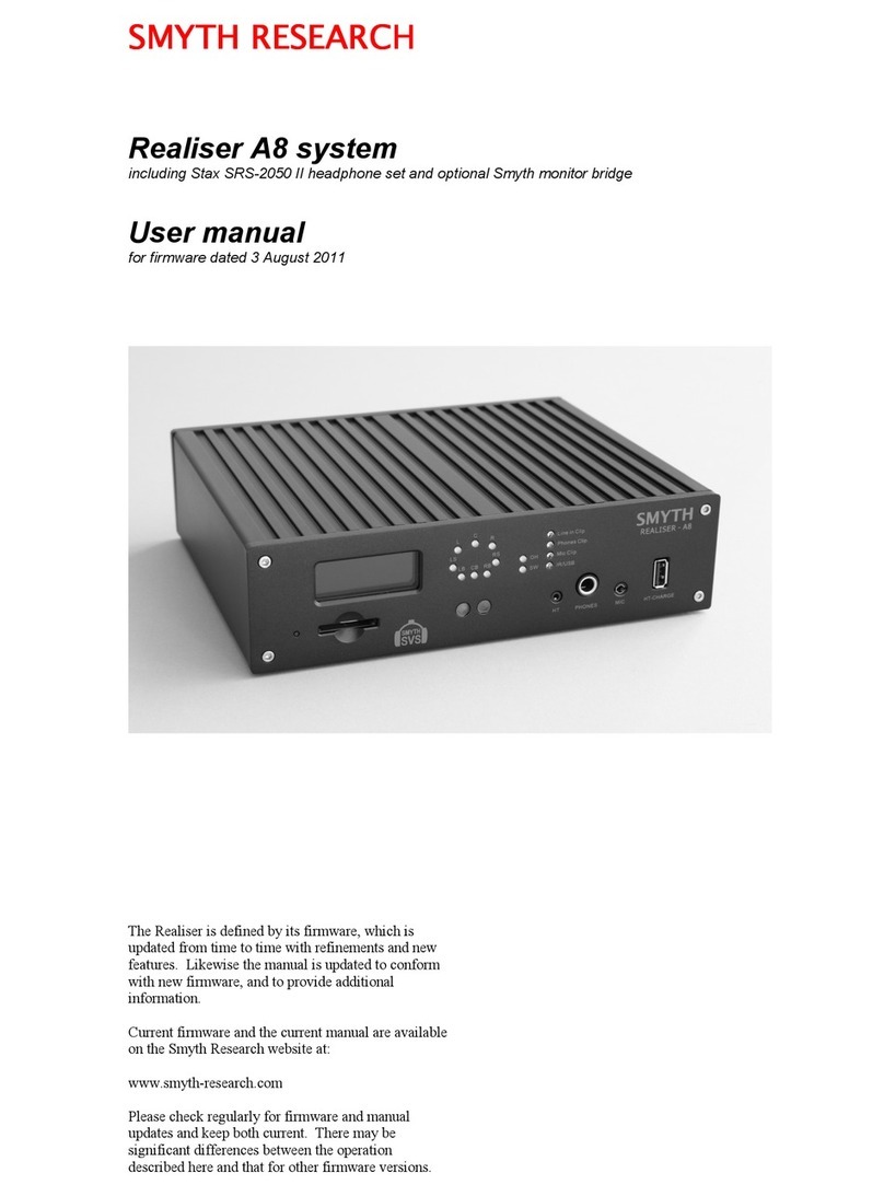
Lavry 3000S User manual

Model 3000S 96kHz
Digital Optimizer
Operations Manual
Lavry Engineering, Inc.
P.O. Box 4602
Rolling Bay, Washington U A
98061
http: //www.lavryengineering.com/
E-Mail: [email protected]
Revision 1.4
ovember 10, 2008


Operations Manual LE3000S
1
LIMITED WARRANTY
Subject to the conditions set forth below, for one year after the original purchase date of the product, Lavry
Engineering will repair the product free of charge in the nited States in the event of a defect in materials or
workmanship.
Lavry Engineering may exchange new or rebuilt parts for defective parts. Please call the factory for an RMA
number prior to shipment. No product will be accepted for warranty service without a pre-issued RMA number.
This warranty is extended only to an original purchaser of the product from Lavry Engineering, or an authorized
reseller of Lavry Engineering. Products that are purchased from unauthorized resellers do not have any warranty
coverage. A valid purchase receipt or other valid proof of purchase will be required before warranty service is
provided. This warranty only covers failures due to defects in materials or workmanship and does not cover
damages which occur in shipment or failures resulting from accident, misuse, line power surges, mishandling,
maintenance, alterations and modifications of the product, or service by an unauthorized service center or
personnel. Lavry Engineering reserves the right to deny warranty service to products that have been used in
rental, service bureau, or similar businesses.
This limited warranty gives you specific legal rights. You may have others which vary from state/jurisdiction to
state/jurisdiction.
LIMITS AND EXCLUSIONS
LAVRY ENGINEERING DOES NOT, BY VIRT E OF THIS AGREEMENT, OR BY ANY CO RSE OF
PERFORMANCE, CO RSE OF DEALING, OR SAGE OF TRADE, MAKE ANY OTHER WARRANTIES,
EXPRESS OR IMPLIED, INCL DING, WITHO T LIMITATION, ANY WARRANTY OF MERCHANTABILITY,
FITNESS FOR A PARTIC LAR P RPOSE, TITLE OR NONINFRINGEMENT, AND ALL S CH WARRANTIES
ARE HEREBY EXPRESSLY DISCLAIMED. LAVRY ENGINEERING EXPRESSLY DISCLAIMS ANY IMPLIED
INDEMNITIES. LAVRY ENGINEERING SHALL NOT BE LIABLE FOR ANY INDIRECT, INCIDENTAL,
CONSEQ ENTIAL, P NITIVE, SPECIAL OR EXEMPLARY LOSSES OR DAMAGES, INCL DING, WITHO T
LIMITATION, DAMAGES TO RECORDINGS, TAPES OR DISKS, DAMAGES FOR LOSS OF B SINESS
PROFITS, B SINESS INTERR PTION, LOSS OF B SINESS INFORMATION, LOSS OF GOODWILL, COVER,
OR OTHER PEC NIARY LOSS, ARISING O T OF OR RELATING TO THE SE OF THE PROD CT, OR
ARISING FROM BREACH OF WARRANTY OR CONTRACT, NEGLIGENCE, OR ANY OTHER LEGAL THEORY,
EVEN IF LAVRY ENGINEERING HAS BEEN ADVISED OF THE POSSIBILITY OF S CH LOSSES OR
DAMAGES. ANY DAMAGES THAT LAVRY ENGINEERING IS REQ IRED TO PAY FOR ANY P RPOSE
WHATSOEVER SHALL NOT EXCEED THE ORIGINAL COST PAID TO LAVRY ENGINEERING FOR THE
APPLICABLE PROD CT. BECA SE SOME STATES/J RISDICTIONS DO NOT ALLOW THE EXCL SION OR
LIMITATION OF LIABILITY FOR CONSEQ ENTIAL OR INCIDENTAL DAMAGES, THE FOREGOING
LIMITATION MAY NOT APPLY TO YO .
Copyright © 2002 by Lavry Engineering, Inc. All rights reserved.
Lavry Engineering ® is a registered trademark of Lavry Engineering, Inc.
Acoustic Bit Correction™ is a registered Trademark of Lavry Engineering, Inc.
email: techsupport@lavryengineering.com
Internet: http://lavryengineering.com/

Operations Manual LE3000S
2
Table of Contents
Limited Warranty ............................................................................................ 1
PART I
Introduction ............................................................................................... 3
Main Screen ................................................................................................... 4
24 High Frequency Sample Rate Conversion ................................................ 5
24 Bit Encode and Decode............................................................................. 5
2:1 Synchronous Downsampling .................................................................... 5
Input Selection Screen ................................................................................... 6
Word Length / Copy Protection / Generation Screen ..................................... 6
Audio Control Screen ..................................................................................... 7
Bar-Graph, Emphasis, and Display Screen.................................................... 7
Options Screen............................................................................................... 8
Acoustic Bit Correction Screen....................................................................... 8
Store Preset Screen ....................................................................................... 9
Signal Analysis Screen................................................................................... 10
Test Tone Screen........................................................................................... 11
Delay Screen.................................................................................................. 11
PART II
Tutorial ...................................................................................................... 12
Connections ................................................................................................... 12
Starting p ..................................................................................................... 12
Input Selection................................................................................................ 12
Monitoring Input Data ..................................................................................... 12
Bar-Graph....................................................................................................... 13
Output Format and Sample Rate Conversion ................................................ 13
Options Screens............................................................................................. 14
Power- p Preset ............................................................................................ 14
Test Tones ..................................................................................................... 14
sing the Tone Generator and THD+N Features........................................... 15
PART III
Specifications............................................................................................ 16
Appendix I
Acoustic Bit Correction™ .......................................................................... 19
Noise-Shaping Curves .............................................................................. 23
Appendix II
Testing Of Asynchronous Sample Rate Converters.................................. 24
Appendix III
Signal Analysis of THD+N......................................................................... 26

Operations Manual LE3000S
3
PART I: Introduction
Operation of the Model 3000S Digital Optimizer requires the use of five push button switches located on
the front panel. The two-line liquid crystal display is organized for quick and intuitive operator interface.
The unit features eleven screen displays.
Push Button Switches:
ENTER Introduces and moves the cursor through screen positions that can be edited by the operator.
CURSOR Push buttons allow the user to choose a screen and to select the cursor
UP/DOWN position. The P/DOWN buttons are also utilized when changing digits of a selected entry.
GO Executes an edited screen.
EXIT Removes the cursor and allows selection of other screens with the P/DOWN buttons.
Pressing EXIT again will cause the unit to go to the main screen.
Scroll Through Screens:
If the screen cursor is present, you need to remove it by pressing EXIT. When the screen cursor is not
present, the UP and DOWN buttons serve to move from screen to screen.
Edit Screens
Press ENTER to introduce the screen cursor at the first editable location. Each additional pressing of
ENTER will move the screen cursor to the next editable location. The settings at an editable location may
be changed by the use of the P/DOWN buttons.
Holding the UP or DOWN button will automatically advance the settings. This feature is particularly useful
for increasing or decreasing numbers (such as test tone frequency, preset number, word length and
amplitude).
The GO button is used to execute an action. Seven screens react to a change of settings immediately,
and pressing GO is not necessary. Three screens require the operator to press GO for execution (this
allows the operator to edit more than one setting before execution). Details are found in the following
sections.
The following pages are organized to match the display screens. Some illustration screens may contain
more lines of information than the display itself normally does. They are intended as a quick guide to
possible settings.

Operations Manual LE3000S
4
Main Screen
IN:PRO 44 44100 50/15uS
OUT:CON 44 BYPASS MODE
The top line consists of:
IN Indicates input signal information
PRO or CON (professional or consumer format)
44 or 48 (input frequency indication embedded in the input format)
44100 input frequency measurement to 1 Hz
CCITT or 50/15uS, NO-EMPH or NOT-INDicated emphasis indication
The bottom line consists of:
OUT Indicates output signal information
PRO or CON (professional or consumer format)
44 or 48 (output frequency indication embedded in the output format)
BYPASS output operating mode. Possible output frequency or sync modes:
• BYPA MODE
STRAIGHT-THRO GH MODE, O TP T FQ = INP T FQ 40-100K
• 44.1k BYPA
JITTER ATTEN ATION MODE, O TP T FQ = INP T FQ 44.1K +-100 PPM
• 48.0k BYPA
JITTER ATTEN ATION MODE, O TP T FQ = INP T FQ 48.0K +-100 PPM
• 44.1 kHz XTAL
INTERNAL CRYSTAL CONTROLS O TP T FREQ., SAMPLE-RATE-CONVERSION
• 48.0 kHz XTAL
INTERNAL CRYSTAL CONTROLS O TP T FREQ., SAMPLE-RATE-CONVERSION
• AE LOCK 44.1
44.1K +-100 PPM LOCKS O TP T FREQ ENCY TO SYNC INP T
• AE LOCK 48.0
48.0K +-100 PPM LOCKS O TP T FREQ ENCY TO SYNC INP T
• AE WIDE LOCK
40K-50K WIDE LOCKS O TP T FREQ ENCY TO SYNC INP T
• WC LOCK 44.1
44.1K +-100 PPM LOCKS O TP T FREQ ENCY TO SYNC WORD CLOCK INP T
• WC LOCK 48.0
48.0K +-100 PPM LOCKS O TP T FREQ ENCY TO SYNC WORD CLOCK INP T
• WC WIDE LOCK
40K-50K WIDE LOCKS O TP T FREQ ENCY TO SYNC WORD CLOCK INP T
• 88.2 kHz XTAL
INTERNAL CRYSTAL CONTROLS O TP T FREQ., SAMPLE-RATE-CONVERSION
• 96.0 kHz XTAL
INTERNAL CRYSTAL CONTROLS O TP T FREQ., SAMPLE-RATE-CONVERSION
• 24 Bit ENCODE
ENCODES 24 BIT DATA INTO TWO HIGH-SPEED 16 BIT WORDS
• 24 Bit DECODE

Operations Manual LE3000S
5
DECODES 24 BIT DATA FROM TWO HIGH-SPEED 16 BIT WORDS
• 2:1 DOWN AMPL
SYNCHRONO S DOWNSAMPLING FROM 88-96K TO 44-48K
24 High Frequency Sample Rate Conversion
IN:PRO 44 44100 50/15uS
OUT:CON 44 96.0 kHz XTAL
p/Down Sample Rate Conversion between high-speed modes (88.2 kHz and 96 kHz sample rates) and
low speed modes (44.1 kHz and 48 kHz sample rates) is accomplished by the Model 3000S. The input is
automatically sensed by the 3000S, and is displayed on the top line. The output frequency is selected by
the mode select procedure above.
DC Removal, Boost/Cut, and Delay functions are disabled in high-speed output modes. Conversion
between 96 kHz and 88.2 kHz is not possible.
24 Bit Encode and Decode
IN:PRO 44 44100 50/15uS
OUT:CON 44 4 BIT ENCODE
The 24 BIT ENCODE mode is used for encoding a 48 kHz or 44.1 kHz 24 bit stereo signal into a 96 kHz
or 88.2 kHz 16 bit stereo signal. The 24 BIT DECODE mode is used to reconstruct the original 24 bit
stereo signal. Both modes operate at a synchronous 2:1 or 1:2 data rate; the original bits are not modified
in any way.
This mode allows high-sample rate 16 bit recorders, such as those made by Pioneer, to be used for wide-
word recording at conventional sample rates.
2:1 Synchronous Downsampling
IN:PRO 44 44100 50/15uS
OUT:CON 44 :1 DOWNSAMPL
A 2:1 synchronous downsampling mode has been provided. This mode has superior THD and dynamic
range for down sampling from the AD122-96. (-125 dB THD+N).
The mode is invoked by selecting 2 1 DOWNSAMPL on the main screen for the output mode.
If the input signal is switched from high sampling (88-96kHz) to low sampling (44.1-48kHz) the 3000S will,
in this mode, pass the signal through 1:1 (similar to BYPASS). This allows quick selection of sample-rate
for listening comparisons.
All dither modes and delay are active in this mode; DC Removal and Boost-Cut are not available.

Operations Manual LE3000S
6
Input Selection Screen
SELECT INPUT:
AES/EBU INPUT SELECTED
SELECT INPUT:
SPDIF INPUT SELECTED
This screen is used for selecting one of the two available inputs located at the rear panel: the XLR
connector (for AES/EB ) or the RCA connector (for S/PDIF). Input Rate switching is automatic for low
range of 40-50 kHz or high range of 88-96 kHz input sample rates.
Word Length / Copy Protection / Generation Screen
In professional mode, this screen shows the indicated input word length, and allows the user to change
the output coding word length indication, and for truncation (Truncation can be done with or without dither
as will be shown later):
INPUT WORD LENGTH = 4
OUTPUT WORD LENGTH = 16
NOTE: reduced word length can be used for rounding. For example, 20 bits input can be rounded to 16 bits
by setting the output to 16 bits.
IN:CATEGORY=CD C=1 L=0
OUT:CATEGORY=DAT C=1 L=0
In consumer mode, this screen contains information regarding category, C bit and L bit settings (pertaining
to copy protection) and generation information.
Possible choices (X can be 0 or 1)
COPY PROHIBIT BIT C bit (C2)
Valid for all categories 0 = Copy prohibit
1 = Copy permitted
GENERATION BIT L bit (C15)
CD category only 0 = Original / commercially recorded data
1 = No indication / first generation or higher
DAT or PCM category 0 = No indication / first generation or higher
1 = Original / commercially recorded data
GEN category only 0 = No indication
1 = No indication
Mixed screens result from different modes for input and output:
IN:CATEGORY= CD C=1 L=0
OUTPUT WORD LENGTH = 16

Operations Manual LE3000S
7
Audio Control Screen
CUT/BOOST: ON - 0 DB
DC REMOVAL ON +POLARITY
Cut/Boost The signal level can be adjusted over a range of +60 dB to -60 dB in 1 dB steps. The function
can be turned on and off without changing the amplitude change value.
DC offset removal Removes any DC offset in the signal. DC removal should be activated prior to
processing of audio, to allow for some settling time (less then 3 seconds) and to avoid a "click" sound. The
algorithm continues to monitor and correct for slow varying offset variations.
Polarity +POLARITY corresponds to analog input signal connection with "pin 2 hot". -POLARITY
corresponds to analog input signal connection with "pin 3 hot"; -POLARITY inverts the phase of the signal
by 180˚.
Bar-Graph, Emphasis, and Display Screen
FINE:OFF 0 METER: -00 H
OUT: NO-EMPH DISPLAY:3
FINE: OFF 20 / BIT
This screen is used to select the BIT display mode and the FINE mode with its corresponding reference
point from -10 dB to -20 dB. In FINE mode, the reference LED will be lit, and the channel level will be
displayed in increments of 0.2 dB around that reference point. This is useful for setting precise levels.
Indications are OFF, ON, and BIT. The BIT mode displays the active bits in the output stream, with the
most significant bit displayed to the right (0 dB LED). This display shows active bits in the data.
METER: -00
(Meter Range)
Normal display showing peak and peak-hold indicates levels ranging from 0 to -55dB. While such a setting
is useful in normal day to day operation, extending the display to indicate lower level activity allows
monitoring low levels.
Meter Setting Display range Read Bar-Graph
METER: -00 0 dB to -55 dB
Read Bar-Graph panel indicator
METER: -30 -30 dB to -85 dB
Add -30 dB to panel indicator
METER: -60 -60 dB to -115 dB
Add -60 dB to panel indicator
METER: -90 -90 dB to -145 dB
Add -90 dB to panel indicator
H (or L)
LED bar-graph brightness may be adjusted.
DISPLAY: 3
Display contrast may be adjusted from 0 to 7.

Operations Manual LE3000S
8
Options Screen
CLIP= 1 OFF
CHAN STATUS LEFT
This screen allows the user to set or remove the following automatic features:
CHAN STAT S LEFT/RIGHT:
This selects whether the Channel Status bits are read from the left channel data (channel A default), or
from the right channel data (channel B). Normal operation is to read from left channel data (channel A).
CLIP:
When set to ON, the MAXIM M LED will turn on and stay on when output data hits full-scale value for 1 to
6 successive samples (user-settable). The appropriate 0 dB bar-graph lamp (left channel, right) will start
blinking. The MAXIM M and corresponding lamps may be reset by pressing any of the push button
switches. When CLIP is off, the MAXIM M light will flicker when a single full-scale sample is encountered.
Acoustic Bit Correction Screen
DITHER: OFF
NOISE-SHAPING: OFF
This screen allows the user to set or remove Dither and Noise Shaping. Based upon customer feedback
and further studies, V1.4 software offers High Pass or Flat Dither type and four noise-shaping curves. Our
research taught us two interesting facts:
a. Certain data compression schemes require the dither to have flat frequency response
characteristics.
b. Recording engineers’ preference of dither type (high pass or flat) and noise shaping curves often
depends on characteristics of the music involved.
Acoustic Bit Correction Mode Selection is as follows:
DITHER:
When set to DITHER ON, Model 3000S inserts truncation dither prior to the truncation operation. This
feature is recommended when reducing word length.
Options: OFF, HPDF (High Pass Distribution Function) or FLAT
NOISE-SHAPING:
Adds noise-shaping to optimize the noise-floor and the psychoacoustic effect of the dither. Four noise-
shaping curves are available.
Options: NS1-NS4
88.2 kHz and 96 kHz output modes allow only HPDF dither and NS1 special noise-shaping curve
optimized for wide bandwidth.

Operations Manual LE3000S
9
Available Combinations:
Dither Noise
Shaping
Comments
OFF OFF Setting dither to OFF also removes noise shaping
FLAT OFF Ideal for data compression applications
FLAT NS1 Four Noise-shaping curves NS1-NS4
FLAT NS2
FLAT NS3
FLAT NS4
HPDF OFF High Pass Distribution Function
HPDF NS1
HPDF NS2
HPDF NS3
HPDF NS4
For a complete discussion of the uses of Acoustic Bit Correction, see Appendix I.
Store Preset Screen
STORE RAM PRESET:
(PRESS GO/EXIT)
The operator may save the present settings to a non-volatile RAM power up preset. To store settings in
the preset, press GO. Press EXIT to abort the operation.
The word DONE appears after pressing GO, when the storage into non-volatile RAM is completed.
The factory default preset may be recalled by holding down the EXIT button while powering up the 3000S.
The preset may then be modified and saved by following the procedure above.
Factory default Preset settings (these are stored as the power-up preset):
Test Tone Frequency: 1000 Hz
Test Tone Level: -20 dB
Test Tone Channels: L,R
Boost/Cut Level: 0 dB
LCD Contrast: 4
Fine reference: -20 dB
Clip value: 1
Emphasis: No-Emphasis
Output Word Length: 24
Dither: OFF
Noise-shaping: OFF
Operating Mode: BYPASS
Mode: PRO
Input Select: AES
Polarity: + (normal)
DC Removal: ON
Peak-Hold: OFF
Channel Status Read: LEFT

Operations Manual LE3000S
10
The following are global non-programmable power-up conditions:
Boost/Cut: OFF
Delay: OFF
FINE Mode: OFF
Meter Reference Level: 0 dB
LED Intensity: Low
THD Channel: Left
THD Mode: A TO
Signal Analysis Screen
L: 10000 Hz - 0.00 dB
THD+N: -1 .50 dB AUTO
The Signal Analysis screen enables measurement of a single sine-tone frequency, amplitude, and THD+N
(total harmonic distortion plus noise) of a digital audio signal. The user may select L or R (Left or Right
channel), and AUTO or MANUAL mode.
To change screen parameters press ENTER to introduce and move the cursor and UP/DOWN CURSOR
buttons to select channel (L/R) or mode (A TO/MAN AL).
Pressing the GO button activates the analysis routine. The Model 3000S starts the analysis by measuring
and displaying the incoming tone frequency. The next measurement shows wide-band amplitude in dB full
scale. The third measurement is THD+N. The unit will update THD+N results about every 1.5 seconds,
depending on input sample rate.
AUTO mode enables the Model 3000S to lock to the incoming tone frequency. MANUAL mode sets the
analysis frequency to the frequency programmed by the TEST TONE SCREEN. This allows the notch
filter to be manually tuned by the user.
The Model 3000S’s test tones may be used simultaneously with the THD+N measurement with input
sample rates below 50 kHz. To do so, first go to the test tone screen and press GO. Then go to the
THD+N screen and press GO. Tone will be output while the THD+N test is being done. This allows
looping through external digital devices for testing. Tones are automatically output in full 24 bit word
length. NOTE: connecting the Model 3000S’s output to its own input can cause feedback. The Model
3000S should be set to an internal sample frequency (not BYPASS) on the main screen for loop-through
tests.
Amplitude and THD+N are expressed in dB referenced to full scale. Display accuracy is 0.25 dB for
amplitude from 0 dB to -120 dB and frequencies from 120 Hz to 20 kHz at input sample rates below 50
kHz.
High frequency analysis (input sample rate 88.2 or 96 kHz) is available only if 44.1 kHz or 48 kHz crystal
operation is selected. Tone range is from 500 Hz to 43000 Hz in this mode.

Operations Manual LE3000S
11
Test Tone Screen
FREQUENCY: 1000 Hz
LEVEL: - 0 dB L+R
This screen allows the user to replace the audio with high quality test tones. A tone (sine wave) may be
fed to the left (L,-) or right (-,R) channel or both (L+R). Tone frequency and amplitude are user
programmable and changeable during operation.
In test tone mode, the Model 3000S checks the output frequency setting under the main screen. The test
tone data rate will be locked to the input data frequency when output sample rate is set to BYPASS. The
Model 3000S becomes a “stand alone” test tone generator (ignoring input data) when the output
frequency is set to an internal crystal (44100, 48000, 88200 or 96000). In all cases, the test tone
transmission includes all present data settings in display mode.
Setting Test Tones
Note press and hold cursor button for faster increase or decrease in frequency or level.
Frequency settings: using the CURSOR buttons the tone frequency may be selected in 1 Hz increments
between 1 Hz and 20000 Hz. 88.2 kHz sample rate mode is limited to 43000 Hz. 96 kHz sample rate
mode is limited to 46000 Hz
Level settings: using the CURSOR buttons the tone amplitude may be selected in 1 dB increments
between 0 dB (full scale) and -120 dB. An additional step below -120 dB, indicated by “OFF” on the
display, outputs digital black (all zero bits). Lower level tones are offered for testing of higher resolution
equipment. The digital black "OFF" setting may be useful in applications ranging from listening to system
noise, detection of DC offsets and dither, etc.
Delay Screen
DELAY: ON 1.0 FRAMES
1664 SAMPLES 4800 HZ
This screen allows the user to control a digital delay feature. Delay is programmable from a minimum
value of 384 samples to 10 frames, in 0.1 frame increments. Frames are calculated at 30 fps. The output
frequency as measured is indicated at the lower right of the screen. The output frequency is updated when
the screen is entered.
The Delay function is not available at 88.2 kHz or 96 kHz outputs settings.

Tutorial LE3000S
12
PART II: Tutorial
This tutorial is designed for the first time user of the Model 3000S. It requires that the default settings
conform with the "factory default settings". To reset the unit to the factory default settings press and hold
the push button labeled EXIT while powering up the unit.
A SO RCE is defined as an output device generating the digital audio data stream, and a
DESTINATION is defined as the device receiving the data.
For most applications, the Model 3000S input is connected to the output of a source. The Model 3000S
acts as a “stand alone” source when used as a test tone generator with an internal crystal based
oscillator setting the output sample rate.
The Model 3000S output always drives destination device inputs, at an output sample rate determined
by the Main Screen Mode settings.
Before proceeding further, we recommend reading the introduction of the Operating Instructions in this
manual. The following sections assume familiarity with operation of the push button switches.
Connections
Connect one or two source devices to the rear panel connectors marked AES/EB INP T XLR plug
and/or S/PDIF INP T RCA plug (these connections are not needed when the Model 3000S is operated
as a “stand alone” test tone generator).
Connect the Model 3000S to its destination devices via the output plugs marked as AES/EB O TP T,
and S/PDIF O TP T. You may use either or both of the outputs simultaneously.
An external Sync source may be connected to the AES SYNC INP T connector.
Starting p
Apply AC power to the Model 3000S, and to your sources and destination devices. The Model 3000S
displays its ROM version for 5 seconds (referring to its internal software version). The user may choose
to bypass the 5 second wait by pressing any of the front panel buttons.
The first screen is the main screen. The top line of the LCD (liquid crystal display) shows data
associated with the selected input connector. The choice of input selected is indicated by an LED
located to the left of the LCD display (AES/EB or S/PDIF LEDs). The SYNC LOCK LED indicates the
lock condition of the sync input, if the selected mode requires sync. The RCV LOCK LED indicates that
the MODEL 3000S has detected a digital audio signal at its input and locked to it.
Input Selection
Press the C RSOR P button once to view the input selection screen. You may view the present input
selection at the screen and the LED simultaneously. Press the ENTER button to introduce a screen
cursor (on the word AES/EB or S/PDIF). Press the C RSOR DOWN or C RSOR P button several
times to view the input selection process.
Monitoring Input Data
Press the EXIT button to remove the cursor. Press EXIT again to return to the main screen. (Pressing
EXIT from a screen with no cursor quickly returns you to the main screen. You may choose to use the
C RSOR P/DOWN buttons to scroll through the screens). You may now view incoming parameters
associated with the incoming data from the selected input on the top display line indicated by “IN:”. The
first word (CNS or PRO) indicates Consumer or Professional data format, followed by a number 32, 44
or 48 indicating the frequency coding embedded in the data stream. The next five digit number displays

Tutorial LE3000S
13
the actual data rate measured by the internal counter of the Model 3000S. The last indication (on the
right side of the top line) indicates the emphasis type coding.
Bar-Graph
View the BAR-GRAPH LEDs while your source is playing audio data. Observing the peak-hold action of
the far right LED will help avoid clipping of the audio.
Press the C RSOR P button to change screens. The screen starting with the word "FINE" is used for
adjusting DISPLAY MODE, METER RANGE, LCD DISPLAY brightness and METER intensity.
Press ENTER to introduce a cursor for FINE: OFF/ON. Select mode using the C RSOR P/DOWN
buttons. With FINE mode ON, the number to the right (the next cursor position) sets the reference level
in 1 dB steps from -10 to -20 dB. The LED corresponding to the reference level will light continuously on
the bar graph and the level will be displayed in 0.2 dB increments for accurate calibration.
Press ENTER a third time to move the cursor to METER position, then set desired meter range from -00
to -90. Pressing ENTER again, moves cursor to L or H for LED display brightness. Set the desired
intensity using the C RSOR P/DOWN buttons.
Press ENTER to move the cursor to DISPLAY position, then set for the desired contrast by using the
C RSOR P/DOWN buttons.
Press ENTER several times, observing how the cursor location moves on the screen. You may "park"
the cursor at any location and edit the settings by using the C RSOR P/DOWN buttons. Press EXIT to
remove the cursor. This sequence is applicable to all of the screens.
Output Format and Sample Rate Conversion
Find the main screen either by scrolling to it or by pressing EXIT twice. Press the C RSOR P (or
C RSOR DOWN) button for several seconds to quickly scroll through the screens (This quick scrolling
action will be particularly useful under test tone generator programming of frequency and amplitude).
Press EXIT to return to the main screen.
Press ENTER to introduce a cursor. Set the output data format to CNS (consumer format).
Move the cursor to output frequency indicator and set it as desired.
Move the cursor to the next location. Scroll through the choices. BYPASS setting provides for the output
data transfer rate to be synchronized with the input rate (direct transfer). The other choices change the
sample rate of the output to an internal crystal operation or external sync operation, as well as the 24
BIT ENCODE and 24 BIT DECODE modes, for use with 16-bit 96 kHz digital recorders.
After setting all of the output parameters, press the GO button to activate. (You may press GO before or
after removing the screen cursor with the EXIT button). If GO is not pressed within five seconds of
changing a parameter, the parameters revert to their programmed settings.
Press EXIT to remove the cursor. Press the C RSOR DOWN once to observe further input and output
settings associated with the CNS (consumer output format) selected in the communications screen. This
screen is aimed at controlling COPY PROTECTION AND GENERATION settings. se the ENTER and
C RSOR buttons to become familiar with these screen settings.
In PRO mode you can change the WORD LENGTH indication. Note that a change in word length
indication is coupled with an actual change in the digital audio data word length. This can be used for
truncation of a long incoming word (up to 24 bits) to a shorter word length. NI (word length not indicated)
is interpreted as 20 bit output word length. Truncation may be done with or without the ACO STIC BIT
CORRECTION as explained in Part I.

Tutorial LE3000S
14
Options Screens
Control of the two OPTIONS screens is done in the same manner as previously stated (find the screen
with the C RSOR buttons, ENTER to introduce and move a cursor, C RSOR P/DOWN for setting
selection and EXIT for removing a cursor). These screens allow the user to configure the Model 3000S
operation as described below:
CLIP A TO-MAX ON/OFF: When set to ON, the BAR-GRAPH display serves to warn the user when the
audio has reached a peak (maximum or minimum code value). A peak condition will turn the MAX LED
on and start the 0 dB LED blinking (for the corresponding channel). Pressing any button will turn these
LEDs off until the next peak is detected.
DITHER ON/OFF: se of Acoustic Bit Correction, the built-in noise shaper plus dither is recommended
for truncating from a longer word to a shorter one. See Appendix I for more details of Acoustic Bit
Correction.
READ LEFT/RIGHT CSBITS: When set to LEFT, the Model 3000S reads the digital audio information
from the left channel (this is likely to cover most source material). The user may select the right channel.
Power- p Preset
The Preset screen starts with "STORE RAM PRESET". You may store the present settings of the Model
3000S into the RAM preset (press GO) or exit the screen.
Test Tones
To generate a test tone, scroll to the test tone screen and set the frequency, amplitude and destination
(left, right or both). To change the frequency or amplitude by large increments, hold down the C RSOR
P or C RSOR DOWN buttons. For small increments, press the C RSOR P/DOWN repeatedly.
Press GO to start the tone. You may change settings while the tone is generated. To stop the tone
press EXIT twice (returning to the communications screen).
Note: internal tone generation consists of 24 bits of resolution. The word length at the output is subject
to truncation and dither settings. CNS word length is always 16 bits.

Tutorial LE3000S
15
sing the Tone Generator and THD+N Features
Model 3000S is an all digital machine, capable of supplying and analyzing AES/EB and SPDIF digital
audio data. While aimed at digital in/digital out applications, the use of external reference A/D and D/A
converters can expand usability to include analog domain measurements (accuracy will be limited to the
performance of such devices).
Example A: evaluating a single digital in/digital out unit.
1. Connect model 3000S output to unit under test. Select output sample rate on main screen. Connect
unit's output to Model 3000S input.
2. Set Model 3000S for appropriate output parameters: Highest tone accuracy is achieved when unit is
set to output 24 bits (Professional format).
3. Select test tone screen, set for desired tone frequency and amplitude, and press the “GO” button.
4. Select THD+N screen and press the "GO" button.
5. Read results (tone frequency, amplitude and THD+N).
You may now adjust "unit under test" parameters while viewing THD+N. You may go back and forth
between tone generation screen and THD+N screen for testing different amplitudes at the set
frequency. Selecting a new frequency requires you to press GO to re-tune the notch.
Example B: optimizing multiple unit interconnections.
Clearly, the microphone preamplifier resides at the front end, and the format converter at the back end.
Some units may be placed in various locations in the audio chain (which is better? digital equalizer
followed by sample rate converter? or vice versa). The old "trial and error" method may work well for two
units in series. The possibilities for connecting three units become cumbersome.
Evaluating each unit individually (see example A) and then connecting them in descending order of
performance yields the best results (i.e., best unit first, driving second best, with lowest performer last in
the chain).

Specifications LE3000S
16
PART III: Specifications
Sample Rate Conversion
Input Signal Full scale (0 dB), 24 bits, no dither.
Equipment used Audio Precision, System One - Dual Domain
D-D THD+N test set to 6 samples, 500 msec delay, tuning = frequency
Output word length =24 bits
INPUT OUTPUT 1 kHz tone 10 kHz tone 18 kHz tone
48 kHz 48 kHz : -110 dB (.00032%) -121 dB (.00009%) -123 dB (.00007%)
48 kHz 44.1 kHz : -105 dB (.00056%) -112 dB (.00025%) -106 dB (.00050%)
44.1 kHz 48 kHz : -104 dB (.00063%) -109 dB (.00035%) -103 dB (.00071%)
44.1 kHz 44.1 kHz : -111 dB (.00028%) -121 dB (.00009%) -121 dB (.00009%)
Output word length =20 bits
INPUT OUTPUT 1 kHz tone 10 kHz tone 18 kHz tone
48 kHz 48 kHz : -110 dB (.00032%) -118 dB (.00013%) -119 dB (.00011%)
48 kHz 44.1 kHz : -105 dB (.00056%) -112 dB (.00025%) -106 dB (.00050%)
44.1 kHz 48 kHz : -104 dB (.00063%) -109 dB (.00035%) -103 dB (.00071%)
44.1 kHz 44.1 kHz : -111 dB (.00028%) -118 dB (.00013%) -118 dB (.00013%)
Output word length =18 bits
INPUT OUTPUT 1 kHz tone 10 kHz tone 18 kHz tone
48 kHz 48 kHz : -107 dB (.00045%) -110 dB (.00032%) -110 dB (.00032%)
48 kHz 44.1 kHz : -104 dB (.00063%) -108 dB (.00040%) -105 dB (.00056%)
44.1 kHz 48 kHz : -102 dB (.00079%) -107 dB (.00045%) -102 dB (.00079%)
44.1 kHz 44.1 kHz : -106 dB (.00050%) -110 dB (.00032%) -119 dB (.00035%)
Output word length =16 bits
INPUT OUTPUT 1 kHz tone 10 kHz tone 18 kHz tone
48 kHz 48 kHz : -98.0 dB (.00126%) -98.7 dB (.00100%) -99.0 dB (.00112%)
48 kHz 44.1 kHz : -97.5 dB (.00133%) -98.6 dB (.00117%) -98.1 dB (.00124%)
44.1 kHz 48 kHz : -97.2 dB (.00138%) -98.4 dB (.00120%) -96.7 dB (.00146%)
44.1 kHz 44.1 kHz : -98.1 dB (.00124%) -98.8 dB (.00115%) -97.8 dB (.00129%)
High Frequency Conversion Output word length =20 bits
INPUT OUTPUT 1 kHz tone 10 kHz tone 18 kHz tone
48 kHz 96 kHz : -110 dB (.00032%) -118 dB (.00013%) -119 dB (.00011%)
96 kHz 48 kHz : -111 dB (.00028%) -112 dB (.00025%) -112 dB (.00025%)
44.1 kHz 88.2 kHz : -110 dB (.00032%) -118 dB (.00013%) -119 dB (.00011%)
88.2 kHz 44.1 kHz : -111 dB (.00028%) -112 dB (.00025%) -112 dB (.00025%)
Note: 96 kHz to 44.1 kHz sample-rate-conversion can be accomplished in one step by the 3000S.
However, it is strongly recommended that, for best quality, a 2:1 conversion be combined with a low-
frequency conversion in two passes.

Specifications LE3000S
17
10.00 2.01k 4.01k 6.01k 8.01k 10.0k 12.0k 14.0k 16.0k 18.0k 20.0k 22.0k
FREQ(Hz)
-150.0
-137.5
-125.0
-112.5
-100.0
-87.50
-75.00
-62.50
-50.00
-37.50
-25.00
-12.50
0.0
AMP1(dBFS)
AUDIO PRECISION FFT vs 01 NOV 93 12:42:09
10.00 2.01k 4.01k 6.01k 8.01k 10.0k 12.0k 14.0k 16.0k 18.0k 20.0k 22.0k
FREQ(Hz)
-150.0
-137.5
-125.0
-112.5
-100.0
-87.50
-75.00
-62.50
-50.00
-37.50
-25.00
-12.50
0.0
AMP1(dBFS)
AUDIO PRECISION FFT vs 01 NOV 93 13:59:53
1 kHz tone 44.1k to 44.1k Conversion 1 kHz tone, 44.1k to 44.1k Conversion
0 dB, 16 bit word length 0 dB, 20 bit word length
20 100 1k 10k 20k
FREQ(Hz)
-200.0
-190.0
-180.0
-170.0
-160.0
-150.0
-140.0
-130.0
-120.0
-110.0
-100.0
-90.00
-80.00
-70.00
-60.00
AMP1(dBFS)
AUDIO PRECISION FFT vs 13 NOV 93 19:41:24
20 100 1k 10k 20k
FREQ(Hz)
-160.0
-150.0
-140.0
-130.0
-120.0
-110.0
-100.0
-90.00
-80.00
-70.00
-60.00
-50.00
-40.00
-30.00
-20.00
-10.00
0.0
AMP1(dBFS)
AUDIO PRECISION FFT vs 13 NOV 93 18:00:38
Dynami Range High Frequen y Full S ale Performan e
1 kHz tone, 48k to 44.1k Conversion 18 kHz tone, 48k to 44.1k Conversion
-60 dB, 24 bit word length 0 dB, 24 bit word length
-120 -100 -80.0 -60.0 -40.0 -20.0 0.0
GENAMP(dBFS)
-140.0
-135.0
-130.0
-125.0
-120.0
-115.0
-110.0
-105.0
-100.0
-95.00
-90.00
F_LVL2(dBFS)
AUDIO PRECISION vs 14 NOV 93 17:00:45
-120 -100 -80.0 -60.0 -40.0 -20.0 0.0
GENAMP(dBFS)
-140.0
-135.0
-130.0
-125.0
-120.0
-115.0
-110.0
-105.0
-100.0
-95.00
-90.00
F_LVL2(dBFS)
AUDIO PRECISION vs 14 NOV 93 16:53:40
THD+N vs.level- 44.1k to 44.1k Conversion THD+N vs.level- 48k to 44.1k Conversion
1 kHz and 19 kHz tones 1 kHz and 19 kHz tones

Specifications LE3000S
18
Test Tone Generator
Output Signal Full scale (0 dB), no dither.
Equipment used Audio Precision, System One - Dual Domain
D-D THD+N test set to 6 samples, 500 msec delay, tuning = frequency
Word length/Freq. 1 Hz tone 10 Hz tone 18 Hz tone
24 bits / 44.1 Hz -122 dB (.00008%) -124 dB (.00006%)
-130 dB (.00003%)
24 bits / 48 Hz -122 dB (.00008%)
-
124 dB (.00006%)
-130 dB (.00003%)
20 bits / 44.1 Hz -119 dB (.00011%)
-
120 dB (.00010%)
-122 dB (.00008%)
20 bits / 48 Hz -119 dB (.00011%)
-
120 dB (.00010%)
-121 dB (.00009%)
18 bits / 44.1 Hz -110 dB (.00032%)
-
110 dB (.00032%)
-110 dB (.00032%)
18 bits / 48 Hz -110 dB (.00032%)
-110 dB (.00032%)
-109 dB (.00028%)
16 bits / 44.1 Hz -98.1 dB
(.00124%)
-98.9 dB
(.00113%)
-98.5 dB
(.00119%)
16 bits / 48 Hz -98.3 dB
(.00122%)
-98.9 dB
(.00113%)
-99.0 dB
(.00112%)
Inputs and Outputs
Signal Connector Impedance Isolation
AES/EB INP T XLR-3 110 Ohms Transformer
isolated
AES/EB SYNC INP T XLR-3 110 Ohms Transformer
isolated
AES/EB O TP T XLR-3 110 Ohms Transformer
isolated
S/PDIF INP T (IEC958 type II) RCA 75 Ohms Transformer
isolated
S/PDIF O TP T (IEC958 type II) RCA 75 Ohms Transformer
isolated
General specifications
Dimensions: 17" x 7 5/8" x 1 3/4"
(standard 1 high 19 inch rack mount)
Weight: 7 lb.
AC Power: 90-264VAC, 47-63 Hz. Maximum power consumption 20 Watts.
Table of contents


