CH-A CH-B
CLIP SIG
POWER
ON
OFF
CLIP SIG
PROT
CH-A CH-B
CLIP SIG
POWER
ON
OFF
CLIP SIG
PROT
PROFESSIONALHIGH POWER STEREO AMPLIFIER
PROFESSIONALHIGH POWER STEREO AMPLIFIER
CH-A CH-B
CLIP SIG
POWER
ON
OFF
CLIP SIG
PROT
CH-A CH-B
CLIP SIG
POWER
ON
OFF
CLIP SIG
PROT
PROFESSIONALHIGH POWER STEREO AMPLIFIER
CH-A CH-B
CLIP SIG
POWER
ON
OFF
CLIP SIG
PROT
CH-A CH-B
CLIP SIG
POWER
ON
OFF
CLIP SIG
PROT
AUDIO MIXER
SIGNAL
POWER
1
2
3
4
5
6
5
6
5
3
2
1
AB
PUSH
21
3
NEW TIDE
Useonly with a 250V fuse
PUSH
21
3
NEW TIDE
PUSH
21
3
NEW TIDE
PUSH PUSH
DIGITALIN RS485 OUT RS485 IN INPUTA
INPUT B
USB
SERIALPORT
4321
OUTPUTS
56
A102
Apparaten skall anslutas till
jordat uttag nar den ansluts
till ett natverk
AC INPUT
90-264V 50/60Hz
RatedPower
Consumption10W
FUSE:90-120V T500mAL
210-264VT315mAL
RT-DRIVE DLM-206 DIGITAL LOUDSPEAKER
MANAGEMENT
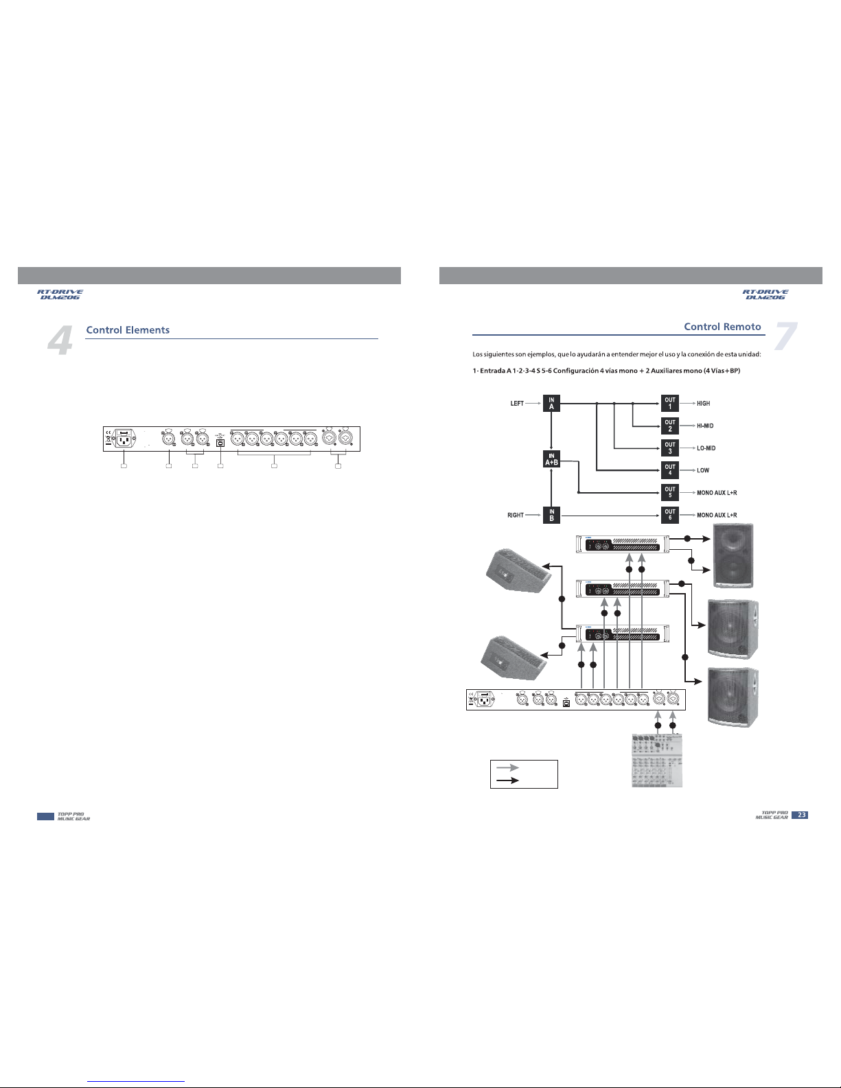
This switch is used to turn the main power ON / OFF.
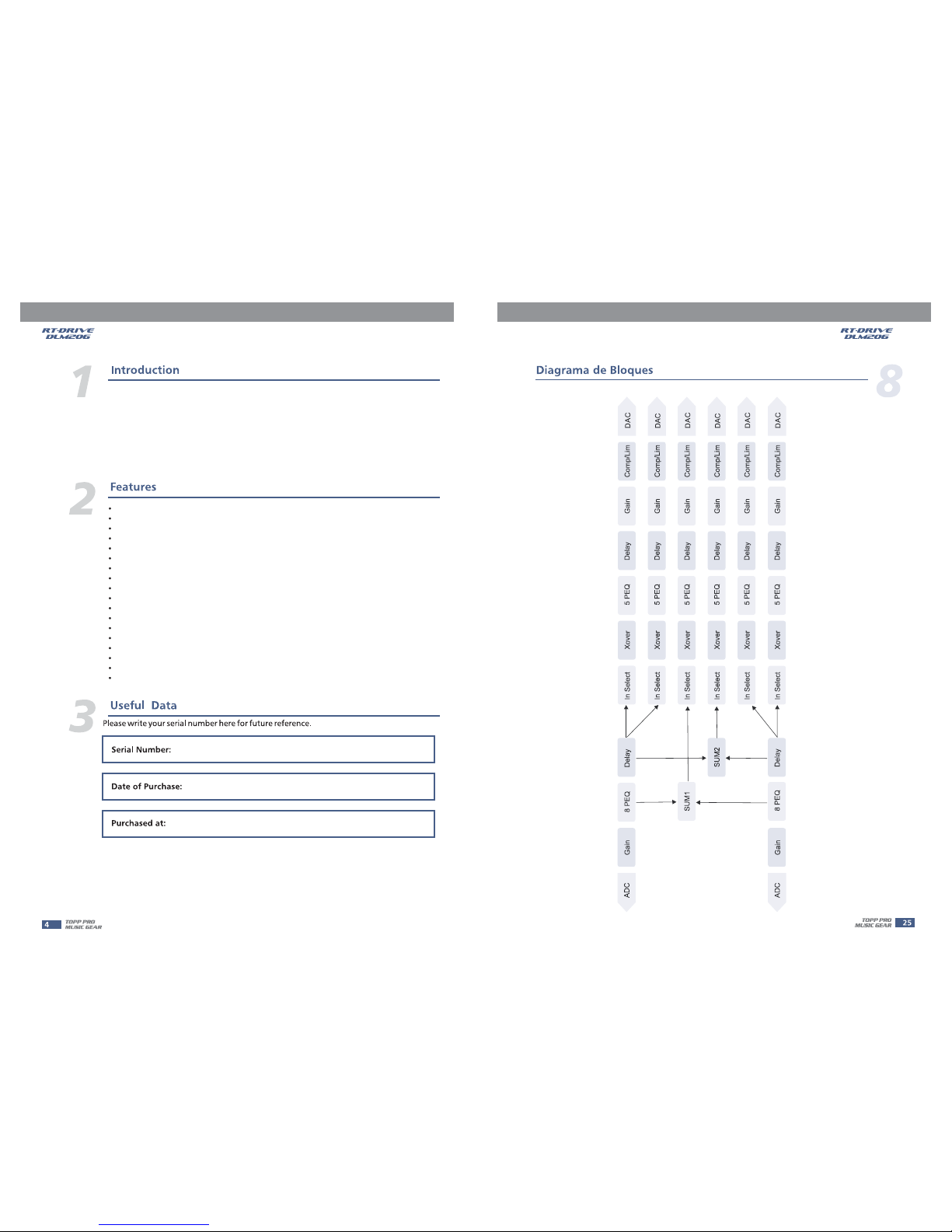
As the input gain control, the control range is from +12dB to -40 dB, it includes 8-band Parametric EQ
and Delay for adjustment. Due to the Gain is adjusted by digital, user can set the input leve l to
suit the application. But becareful not to set the volume too high to let the signal clipped.
As the output gain control, the control range is from +12 dB to -40 dB, it includes Input selection, Crossover,
5-band Parametric EQ, Delay, Gain and Compress / Limit functions. Due to the Gain is adjusted by digital,
user can adjust the output level to appropriate situation. The output level display was useful to the
gain setting, as it can avoid the volume too high to let the signal clipped.
Several functions parameters setting, such as ID number setting, Digital and Analog Input selection are
used for different application.
1
2 3
4
5
6
7
89
1011
12
13
IN
OUT
UTIL
POWER
PASS
EXIT
LOAD
SAVE
ENTER
CONTROL PANEL
PARAMETER
6
MUTE
OUTPUT
LEVEL
5
MUTE
CLIP
3
6
24
30
12
LIMIT
OUTPUT
LEVEL
4
MUTE
CLIP
3
6
24
30
12
LIMIT
OUTPUT
LEVEL
23
MUTE MUTE
OUTPUT
LEVEL
OUTPUT
LEVEL
MUTE
1
OUTPUT
LEVEL
A
CLIP
3
6
18
24
30
12
CLIP
3
6
18
24
12
B
30
R
CLIP
3
6
24
30
12
LIMIT
CLIP
3
6
24
30
12
LIMIT
CLIP
3
6
24
30
12
LIMIT
CLIP
3
6
24
30
12
LIMIT
RT-DRIVE
DLM-206
FRONT PANEL
1. POWER ON / OFF
2. INPUT
3. OUTPUT
4. UTILITY
5
5. Edit Controls
These two buttons allow you to turn over the pages and/or a variable number of parameters.
6.LOAD&SAVE
These buttons are used to load and save the user's presets. Up to 80 presets can be used for
parameters setting.(10 Factory Presets and 70 User's Presets)
7.PASS/EXIT
The button ''PASS'' is used to bypass the DSP PEQ, HP / LP, and Volume functions, also send the
input signal to the RT-DRIVE DLM-206 outputs directly. The button ''EXIT'' is used to return to
previous operation.
8. ENTER Control
This control is used to select the preset and modify the parameter's value.
9. Parameter Display
All the functions' parameters setting are showing on the 2 16 characters LCD display. U se r ca n
combine Enter control and function buttons for different channels and parameters setting.
10. MUTE Button
All the output channels have mute button with on / off LED display for the quick silence function.
The default mute function was enabled when power on the unit.
11. OUTPUT LEVEL Meter
The entire outputs' channels have level display to indicate the signal level on the panel. The output
limiter function also display on it when it was enabled.