LAWO ruby User manual

ruby
User Manual
Version: 6.0.0/4
To obtain the latest documentation and software downloads, please visit:
www.lawo.com/downloads
Edition: 18 January 2018

Copyright
All rights reserved. Permission to reprint or electronically reproduce any document or graphic in whole or
in part for any reason is expressly prohibited, unless prior written consent is obtained from the Lawo AG.
All trademarks and registered trademarks belong to their respective owners. It cannot be guaranteed that
all product names, products, trademarks, requisitions, regulations, guidelines, specifications and norms
are free from trade mark rights of third parties.
All entries in this document have been thoroughly checked; however no guarantee for correctness can be
given. Lawo AG cannot be held responsible for any misleading or incorrect information provided throughout
this manual.
Lawo AG reserves the right to change specifications at any time without notice.
© Lawo AG, 2018

3/82
Table of Contents
rubyUser Manual Version: 6.0.0/4
Table of Contents
1. Introduction ......................................................................................................................................... 5
2. Important Safety Instructions ................................................................................................................ 6
3. The Hardware ...................................................................................................................................... 8
3.1 System Components .................................................................................................................. 9
3.2 DSP Core Compatibility ............................................................................................................. 10
3.3 Controls Overview ..................................................................................................................... 11
3.4 Control Surface Variants ............................................................................................................ 14
3.5 Placement Options ................................................................................................................... 16
3.6 Accessories ............................................................................................................................. 17
4. Installation ......................................................................................................................................... 18
4.1 Preparation .............................................................................................................................. 19
4.2 Installing Countersunk Frames ................................................................................................... 20
4.3 Wiring ...................................................................................................................................... 21
4.4 Working with the CAN Bus ........................................................................................................ 23
4.5 CAN Bus Addressing ................................................................................................................ 24
4.6 Powering the Device .................................................................................................................. 26
4.7 Exchanging the MF Key Labels ................................................................................................. 27
5. Operation .......................................................................................................................................... 28
5.1 The Fader Strip ......................................................................................................................... 29
5.2 The Central Module(s) ............................................................................................................... 35
5.3 Assigning Fader Strips .............................................................................................................. 37
5.4 DSP Parameter Control ............................................................................................................. 39
5.5 Bus Assign .............................................................................................................................. 41
5.6 Conference Bussing (Mix Minus/N-1) .......................................................................................... 43
5.7 VCA Grouping .......................................................................................................................... 45
5.8 Pool & RAVENNA Sources ....................................................................................................... 47
5.9 Working with Layers ................................................................................................................. 50
5.10 Fader Mappings ........................................................................................................................ 52
5.11 Configurable Surface Functions .................................................................................................. 53
5.12 Snapshots ............................................................................................................................... 55
5.13 The SYS Menu ......................................................................................................................... 58

rubyUser Manual
Table of Contents
4/82 Version: 6.0.0/4
6. Maintenance ...................................................................................................................................... 60
6.1 Checking the Hardware Status ................................................................................................... 61
6.2 Updating Firmware .................................................................................................................... 62
6.3 The Special Functions Mode ...................................................................................................... 63
6.4 Replacing Defective Parts .......................................................................................................... 69
6.5 Locating the Control Surface Serial Number ................................................................................ 70
6.6 Cleaning the Control Surface ...................................................................................................... 71
7. Trouble-shooting ................................................................................................................................ 72
7.1 Solving Connectivity Issues ........................................................................................................ 73
8. Appendices ....................................................................................................................................... 74
8.1 Part Numbers ........................................................................................................................... 75
8.2 Dimension Drawings ................................................................................................................. 76
8.3 Connector Pin-Outs .................................................................................................................. 77
8.4 The 12V DC Power Supply ........................................................................................................ 78
8.5 The User Labels Software .......................................................................................................... 79

rubyUser Manual Version: 6.0.0/4 5/82
1. Introduction
1. Introduction
Welcome to ruby.
About this Manual
This document describes all aspects of the ruby control surface, including its hardware components, installation,
connections, operation and maintenance. The specification is valid for Version 6.0.0.x.
The surface requires a DSP Core such as POWER CORE and, optionally, may run with a VisTool MK2 touch-
screen interface. You can find more information on these products in the relevant manuals.
All Lawo manuals are available from the Download-Center at www.lawo.com (after Login).
Look out for the following which indicate:
Notes - points of clarification.
Tips - useful tips and short cuts.
WARNINGS: Alert you when an action should always be observed!
Lawo User Registration
For access to the Download-Center and to receive regular product updates, please register at:
www.lawo.com/user-registration.

rubyUser ManualVersion: 6.0.0/46/82
2. Important Safety Instructions
2. Important Safety Instructions
General Safety
Warning
Exposure to excessive sound pressure levels can lead to impaired hearing and cause damage to the ear.
Please read and observe ALL of the following notes:
·
Check all of the hardware devices for transport damage.
·
Any devices showing signs of mechanical damage or damage from the spillage of liquids MUST NOT
be connected to the mains supply or disconnected from the mains immediately by pulling out the
power lead.
·
All devices MUST be grounded. Grounding connectors are provided on all devices. In addition, all low-
voltage devices external to the system must also be grounded before operation.
·
For Scandinavian countries, ALWAYS use a grounded mains connection, to prevent the device from
being grounded through Ethernet or other signal connections.
·
Do NOT use the system at extreme temperatures - observe the temperature range and humidity
specified in the installation instructions.
·
Do NOT expose devices to liquids which may drip or splash.
·
Do NOT place objects filled with liquids, such as vases, upon a device.
·
Only service staff may replace batteries.
·
CAUTION: Danger of explosion if battery is incorrectly replaced - Replace only with the same or
equivalent type.
Servicing of components inside a device MUST only be carried out by qualified service personnel according to
the following guidelines:
·
Before removing parts of the casing, shields, etc. the device MUST be switched off and disconnected
from all mains.
·
Before opening a device, the power supply capacitor MUST be discharged with a suitable resistor.
·
Components that carry heavy electrical loads, such as power transistors and resistors, should NOT
be touched until cool to avoid burns.
Servicing unprotected powered devices may only be carried out by qualified service personnel at their own
risk. The following instructions MUST be observed:
·
NEVER touch bare wires or circuitry.
·
Use insulated tools ONLY.
·
DO NOT touch metal semi-conductor casings as they can bear high voltages.
Eye Safety
Warning
This equipment may use Class 1 Laser products which emit invisible laser radiation that may lead to eye
injury.
·
NEVER look directly into optical components or optical fibre cables.
·
Fit protection caps to close any unused optical components.
·
Connect all optical fibre cables BEFORE turning on the equipment.

rubyUser Manual Version: 6.0.0/4 7/82
2. Important Safety Instructions
Defective Parts/Modules
Warning
ruby contains no user-serviceable parts. Therefore DO NOT open the devices other than to perform the
procedures described in this manual.
In the event of a hardware defect, please send the system component to your local service representative
together with a detailed description of the fault. We would like to remind you to please check carefully
whether the failure is caused by erroneous configuration, operation or connection before sending parts for
repair. Please contact our service department before sending parts for repair.
First Aid (in the case of electric shock)
Warning
DO NOT touch the person or his/her clothing before power is turned off, otherwise you risk sustaining an
electric shock yourself.
Separate the person as quickly as possible from the electric power source as follows:
·
Switch off the equipment.
·
Unplug or disconnect the mains cable.
·
Move the person away from the power source by using dry insulating material (such as wood or
plastic).
If the person is unconscious:
·
Check their pulse and reanimate if their respiration is poor.
·
Lay the body down and turn it to one side. Call for a doctor immediately.
Having sustained an electric shock, ALWAYS consult a doctor.
rubyUser ManualVersion: 6.0.0/48/82
3. The Hardware
3. The Hardware
This chapter describes the system components, controls, options and accessories.
Topics include:
·
System Components
·
DSP Core Compatibility
·
Controls Overview
·
Control Surface Variants
·
Placement Options
·
Accessories

rubyUser Manual Version: 6.0.0/4 9/82
3. The Hardware
3.1 System Components
A complete system consists of up to four components:
·
ruby Control Surface (essential) – available in single or split-frame configurations.
·
DSP Core (essential) – all audio interfacing, routing, control and signal processing.
·
VisTool MK2 (optional) – runs on an external PC to provide real-time displays and touch-screen control.
·
Key Panels (optional) – a range of panels offering additional keys and talkback control.
This document describes the ruby control surface.
For more information on other components, such as the DSP Core or VisTool MK2, please refer to the manuals
for those products.
rubyUser ManualVersion: 6.0.0/410/82
3. The Hardware
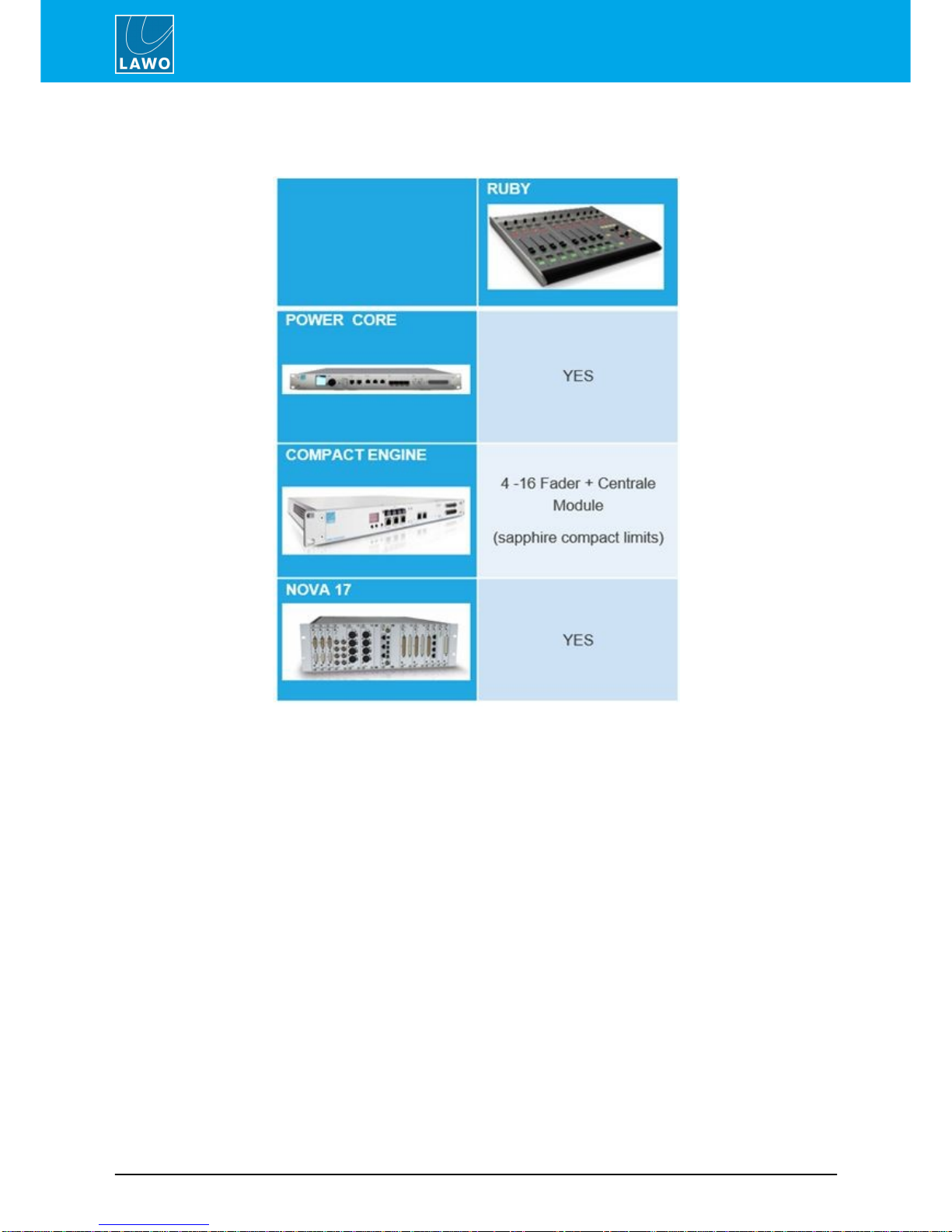
3.2 DSP Core Compatibility
The ruby control surface is compatible with the following DSP Core products:

rubyUser Manual Version: 6.0.0/4 11/82
3. The Hardware
3.3 Controls Overview
Each control surface consists of at least one Fader Module (with 4 fader strips), a single Central Module, and up
to 6 additional Central Modules running in monitor mode.
Some of the control functionality is fixed (system-defined), while some is programmable by the configuration.
3.3.1 Fader Modules
Fader Module
Each Fader Module provides four identical fader strips, each with an ACCESS key, 100mm motorised fader,
backlight and label display.
The upper section includes a rotary control and four small MF Keys (1, 1a, 2, 2b). Their functions are labeled by
the OLED displays.
There are then three large MF Keys (3, 4, 5) with foil-printed labels.
All MF Keys are defined by the configuration.
rubyUser ManualVersion: 6.0.0/412/82
3. The Hardware
3.3.2 Central Modules
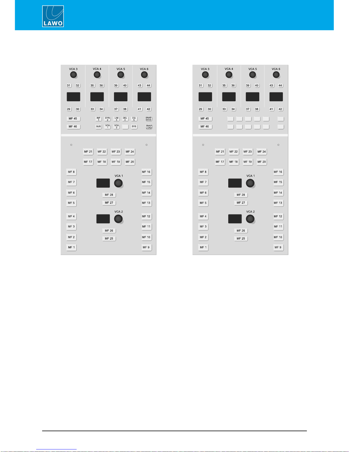
The Central Module (full mode)
Central Module (monitor mode)
Each control surface must include one Central Module. If additional Central Modules exist, then these must run in
monitor mode.
The Central Module (full mode)
The upper section includes four sets of rotary encoders and small MF Keys which interact with the 12 Function
Buttons: INP, DYN,LIM, etc. Their functions are labeled by the OLED displays. When none of the Function
Buttons are active, the controls are defined by the configuration (MF Keys 29 to 42 and VCAs 3 to 6). When a
Function Button is pressed, then the controls provide DSP parameter control, bus assign, system options and
snapshots. To the left are two large MF Keys (45 & 46) with foil-printed labels.
In the lower section are more large MF Keys (1 to 28) with foil-printed labels, and two rotary encoders (VCAs1, 2)
which are labeled by the displays.
All MF Keys and VCAs are defined by the configuration.
Central Modules (monitor mode)
Physically, these modules are identical to the full mode Central Module, but they provide slightly different
functionality.
Each module provides the same programmable MF Keys and VCA encoders, but in the upper section the 12
Function Buttons are NOT supported. This means that there is no access to DSP parameters, bus assign,
system options and snapshots. All controls are defined by the configuration. Note that the 12 Function Buttons
cannot be programmed by the configuration and, therefore, will remain blank.

rubyUser Manual Version: 6.0.0/4 13/82
3. The Hardware
3.3.3 Programmable Functions
Programmable controls, such as MF Keys and VCA encoders, are defined by the configuration stored on the
DSP Core. They can be edited using the ON-AIR Designer software, allowing you to change the operation as
required.
In most cases, the large MF Keys are labeled by foil-printed labels and, by default, the control surface ships with
the labels for the standard template functions. If you change the MF Key functionality, then you will need to
exchange the foil-printed labels. Printed sheets with the most common labels are included with each control
surface frame.

rubyUser ManualVersion: 6.0.0/414/82
3. The Hardware
3.4 Control Surface Variants
8-fader single frame
12-fader split-frame
ruby can exist as a single or multi-frame control surface.
A choice of four main and five extender frames are available. Frames can be combined to increase the fader count
or create a split-frame surface. Each frame connects to the DSP Core via CAN bus, and is powered from its own
12V DC power supply (included). All frames include CAN BUS IN and CAN BUS LINK OUT connectors for easy
daisy-chaining.
In total, a single control surface can include any number of frames as long as the maximum number of faders
does not exceed 60.
One of the frames must include a Central Module but this can exist only once. Therefore, any additional Central
Modules will run in monitor mode. A single control surface can include up to 6 "monitor mode" Central Modules.
3.4.1 Main Frame Layouts
Four main frames are available. Each one includes a Central Module:
4-fader
8-fader
12-fader
16-fader
3.4.2 Extender Frame Layouts
Five extender frames can be added, either to increase the fader count or create a split-frame console.
4-fader extender
8-fader extender
12-fader extender
16-fader extender
Central Module ext.

rubyUser Manual Version: 6.0.0/4 15/82
3. The Hardware
3.4.3 Split-frame Configurations
By combining different frames, you can easily create a surface suitable for multiple operators.
In the example below, the surface includes three frames:
·
1 x 8-fader main frame (for the Assistant Operator)
·
1 x 12-fader main frame (for the Main Operator)
·
1 x 4-fader extender frame (for the Presenter)
By setting the correct CAN bus addresses, the order of fader strips and position of the Central Module is
flexible. In our example, the Main Operator's station can house the Central Module plus fader strips 1, 2, 3, etc,
even though its CAN bus is wired after the Assistant's station.
Multi-frame Configuration
A single control surface can support up to 60 faders, a single Central Module and up to 6 monitor mode
Central Modules.

rubyUser ManualVersion: 6.0.0/416/82
3. The Hardware
3.5 Placement Options
Each frame is available in one of three versions to provide different placement options. Note that the version must
be specified at the time of ordering; there is no possibility to convert the frame later.
Table Top
Countersunk
Countersunk Short
The differences in construction are:
·
Table Top - designed to be mounted on a table-top surface. This version includes a leather front buffer
and stylish side/rear profiles.
·
Countersunk - designed to fit flush within your studio furniture. This version comes with different front,
rear and side profiles.
·
Countersunk Short - the same as Countersunk but with shorter side profiles and no upper cover plate to
hide the cables (i.e. the rear panel connectors will be visible).

rubyUser Manual Version: 6.0.0/4 17/82
3. The Hardware
3.6 Accessories
Each control surface frame ships with the following additional items:
·
1 x external 12V DC power supply - to power the frame.
·
1 x 2m IEC power cable (country-specific) - to connect mains to the 12V DC power supply.
·
1 x 3m RJ45 cable - to connect the CAN bus from the surface to the DSP core or another frame.
·
Printed sheets with a selection of foil printed labels - to label the MF Keys.
If your control surface consists of multiple frames, then you will receive one set of accessories per frame (as every
frame requires its own power, CAN bus and MF Key labels).

rubyUser ManualVersion: 6.0.0/418/82
4. Installation
4. Installation
This chapter describes how to install the control surface.
Topics include:
·
Preparation
·
Installing Countersunk Frames
·
Wiring
·
Working with the CAN Bus
·
CAN Bus Addressing
·
Powering the Device
·
Exchanging the MF Key Labels

rubyUser Manual Version: 6.0.0/4 19/82
4. Installation
4.1 Preparation
A single control surface can consist of one or more frames.
Unpacking
Each frame is delivered in its own box with all included accessories.
Please check the contents of the shipping boxes, and in the event of any transport damage, contact your local
Lawo representative or email support@lawo.com.
Please take note of the Technical Data label, which includes your serial number, located on the underside of
each frame. Write down the serial number for your records BEFORE mounting!
Dimensions and Weight
The dimensions and weight of the frame depend on its size and version: table-top, countersunk or countersunk
short. Drawings for 8-fader frame versions are included in the Appendices. Drawings for other frame sizes are
available from the Download-Center at www.lawo.com (after Login).
Temperature and Cooling
The control surface is designed for normal studio installation and needs no special air conditioning.
Power Consumption & Electrical Voltage
Please see the 12V DC Power Supply appendix.

rubyUser ManualVersion: 6.0.0/420/82
4. Installation
4.2 Installing Countersunk Frames
Countersunk
Countersunk Short
Countersunk frames are optimized for easy countersunk mounting.
The frame has rounded-off edges so that it will fit smoothly into holes cut by a wood milling machine.
For the countersunk (regular) version, all cables can be hidden in the cable tray and connected to the console
inlets from the open underside of the tray.
For the countersunk short version, the table must be designed to provide a small opening in order to properly
cable the device.
All countersunk frames have flat side parts without edges. Therefore, the installer must provide some kind of
support onto which the surface will rest.
Please see the dimension drawings for details.
Other manuals for ruby
1
Table of contents
Other LAWO Music Mixer manuals


Popular Music Mixer manuals by other brands

SoundCraft
SoundCraft Delta Theatre user guide

Daktronics
Daktronics All Sport 5000 quick start guide

Automatic Technology
Automatic Technology C03M V1 installation instructions

SoundCraft
SoundCraft Si Performer 1 user guide

JBL
JBL 7510A Installation & technical guide

Mackie
Mackie Onyx 2480 supplementary guide


Telex Communications
Telex Communications Forum FOH user manual

Rodec
Rodec miXboX operating instructions

Mackie
Mackie Mackie Control Universal Pro quick start guide

Alto-Shaam
Alto-Shaam ZMX122FX quick start guide

AKG
AKG DMM14 U Reference manual

Studiomaster
Studiomaster Professional DJX 825 instruction manual