LB-Link BL-M8723DU1 User manual

Product Specification
Revision V1.0
Date 2018-05-25
Model Name BL-M8723DU1
Product Name IEEE 802.11b/g/n (1T1R) WIFI +Bluetooth
Bilian Approve Field
Engineer QC Sales
Customer Approve Field
Engineer QC Manufactory Purchasing
Shenzhen Bilian Electronic Co.,Ltd
Address: No 268,Fuqian Rd.,JuTang Community ,Guanlan Town,Baoan District, Shenzhen, 518110,PRC
Homepage: www.b-link.net.cn

0
Table of Contents
Revision History..................................................................................................................................................... 0
1. Introduction.........................................................................................................................................................1
1.1 General Description.......................................................................................................................... 1
1.2 Features................................................................................................................................................ 1
1.3 Applications........................................................................................................................................ 1
2. Functional Block Diagram..................................................................................................................................2
3. Product Technical Specifications........................................................................................................................ 2
3.1 General Specifications.................................................................................................................... 2
3.2 RF Specifications............................................................................................................................ 4
4. Pin Assignments..................................................................................................................................................5
5. Peripheral Schematic Reference Design............................................................................................................ 6
6. Mechanical Specifications..................................................................................................................................7
7. Others..................................................................................................................................................................8
7.1 Package Information.......................................................................................................................... 8
7.2 Storage Temperature and Humidity................................................................................................8
8. Typical Solder Reflow Profile............................................................................................................................8
Revision History
Date Document
Revision
Product
Revision
Description
/ 0.1 V0.1 Preliminary release
2017/05/21 1.0 V1.0 Officially released

1
1. Introduction
1.1 General Description
BL-M8723DU1 is a highly integrated single-chip 802.11n Wireless LAN (WLAN) USB2.0 Multi-Function
network interface controller with integrated Bluetooth 2.1//4.2 controller. It combines a WLAN MAC, a 1T1R
capable WLAN baseband, and RF in s single chip. The RTL8723DU provides a complete solution for a
high-performance integrated wireless and Bluetooth device. The integration provides better coordination
between 802.11 and Bluetooth, and with sophisticated dynamic power control and packet traffic arbitration,
RTL8723DU is able to provide the best coexistence performance Overview.
Top ViewFigure 1 Bottom ViewFigure 2
1.2 Features
Operating
Frequencies
:
BT:2.402~2.48GHz(BT)/WIFI:2.412~2.472GHz(USA 11Channels, Europe and others 13 channels)
Host Interface is USB, complies with USB 2.0
IEEE Standards : IEEE 802.11b/g/n
Wireless data rate can reach up to 150Mbps
Bluetooth controller complies with Bluetooth core specification V4.2
Connect to the external antenna through the half hole
Power Supply:3.3V±0.2V
1.3 Applications
MID
IP Camera
STB
Smart TV
E-book
Other devices which need to be supported by wireless network
11Channels, Europe and others 1

2
2. Functional Block Diagram
Figure 3 RTL8723DU block diagram
3. Product Technical Specifications
3.1 General Specifications
Item Description
Product Name BL-M8723DU1
Main Chip RTL8723DU-CG
Host Interface USB2.0
IEEE Standards IEEE 802.11b/g/n B T: Compatible with Bluetooth v2.1,v4.2 Systems
Operating Frequencies BT:2.402~2.48GHz(BT)/WIFI:2.412~2.472GHz(USA 11Channels, Europe and others 13 channels)
Modulation
WiFi:
802.11b:
CCK,
DQPSK,
DBPSK
802.11g:
64-QAM,16-QAM,
QPSK,
BPSK

3
802.11n: 64-QAM,16-QAM, QPSK, BPSK
B T:
8DPSK, π/4 DQPSK, GFSK
Working Mode Infrastructure, Ad-Hoc
Wireless Data Rate
WIFI:
802.11b: 1, 2 ,5.5,11
802.11g: 6,9,12,18,24,36,48,54
802.11n: MCS0~7,HT20 reach up to72.2Mbps, HT40 reach up to150Mbps
BT:
1 Mbps for Basic Rate
2,3 Mbps for Enhanced Data Rate
Rx Sensitivity WIFI:-94dBm (Min) BT: -89dBm (Min)
TX Power WIFI:16.93dBm
(Max)
BT:
4.85dBm
(Max)
Antenna Type Connect to the external antenna through the half hole
Dimension(L*W*H) (PCB) 12.2mm*12.9mm*0.8mm (L*W*H) ,Tolerance: ±0.15mm
Power Supply 3.3V±0.2V
Clock Source 40MHz
Working Temperature -10°C to +50°C
Storage Temperature -40°C to +70°C
ESD CAUTION:Although this module is designed to be as robust as possible, Electrostatic Discharge (ESD)
can damage this module. It must be protected from ESD at all times and handled under the protection of ESD.
3.2 DC Power Consumption
Vcc=3.3V,Ta= 25 °C,unit: mA
Supply current Typ. Max
Standby (RF disabled) 75 80
802.11b 1Mbps 11Mbps
Supply current Typ. Max. Typ. Max.
TX mode 320 330 285 300
Rx mode 89 90 90 92
802.11g 6Mbps 54Mbps
Supply current Typ. Max. Typ. Max.
TX mode 260 270 190 205
Rx mode 89 90 92 95

4
802.11n HT20 MCS0 MCS7
Supply current Typ. Max. Typ. Max.
TX mode 250 260 185 200
Rx mode 89 91 92 96
802.11n HT40 MCS0 MCS7
Supply current Typ. Max. Typ. Max.
TX mode 240 250 180 190
Rx mode 90 92 95 99
3.3 RF Specifications
TX Constellation Error(EVM)
802.11b: <-20dB@11Mbps
802.11g:<-28dB@54Mbps
802.11n-HT20: <-28dB@72.2Mbps
802.11n-HT40:< -28dB@150Mbps
Receiver Minimum Input Sensitivity@PER
1Mbps: -92dBm@PER<8%;
11Mbps:-85dBm@PER<8%;
54Mbps:-72dBm@PER<10%;
150Mbps:-66dBm@PER<10%;
BT: -89dBm@1Mbps -85dBm@2Mbps
-83dBm@3Mbps

5
4. Pin Assignments
Figure 4 Pin Assignments (Top view)
Pin No. Pin Name Description
1 GND Grond
2 RF-S0 WLAN/BT RF TX/RX signal port 0
3 RF-S1
4 GND Grond
5 BT_PCM_IN General Purpose Input/Output Pin
6 BT_PCM_OUT General Purpose Input/Output Pin
7 BT_PCM_SYNC General Purpose Input/Output Pin
8 BT_PCM_CLK General Purpose Input/Output Pin
9 BT_WAKE_HST Chip wakeup host
10 HST_WAKE_BT host wakeup Chip
11 VDD33 The power input 3.3V
WLAN/BT RF TX/RX signal port 1(No signal transmission)

6
12
DM
High-Speed USB D- Signal
12
DP
High-Speed USB D+ Signal
14
GND
Grond
15
N
No attributes
16
WL_DIS#
This Pin Can Externally Shutdown the RTL8723DU
WLAN function when WL_DISn is Pulled Low. When this pin
deasserted,USB interface will be disabled.
The WLAN Radio-off function with host interface
remaining connected.
17
BT_DIS#
This Pin Can Externally Shutdown the RTL8723DU
BT function when BT_DISn is Pulled Low. This pin can
also support the BT Radio-off function with host
interface remaining connected.
18
N
No attributes
19
HST_WAKE_WL
General Purpose Input/Output Pin
20
WL_WAKE_HST
General Purpose Input/Output Pin
21,22
N
No attributes
5. Peripheral Schematic Reference Design
Circuit reference pictures were designed
Note: 1.Pls reserve a “pi” circuit for antenna matching.
2. The RF circuit needs to keep 50 Ω impedance.
3. The USB differential pair needs to keep 90 Ω impedance.
4. reserved filter capacitance for 3.3 V power input

7
6. Mechanical Specifications
PCB Module dimension: Typical ( L*W * H): 12.2mm*12.9mm*0.8mm Tolerance : +/-0.15mm
Figure 5
Figure 6
8
7. Others
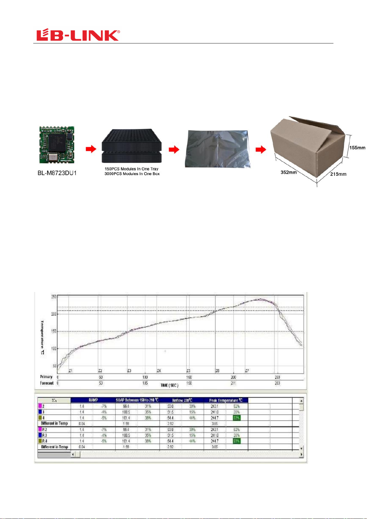
7.1 Package Information
Figure 7 Package Information
7.2 Storage Temperature and Humidity
Storage Condition: Moisture barrier bag must be stored under 30℃, humidity under 85% RH.
The calculated shelf life for the dry packed product shall be a 12 months from the bag seal date.
Humidity indicator cards must be blue, <30%.
8. Typical Solder Reflow Profile
Figure 7

FCC Statement
This device complies with part
15
of
the FCC rules. Operation
is
subject
to
the following two conditions:
(1)
thi
s device may not cause harmful interference,
and
(2) this device must accept any interference received,
incl
uding
interference that may
cause undesired operation.
Changes
or
modifications not expressly approved
by
the party responsible for compliance could void the
user’
s authority
to
operate the equipment.
NOTE: This equipment
has
been tested
and
found
to
comply with the limits for a Class B digital device, pursua
nt
to
part
15
of
the FCC Rules. These limits are designed
to
provide reasonable protection against harmful inte
rference
in
a residential installation. This equipment generates uses
and
can radiate radio frequency energy a
nd,
if
not installed
and
used
in
accordance with the instructions, may cause harmful interference
to
radio com
munications. However, there
is
no
guarantee that interference will not occur
in
a particular installation.
If
this
equipment does cause harmful interference
to
radio
or
television reception, which can
be
determined
by
turn
ing
the equipment off
and
on, the user
is
encouraged
to
try
to
correct the interference
by
one
or
more
of
the
following measures:
‐
Reorient
or
relocate the receiving antenna.
‐
Increase the separation between the equipment and receiver.
‐Connect the equipment into an outlet on a circuit different from that to which the receiver is connected.
‐Consult the dealer
or
an
experienced radio/TV technician for help important announcement
Important Note:
Radiation Exposure Statement
This equipment complies with FCC radiation exposure limits set forth for an uncontrolled environment. This
equipment should be installed and operated with minimum distance 20cm between the radiator and your
body.
This transmitter must not be co-located or operating in conjunction with any other antenna or transmitter.
Country Code selection feature to be disabled for products marketed to the US/Canada.
This device is intended only for OEM integrators under the following conditions:
1. The antenna must be installed such that 20 cm is maintained between the antenna and users, and
2. The transmitter module may not be co-located with any other transmitter or antenna,
3. For all products market in US, OEM has to limit the operation channels in CH1 to CH11 for 2.4G band
by supplied firmware programming tool. OEM shall not supply any tool or info to the end-user
regarding to Regulatory Domain change. (if modular only test Channel 1-11)
As long as the three conditions above are met, further transmitter testing will not be required. However, the
OEM integrator is still responsible for testing their end-product for any additional compliance requirements
required with this module installed.
Important Note:
In the event that these conditions cannot be met (for example certain laptop configurations or co-location
with another transmitter), then the FCC authorization is no longer considered valid and the FCC ID cannot be
used on the final product. In these circumstances, the OEM integrator will be responsible for re-evaluating the
end product (including the transmitter) and obtaining a separate FCC authorization.
End Product Labeling
The final end product must be labeled in a visible area with the following" Contains FCC ID: 2AL6KBL-
M8723DU1 "
Manual Information to the End User
The OEM integrator has to be aware not to provide information to the end user regarding how to install or
remove this RF module in the user’s manual of the end product which integrates this module.
The end user manual shall include all required regulatory information/warning as show in this manual.

Integration instructions for host product manufacturers according to KDB 996369 D03 OEM
Manual v01
2.2 List of applicable FCC rules
CFR 47 FCC PART 15 SUBPART C has been investigated. It is applicable to the modular transmitter
2.3 Specific operational use conditions
This module
is stand-alone modular.
If the
end
product
will
involve
the
Multiple simultaneously
transmitting condition
or
different
operational conditions for a stand-alone modular transmitter in a host, host manufacturer have to consult with module manufacturer
for the installation method in end system.
2.4 Limited module procedures
This module is Limited single modular without shielding, host manufacturer have to consult with module manufacturer for the module
limiting conditions when integrate the module in the host. module manufacturer should reviews detailed test data or host designs
prior to giving the host manufacturer approval.
2.5 Trace antenna designs
Not applicable
2.6 RF exposure considerations
This equipment complies with FCC radiation exposure limits set forth for an uncontrolled environment. This equipment should be
installed and operated with minimum distance 20cm between the radiator & your body.
2.7 Antennas
This radio transmitter 2AL6KBL-M8723DU1 has been approved by Federal Communications Commission to operate with the
antenna types listed below, with the maximum permissible gain indicated. Antenna types not included in this list that have a gain
greater than the maximum gain indicated for any type listed are strictly prohibited for use with this device.
Model Type Connector
Peak gain ( dBi )
2400-2483.5
MHz
5150-5250
MHz
5250-5350
MHz
5470-5725
MHz
5800
MHz
2400-2483.5
MHz
PIFA/
Di
pole
/ 2.0 dBi / / / /
2.8 Label and compliance information
The final end product must be labeled in a visible area with the following" Contains FCC ID:2AVEDBL-M7668BU2".
2.9 Information on test modes and additional testing requirements
Host manufacturer which install this modular with limit modular approval should perform the test of radiated emission and spurious
emission according to FCC part 15C:15.247 and 15.209requirement, only if the test result comply with FCC part 15.247 and
15.209requirement, then the host can be sold legally.
2.10 Additional testing, Part 15 Subpart B disclaimer
Host manufacturer is responsible for compliance of the host system with module installed with all other applicable requirements for
the system such as Part 15 B.
Table of contents
Popular Network Card manuals by other brands

Multitech
Multitech RouteFinder RF802USB user guide

Panasonic
Panasonic TY-FB10WPU operating instructions

LaCie
LaCie 130822 - FireWire 400 ANF 800 USB 2.0 PCI Card... user manual

RTS
RTS AIO-BC-8-RJ45 Drawings Manual

Jinan USR IOT Technology
Jinan USR IOT Technology USR-WIFI232-A2 user manual

Global Sun Tech
Global Sun Tech WL MP 2454 1A3 user manual


