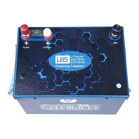
LBS LBS-12150-HP-REG Operation manual

MED HP Batteries –Installation & User Guide
Installation & User Guide
HP Batteries; Medium Size
0
Installation & User Guide
High Power (HP) Batteries
Medium Size
v2
Models:
LBS-12150-HP-REG
LBS-12150-HP-BIC
LBS-12200-HP-REG
LBS-12200-HP-BIC
LBS-12225-HP-REG
LBS-12225-HP-BIC
LBS-12300-HP-REG
LBS-12300-HP-BIC
LBS-2475-HP-REG
LBS-2475-HP-BIC
LBS-24110-HP-REG
LBS-24110-HP-BIC
LBS-24150-HP-REG
LBS-24150-HP-BIC
LBS-3675-HP-REG
LBS-3675-HP-BIC
LBS-4850-HP-REG
LBS-4850-HP-BIC
LBS-4875-HP-REG
LBS-4875-HP-BIC
Due to continuing improvements, the product you have purchased
may differ slightly from the products described herein.

MED HP Batteries –Installation & User Guide
Installation & User Guide
HP Batteries; Medium Size
1
Contents
1.0 Acronyms & Abbreviations..................................................................................................................................3
2.0 Introduction .................................................................................................................................................................4
3.0 Do’s and Don’ts ...........................................................................................................................................................5
2.1 Ensure the battery is physically secure.................................................................................................................5
2.2 Do not penetrate the battery enclosure ................................................................................................................5
2.3 Maintain an acceptable temperature range.........................................................................................................5
2.4 Avoid repeated shock and vibration.......................................................................................................................6
2.5 Avoid exposure to water or salt spray ...................................................................................................................6
2.6 Do not short circuit the battery.................................................................................................................................6
2.7 Mounting orientation ....................................................................................................................................................6
4.0 Longevity & Depth of Discharge........................................................................................................................7
4.1 Discharge Curve...............................................................................................................................................................7
5.0 Installation....................................................................................................................................................................9
5.1 Securing the Battery ......................................................................................................................................................9
Mounting orientation.......................................................................................................................................................9
5.2 Connecting the battery ..............................................................................................................................................10
Batteries OFF ....................................................................................................................................................................11
Connect Wiring ................................................................................................................................................................ 11
Connect Isolators/Breakers .......................................................................................................................................11
Batteries ON...................................................................................................................................................................... 11
Loads ON.............................................................................................................................................................................12
5.3 Anderson Plugs –BIC Version Only......................................................................................................................12
5.4 Voltmeters.......................................................................................................................................................................13
6.0 Battery User Guide.................................................................................................................................................14
6.1 Battery Management System ..................................................................................................................................14
6.2 BMS User Interface......................................................................................................................................................14
STATUS LED...................................................................................................................................................................... 15
Low Voltage Disconnect...............................................................................................................................................16
Short Circuit & Surge Overload.................................................................................................................................17
Comms reset:.........................................................................................................................................................................17

MED HP Batteries –Installation & User Guide
Installation & User Guide
HP Batteries; Medium Size
2
Repetitive Tripping........................................................................................................................................................18
Reset from Display Screen ..........................................................................................................................................18
Reset from Battery .........................................................................................................................................................18
START Button - Hibernation / Shutdown ............................................................................................................18
SHUTDOWN Button .......................................................................................................................................................18
BIC 1, 2, 3 LEDs................................................................................................................................................................19
COMMS Port ......................................................................................................................................................................19
7.0 Remote Monitoring Screen ........................................................................................................................................... 20
POWER Button.................................................................................................................................................................20
SETTINGS Button............................................................................................................................................................ 20
ENTER Button .................................................................................................................................................................. 20
Screen Pages ..........................................................................................................................................................................21
7.0 Specifications............................................................................................................................................................ 26
8.0 Contact Us ...................................................................................................................................................................27

MED HP Batteries –Installation & User Guide
Installation & User Guide
HP Batteries; Medium Size
3
1.0 Acronyms & Abbreviations
BIC Built-In-Controllers
BMS Battery Management System
HP High Power
LBS Lithium Battery Systems
REG Regular

MED HP Batteries –Installation & User Guide
Installation & User Guide
HP Batteries; Medium Size
4
2.0 Introduction
Congratulations! You have purchased a state-of-the-art lithium battery and we hope you enjoy many
years of trouble-free life. This Installation and User Guide describes how to connect and safely
operate the High Power (HP) range of Medium Size batteries.
The regular (REG) models (Figure 2b) contain no internal controllers. The BIC models (Figure 2a)
contain a built-in solar controller which can take direct solar panel input, and a DC Charge controller
that controls charging current from a vehicle alternator / start battery. (The BIC-DCS model, not
covered in this user guide, contains a further DC-DC charger to regulate charging from a vehicle with
a smart alternator.)
In the context of this guide, the term High Power (HP) refers to the BMS charge and discharge
current capability. In most models the BMS allows charging at up to 150A and discharge at 200A
continuous / 500A surge.
As with all batteries, you should consider the mechanical and environmental conditions that you
intend to operate the battery in to maximise overall performance and achieve the longest battery
life. LBS offer these general guidelines; however, you should seek LBS advice or that of a qualified
electrical tradesperson if you are in doubt.
Figure 2a
LBS-*****-HP-BIC
Figure 2b
LBS-*****-HP-REG

MED HP Batteries –Installation & User Guide
Installation & User Guide
HP Batteries; Medium Size
5
3.0 Do’s and Don’ts
This battery contains lithium iron phosphate (LFP) cells. While LFP cells are the safest Li-Ion
chemistry, the stored chemical energy represents a risk of fire, burns or explosion if misused.
Avoid injury to yourself and others, adhere to the warnings in this Guide.
•Avoid mechanical shock
•Do not expose to fire
•Do not pierce battery
•Do not disassemble
•Do not drill into enclosure
•Do not short the terminals
•Do not allow water to enter
•Do not charge battery below 0oC
•Do not store battery below -20oC or above 60oC
2.1 Ensure the battery is physically secure
Even though lithium batteries are light weight in comparison to lead acid, they can still become a
dangerous projectile in a moving vehicle, RV, cart or boat if not secured. Ensure the battery is safely
secured before travel. If in doubt seek LBS advice and consider making use of LBS mounting brackets
to safely secure the battery.
2.2 Do not penetrate the battery enclosure
You may be tempted to drill into the aluminium enclosure to secure mounting brackets. Doing so
may inadvertently penetrate one of the cells which could cause thermal runaway and vapour
emissions. Do not under any circumstances drill or penetrate into the enclosure. Use only existing
mounting holes in the battery and short screw lengths no greater than 13mm.
We strongly recommend the LBS mounting kit with screws and brackets that are designed to safely
attach to the battery; alternatively use strapping and clamping to secure the battery in place.
2.3 Maintain an acceptable temperature range
Like all batteries, LBS batteries operate and perform the best, as well as last the longest, in a cool
and stable temperature environment of between 10oC and 25oC. The maximum window of
acceptable operation is 0-45oC.
If you regularly operate outside of this suggested range you should consider changing the battery
location or actively cool or heat the environment in order to preserve battery life. If the ambient
temperature that the battery operates in is greater than 60oC you should cease use immediately.
Operating outside of these guidelines diminishes the life and performance of the battery and voids
the warranty.

MED HP Batteries –Installation & User Guide
Installation & User Guide
HP Batteries; Medium Size
6
2.4 Avoid repeated shock and vibration
Whilst the battery is robustly constructed and protected in an aluminium enclosure, it is not
designed to operate continuously in high shock or high vibration environments. Normal use in a
4WD environment is acceptable and the battery has been designed in accordance with these
expected conditions. However, dropping the battery or exposing the battery to a high number of
excessive vibrations may lead to a fault or failure of the battery.
2.5 Avoid exposure to water or salt spray
Whilst the battery is mechanically protected, the enclosure is only IP20 equivalent and is not
designed for a wet environment. Do not submerge the battery in water or expose the battery to
direct water spray. If it is likely that a water will be on the floor where the battery is located, ensure
the battery is facing upwards with the terminals (and electronics) on the top, so that any water that
gets into the bottom can drain out again without touching the electronics.
Avoid exposing the battery long term to salty water spray such as in a marine environment to avoid
corrosion. Salt laden air may also cause corrosion in the long term; therefore, minimise exposure by
installing the battery in a protected hatch or compartment.
2.6 Do not short circuit the battery
Whilst the BMS will protect the internal cells from short circuit, it is highly recommended to avoid
short circuiting the battery. Appropriately sized external fuses should be used where possible.
Pay attention when using metallic tools in the vicinity of the terminals, as accidentally contacting the
positive and negative terminal with a metallic object like a spanner will cause a short circuit and
spark. Always keep the plastic caps screwed on when not using the terminals.
Always perform work on passive wiring first and connect the live battery as the last connection. If
you have to, when working on live circuits, exercise due care and use insulated tools where possible.
If you are unsure how to install the battery, seek advice from LBS or a suitably qualified electrical
tradesperson.
2.7 Mounting orientation
The typical operating orientation is with the terminals facing upwards and should be the first option
if possible. Having the battery terminals facing forwards is also an acceptable orientation. The
battery uses the aluminium lid as a heat sink, the function of which can be hampered by an upside-
down orientation; therefore, mounting upside down is not recommended. If in doubt, contact LBS or
a suitable tradesperson for advice.
IF THE SUPPLIED MOUNTING BRACKETS ARE NOT SUITABLE, USE EXTERNALLY SUPPORTED
STRAPPING OR BRACKETS. DO NOT DRILL INTO THE BATTERY ENCLOSURE OR REMOVE RIVETS FROM
THE BATTERY ENCLOSURE. IF METAL SHAVINGS OR PIECES OF METAL FROM REMOVED RIVETS FALL
INTO THE ELECTRONICS, THIS WILL CAUSE DAMAGE AND VOID THE BATTERY WARRANTY.

MED HP Batteries –Installation & User Guide
Installation & User Guide
HP Batteries; Medium Size
7
4.0 Longevity & Depth of Discharge
One of the advantages of lithium batteries over lead-acid batteries is longevity. If you want to realise
the long life potential out of your lithium battery, then consideration must be given to depth of
discharge.
The electronics inside the battery enclosure is designed to monitor the charge –if you connect a
solar panel to your battery for the purpose of maintaining 100% charge, this will be switched on
when needed. You do not have to keep a constant watch on the screen display –a constant green
LED on the battery display panel means that the battery is charging. The internal electronics are
working to protect the battery from being overcharged, as well as when the battery is close to
empty.
When the battery is supplying current to a connected device such as an inverter, the green LED on
the battery display marked ‘STAT’ will continuously flash on and off every second.
For example, if you have solar panels continuously connected to your battery, the electronics will
not allow the battery to remain at a maximum charge level. Keeping your battery at a maximum is
not as important as it is for lead acid batteries.
A battery lifespan is rated by the number of cycles before the original capacity has reduced by a
certain amount; a cycle is defined as discharging from fully charged, to a percentage Depth of
Discharge (DOD), and then charging back to full again. So, DOD describes what percentage of the
battery capacity is being used each time.
Note: DOD is different to State of Charge (SOC, also known as Charge Level); in fact, they add
together to 100%. So, 80% DOD equates to 20% SOC.
The less DOD you use each cycle, the longer the battery will last.
This fact should be considered when choosing the battery Amp hour capacity. You will have a higher
return on battery investment if there is enough capacity at hand such that you are not heavily
discharging the battery on every cycle. Extra capacity ensures lower DOD, extended life and a higher
financial return on your investment.
LBS batteries have a cycle life of 5,000 at 50% and 2,000 at 80% DOD.
4.1 Discharge Curve
Note that unlike lead acid batteries, lithium batteries hold their voltage over the cycle, dropping off
only when the battery is about 90% discharged, as indicated in Figure 4-1 for illustrative purposes.

MED HP Batteries –Installation & User Guide
Installation & User Guide
HP Batteries; Medium Size
8
Figure 4-1 –Volt Curve Lead Acid vs Lithium
0
2
4
6
8
10
12
14
16
0% 10% 20% 30% 40% 50% 60% 70% 80% 90% 100%
Battery Voltage (V)
Depth of Discharge (DoD)
Discharge Curve: Lithium vs Lead Acid
Lead Acid Voltage (v) Lithium Voltage (V)

MED HP Batteries –Installation & User Guide
Installation & User Guide
HP Batteries; Medium Size
9
5.0 Installation
5.1 Securing the Battery
It is strongly recommended to use the LBS purpose made
mounting brackets and screws to secure the battery in its
permanent location. The battery enclosure has been
specifically designed with pre-drilled holes to locate
aluminium angle brackets at various points to suit
different compartments, locations and battery orientation
(terminals facing up or terminals facing to the side).
Figure 5-1: Battery Mounting Bracket Options
Unsecured batteries in moving vehicles represent a projectile hazard in the event of an accident.
Refer to the specific battery model datasheet for mounting bracket options. As mentioned earlier in
section 2, do not remove rivets or penetrate the enclosure in any way –drilling holes into the
enclosure or removing rivets to mount brackets will cause metal shavings to interfere with the
electronics inside.
Mounting orientation
The typical operating orientation is with the terminals facing upwards and should be the first option
if possible. Having the battery terminals facing forwards is also an acceptable orientation. The
battery uses the aluminium lid as a heat sink, the function of which can be hampered by an upside-
down orientation; therefore, mounting upside down is not recommended. If in doubt, contact LBS or
a suitable tradesperson for advice.

MED HP Batteries –Installation & User Guide
Installation & User Guide
HP Batteries; Medium Size
10
5.2 Connecting the battery
All HP Medium batteries contains a red positive and black negative M10 terminal post. This is the
main connection point for all loads. Wiring for these should be connected in the order described
below.
Additional input options are available via Anderson plugs for the BIC and BIC-DCS models. The BIC-
DCS has an additional DC-DC charger option inside the enclosure and is not described in this user
guide.
Figure 5-2: High Power REG Battery
Figure 5-3: High Power BIC Battery

MED HP Batteries –Installation & User Guide
Installation & User Guide
HP Batteries; Medium Size
11
Batteries OFF
Firstly, ensure that all batteries are turned OFF.The LED backlight of the blue power switch will be
off, showing that charge and load has been disconnected.
Connect Wiring
Connect the positive terminal of the battery first and immediately replace the terminal cap, then
connect the negative terminal and immediately replace the terminal cap. Connect the ring
terminals over the terminal post and add the washer and nut and tighten securely (10Nm).
EXCESSIVE FORCE WILL DAMAGE THE TERMINAL MOUNTS. Replace each terminal cap so that it
locks tight with the nut. The red and black terminal caps are there for safety protection and to
prevent accidental shorting of the terminals from a metal object such as a spanner. TAKE CARE NOT
TO SHORT CIRCUIT THE BATTERY DIRECTLY BETWEEN THE POSITIVE AND NEGATIVE TERMINAL
POSTS, OR THE POSITIVE POST TO ANY METALLIC OBJECT!!!!
Connect Isolators
Turn ON / connect any isolation switches / circuit breakers / fuses to the inverter / motor controller.
We recommend not to use isolation switches or circuit breaker between the batteries and
inverter/motor controller, as this can cause issues with inrush currents into capacitors if the inverter is
connected when the battery is already on; this is detected by the BMS as a short circuit condition,
which may trip overload protection. Alternatively if there is an isolator switch / circuit breaker / fuse
between the battery and inverter, it should be connected before the battery is turned ON.
The batteries limit inrush current by using a soft-start function during the first few seconds after the
battery is turned on. However this relies on the inverter already being connected.
Other DC loads that draw current as soon as they are turned on may interfere with this soft-start
function; if possible they may need to be disconnected when the battery is first turned on.
Batteries ON
TURN ON THE BATTERY. This is the square blue POWER pushbutton inside the protective cover. If
the blue backlight behind the button is on, the battery is on as shown in Figure 5-1. If not, push the
button to turn the battery on. You can reset the battery by pressing the power button off and on again.
Resetting the battery is sometimes necessary when using ‘smart chargers’.

MED HP Batteries –Installation & User Guide
Installation & User Guide
HP Batteries; Medium Size
12
WHEN THE BATTERY IS INITIALLY TURNED ON, ALL THE GREEN LEDS WILL FLASH FOR A FEW
SECONDS. ONLY ONE LED WILL FLASH CONTINUOUSLY ON THE LEFT-HAND SIDE OF THE BATTERY
DISPLAY SCREEN. IF YOU SEE A RED FLASHING LED, THEN THERE IS A FAULT WITH THE BATTERY AND
YOU NEED TO REFER TO THE TABLE 6-1.
Once turned on, a single green LED will be on constantly while being charged. The square blue button
also remains illuminated.
When in a dormant state with no active load, a single green LED will flash every 5 seconds. The square
blue button also remains illuminated.
Loads ON
Large loads such as inverters and motor controllers can now be turned ON.
5.3 Anderson Plugs –BIC Version Only
On the left-hand side of BIC batteries there are four Anderson plug connections (grey, black, red and
blue). Black, blue, red plugs have overcurrent protection that will either restrict current to less than 45A,
or trip an error if current exceeds 45A.
The uses for these additional inputs are summarised below:
Grey: Directly connected to the main terminals to allow additional temporary
loads and charging sources to be connected to the battery when the terminal
posts are already occupied –eg another inverter (max 600W) or a folding
solar panel with integrated charge controller. Max current 50A in or out.
Black: Monitoring of external physically separate charger –could be:
•AC/mains charger
•Solar charger / charge controller / charge regulator
•DC-DC charger
Red: 12V (nominal) solar panel: max Voc ~24V (without a charge controller);
i.e. unregulated solar
Blue: DC charging from a 12V alternator or battery
With respect to DC charging from a 12V alternator, the BMS is programmed to block charge when
the cells are completely full, and continue to block charge until all cells are BELOW 3.35V. This is
done for 2 reasons:
•Cell lifespan is better when cells are not held at 100% for long periods, ie they last longer at
80% SOC. (In this way they are opposite to lead acid/AGM etc cells)
•To avoid high charge and discharge currents repeatedly turning on and off –this is not good
for charger electronics etc.

MED HP Batteries –Installation & User Guide
Installation & User Guide
HP Batteries; Medium Size
13
For example, if you notice that your lithium battery is not charging, put a load on this battery, or wait
a little longer. The max cell voltage will drop below 3.35V –this will reset the charge blocking and
allow charging again.
5.4 Voltmeters
Voltmeters are connected directly to the Anderson plugs they are next to, for diagnostic purposes.
Therefore, they show the voltage of whatever is plugged into that Anderson plug. They may also be
connected to the battery, in which case they will show the battery voltage. To check what voltage is
coming from a solar panel / vehicle alternator, etc. - just turn off the battery with the charging
source connected and read the voltmeter value.

MED HP Batteries –Installation & User Guide
Installation & User Guide
HP Batteries; Medium Size
14
6.0 Battery User Guide
6.1 Battery Management System
Your battery comes with a Battery Management System (BMS) mounted internally.
The BMS is an electronic solid-state circuit board which manages the cells and protects the battery
across a range of scenarios which primarily includes over charge and over discharge protection.
Unlike lead acid batteries, over charging or over discharging a lithium battery may lead to a
hazardous scenario. Therefore, the BMS is the heart and soul of a lithium battery.
The HP battery BMS is a highly reliable and functional solid-state device which is primarily designed
to keep the cells safe and the overall pack from being damaged by excessive voltage or excessive
discharge event.
In the context of this guide, the term High Power (HP) refers to the BMS charge and discharge
current capability. The BMS allows charging at up to 150A and discharge at 200A continuous or 500A
surge for <1 second.
Figure 6-1 HP BMS
6.2 BMS User Interface
The BMS user interface on the REG, BIC and BIC-DCS models is the same, and located as shown in
Figure 6-2. A clear plastic protective cover over the interface helps to protect from ingress of dust,
dirt, debris and any water.

MED HP Batteries –Installation & User Guide
Installation & User Guide
HP Batteries; Medium Size
15
Figure 6-2 BMS User Interface Location
A detailed view of the interface is illustrated in Figure 6-3 and shows a close-up of the Comms port,
Status LED, Shutdown Button, Start Button, Power button and BIC 1, 2, 3 LED status light which are
discussed below.
Figure 6-3 HP BMS User Interface
STATUS LED
Green solid = net charging,
green fast flashing = net discharging
green flash every 5 seconds = battery on, but no net current
BMS User
Interface

MED HP Batteries –Installation & User Guide
Installation & User Guide
HP Batteries; Medium Size
16
If the STATUS LED is flashing RED, this means the BMS has disconnected the battery because of some
Protection/issue and has gone into one of the following error states shown in Table 5-1 on page 16.
The issue is shown by the number # of flashes of the RED LED on the battery as follows (and
described on the remote Monitoring Screen).
# Flashes
of red LED
Description of Protection
Result
Action Required
0
Normal State
-
None
2
Low Voltage Disconnect (LVD)
CUV: Cell Under Voltage
Battery empty
Loads Disconnected
Connect charger;
Screen: Enter button, or
Battery: Power Button
3
BMS too hot
Loads & Charge
Disconnected
Reduce temperature;
wait to recover
4
Battery too cold
(UTD: Under Temperature Discharge.)
Loads Disconnected
Increase/Reduce
Temperature; wait to
recover
5
Battery too hot
(OTD: Over Temperature Discharge.)
6
Short Circuit
(Load current > 1000A for 70µs)
Loads Disconnected
Screen: Enter button, or
Battery: Power Button
7
Surge Overload
(Load current > 500A for 1 second)
8
Over Current
9
Communications issue
Screen readings
incorrect
Battery: Shutdown, then
Start button
10
Voltage Reading Mismatch (cells vs
pack)
Loads & Charge
Disconnected
Battery: Shutdown, then
Start button
Table 6-1 BMS Status Light Diagnostics
Apply the appropriate remedy as above –usually by pressing the power button off and on again, or
by pressing Enter on the Monitoring Screen.
Low Voltage Disconnect
The most common situation is #2 where the battery has been drained to empty and the Low Voltage
Disconnect (LVD) has occurred –in this case you should do the following:

MED HP Batteries –Installation & User Guide
Installation & User Guide
HP Batteries; Medium Size
17
1) Turn off all major loads (e.g. inverters, pumps etc.). Small loads such as lights and fridges are OK
to remain connected –provided that they draw less current than what the charger can supply.
However, all connected loads will draw current from the charger and so will reduce the rate at
which the battery charges.
2) Connect your charger(s) –maximum input current should be limited to 45 Amps.
3) If you have an LBS AC charger (or solar panels/alternator into an LBS BIC battery), this will
automatically charge the battery up to an acceptable level, after which the battery will connect
again. (Just check your AC mains/shore power is connected and switched on!)
4) If you have another brand of charger, it may not charge automatically until it can “see” the
battery, which means you may need to reset the battery before your charger will begin charging.
You can reset the battery by pressing the power button off and on again, or by pressing Enter on
the Monitoring Screen. This will allow 1 minute for the charger to start up and start charging.
5) You may also need to reset your charger (after resetting the battery), by turning the charger
switch OFF and ON again, or disconnecting and reconnecting the AC mains/shore power.
It is worth noting that LVD is based only on voltage; i.e. the Level / SOC % does not affect this.
Therefore, the Level could be 0% well before the disconnection occurs (this is intentional –similar to
the reserve fuel tank of a vehicle). Conversely the Level reading may have lost track slightly and
predict that more capacity is left that there actually is, so the LVD may happen earlier than expected.
This is OK, as the Level reading will reset after an LVD event.
Short Circuit & Surge Overload
Protection 6 or 7 may occur when an inverter or motor controller is connected to the battery –such
loads have very high inrush currents into their capacitors, and this is detected by the BMS as a short
circuit or overload condition, even though it happens far too quickly to trip a circuit breaker or blow
a fuse.
The BMS has a built-in Pre-Discharge circuit to avoid this issue by limiting the inrush current into
such loads during the first few seconds; however, this only operates when the BMS turns on or
recovers from reset.
Therefore:
1. Always connect capacitive loads with the battery OFF, and the load (inverter / motor controller)
OFF.
2. When turning ON the battery, or resetting a Protection, always ensure the inverter / motor
controller is OFF.
3. Wait at least 5 seconds after turning on or resetting the battery before turning ON the
inverter / motor controller and powering an appliance or motor.
Comms reset:
If there is ever an issue with communications from a battery, this can be resolved by resetting the
battery:
Press Shutdown (little black pushbutton near blue backlight power button on top of battery)

MED HP Batteries –Installation & User Guide
Installation & User Guide
HP Batteries; Medium Size
18
On some buttons, this will also restart the battery, and the LED lights will flash during startup. If this does
not happen, press Start (another little black pushbutton near blue backlight power button on top of
battery). OLD VERSION ONLY: The buttons only need to be pressed quickly and lightly; if they are
pressed too hard they can “stick” and remain depressed – this need a wiggle with a fingernail so they
spring back to their unpressed state (the latest battery version uses different hardware that does not do
this).
Repetitive Tripping
In some cases, the inverter’s capacitors do not successfully charge up during the Pre-Discharge
phase, and so will cause a trip (6: Short Circuit or 7: Surge Overload) after a few seconds every time
the battery is reset / turned off and on again. This is usually due to other 12V loads sucking current
that is intended for the inverter.
If your battery keeps tripping after reset / turning on, you may need to turn off / disconnect all other
12V loads until the battery remains ON when connected to the inverter without tripping. Then you
can turn on other 12V loads as normal.
Reset from Display Screen
You can press the Enter (right hand) button on the display screen to reset the battery. This is the
same button that cycles through the information screens on the Display when there is no Protection
state.
Reset from Battery
You can also press the power button OFF and ON again.
START Button - Hibernation / Shutdown
If the battery stays in the LVD for a long time, the power draw of the BMS, LEDs, monitoring screen
etc will eventually flatten the battery further to a state where the BMS will shut down completely to
prevent damage to the battery.
If the battery has been left in state #2 (empty) for a long time, the voltage will eventually get so low
that the entire BMS will shut itself down to conserve power and go into a hibernation mode.
In this state the power switch and reset button will have no effect, and no Status/Protection LED will
be shown. The Battery Charge Level / State Of Charge (SOC) value will also be forgotten.
To “wake up” the battery from this Hibernation mode you will need to connect a charger, then press
the START button. After “waking up” you have 30 seconds to bring the voltage of the battery back up
to an acceptable range, or the battery will shut down into hibernation again.
SHUTDOWN Button
Acts like a reset button to revert back to the factory default settings.
Some older models of LBS batteries require pressing the Start button to wake up again.

MED HP Batteries –Installation & User Guide
Installation & User Guide
HP Batteries; Medium Size
19
BIC 1, 2, 3 LEDs
The BIC 1, 2 and 3 LED lights relate to corresponding BIC voltmeter. A solid green BIC LED means that
the correspond BIC port is charging; a green flashing LED means that port is discharging
COMMS Port
The COMMS (or communications) port is where the remote monitoring screen is connected via a
RJ12 plug (like old telephone cables). The remote monitoring screen is discussed in the next section.
BIC 1, 2, 3
Voltmeters
This manual suits for next models
19
Table of contents
Other LBS Camera Accessories manuals
Popular Camera Accessories manuals by other brands

INDELAC CONTROLS
INDELAC CONTROLS NEMA 4 Installation, operation & maintenance manual

Panasonic
Panasonic WVPS104C - CAMERA DRIVE UNIT operating instructions

Philips
Philips HeartStart XL Application note

Sony
Sony LA-EA2 operating instructions

Sanyo
Sanyo UR-121 Specifications

Yongnuo
Yongnuo TOYUG YN-622C user guide