SP Range User Guide v7 June 2020
Installation & User Guide
SP Range
2.4 Avoid repeated shock and vibration
Whilst the battery is robustly constructed and protected in an aluminium enclosure, it is not designed
to operate continuously in high shock or high vibration environments. Normal use in a 4WD
environment is acceptable and the battery has been designed in accordance with these expected
conditions. However, dropping the battery or exposing the battery to a high number of excessive
vibrations may lead to a fault or failure of the battery.
2.5 Avoid exposure to water or salt spray
Whilst the battery is mechanically protected, the enclosure is only IP20 equivalent and is not designed
for a wet environment. Do not submerge the battery in water or expose the battery to direct water
spray. If it is likely that a water will be on the floor where the battery is located, ensure the battery is
facing upwards with the terminals (and electronics) on the top, so that any water that gets into the
bottom can drain out again without touching the electronics.
Avoid exposing the battery to salty water spray such as in a marine environment to avoid corrosion.
Salt laden air may also cause corrosion in the long term; therefore, minimise exposure by installing
the battery in a protected hatch or compartment.
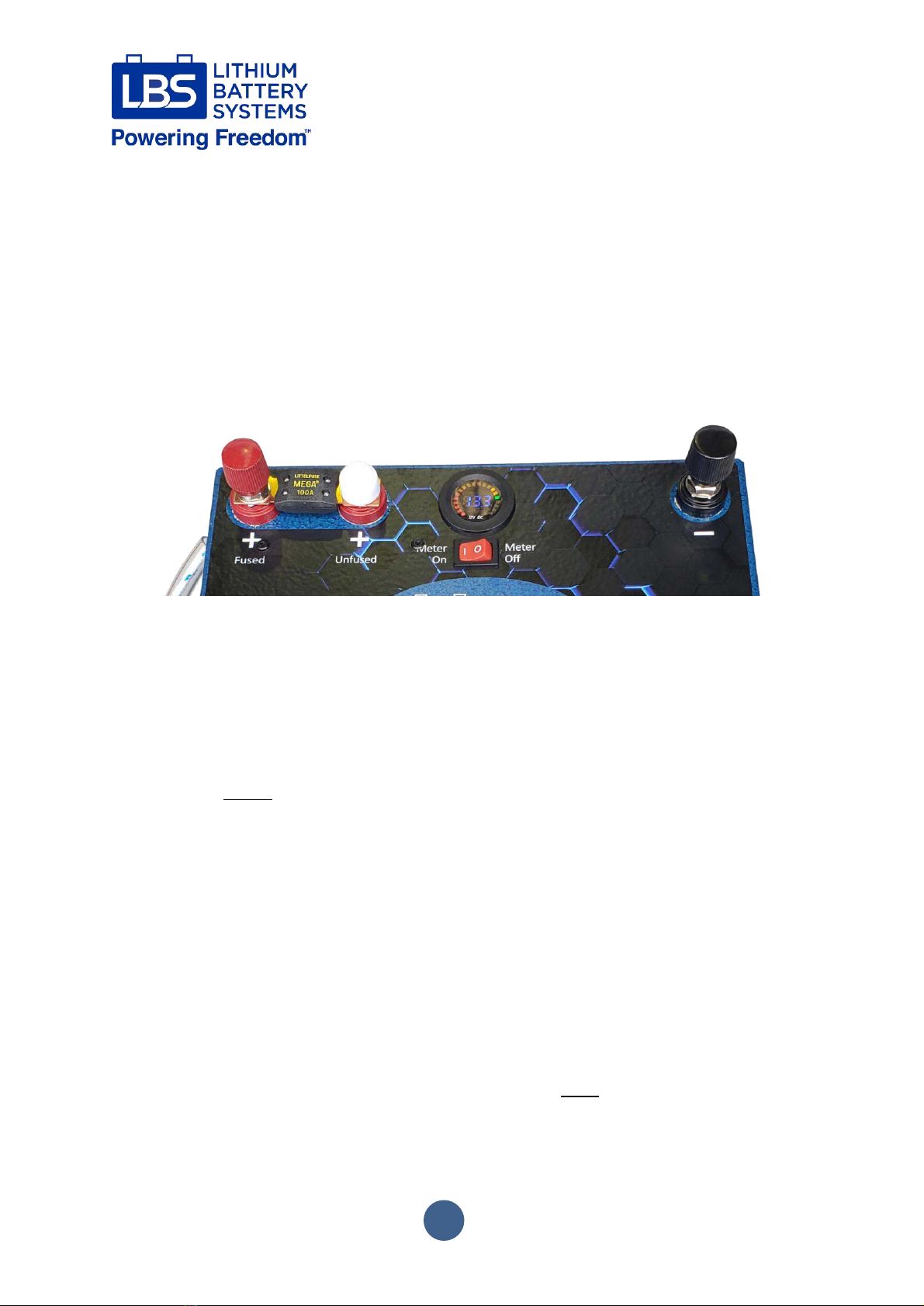
2.6 Do not short circuit the battery
Whilst the BMS will protect the internal cells from short circuit, it is highly recommended to avoid
short circuiting the battery. The MEGA Fuse on the external positive terminal of the battery also
provides over-current protection; if voltage is not present on the +Fused terminal, check for voltage
on the +Unfused terminal to check if the fuse has blown.
Pay attention when using metallic tools in the vicinity of the terminals, as accidentally contacting the
positive and negative terminal with a metallic object like a spanner will cause a short circuit and spark.
Always keep the plastic caps screwed on when not using the terminals.
Always perform work on passive wiring first and connect the live battery as the last connection. If you
have to work on live circuits exercise due care and use insulated tools where possible. If you are unsure
how to install the battery, seek advice from LBS or a suitably qualified electrical tradesperson.
2.7 Mounting orientation
The typical operating orientation is with the terminals facing upwards (except the 150C-SP-FT) and
should be the first option if possible. Having the battery terminals facing forwards is also an acceptable
orientation. The battery uses the aluminium lid as a heat sink, the function of which can be hampered
by an upside-down orientation; therefore, mounting upside down is not recommended. If in doubt
contact LBS or a suitable tradesperson for advice.