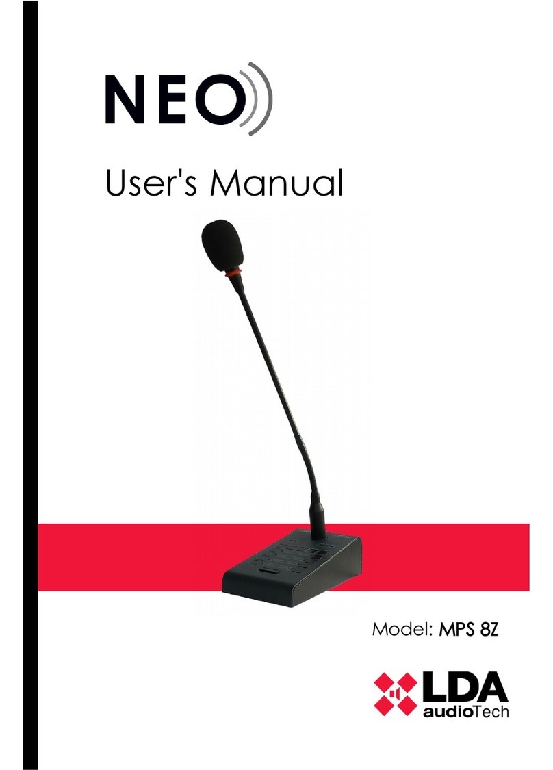
LDA Audio Tech MPS-8Z S02 User manual

Support Handbook
Connection to public address system with SIME
(MPS-8Z with ZES matrix)
Reference: LDA MPS-8Z S0

Connection to public address system with SIME (MPS-8Z with ZES22 matrix
Support Handbook - LDA MPS-8Z S02
1 INTRODUCION
This handbook shows the proper way to connect a public address microphone LDA MPS-8Z
system with SIM software, using the digital audio matrix Z S-22 S02.
1.1 Power supply
The MPS-8Z microphone is provided with a 5V dc USB connector external power supply,
which is connected via a miniUSB AB male to USB A male cable, also supplied. To power the
equipment you can use it, or power the equipment directly from the ACSI bus, through its
connection to the bus. At this case, save the power supply for use it later.
1.1.1 POWER SUPPLY SELECTION
MPS-8Z systems have a power supply DIP-
Swicth selector that allows to manage the
power source. You can switch between local
or ACSI bus power suply. When the switch
are set at OFF positions, that means it is
been supplied by local power source. At ON
position, the MPS-8Z will be supplied by
ACSI bus.
In case of both power supply sources were
connected, DIP-Switch must be set at ON
position (ACSI bus). This way, MPS-8Z will
have redundance and keep working even
ACSI bus goes down.
Picture 1: Microphone MPS-8Z, 5V power supply and UTP wiring connector.
Picture 2: Power selector for MPS-8Z

Connection to public address system with SIME (MPS-8Z with ZES22 matrix
Support Handbook - LDA MPS-8Z S02
1.2 RS-485 Connection
In order to properly connect MPS-8Z microhone and Z S-22, it is mandatory to do it by an
specific UTP cable. This cable should be CAT 5 or higher.
Starting with the attached diagram (Picture 3), the next connection must be followed
This will be the input connector for MPS8-Z Microphone (ACSI bus).
Next step, the wiring connection to Z S-22 must follow this pinout indicaions:
1. (Striped Orange): Audio +
2. (Orange): Audio -
3. (Striped Green): GND
4. (Blue): RS-4 5 A
5. (Striped Blue): RS-4 5 B
6. (Green): GND
7. (Striped red): + 24 V
. (Red): + 24 V
•This wiring must be connected by a three ways uroblock connector, getting split two
connector for RS-485 and audio input ports.
•As shows on Picture 4 indications, this wires connect to tags number 4 (input/output
Z S-22 ports) and number 8 (RS-485). Furthermore, the audio input CH3 must be the
used one for a correct setup.
Picture 3: RJ45 Type B pinout diagram

Connection to public address system with SIME (MPS-8Z with ZES22 matrix
Support Handbook - LDA MPS-8Z S02
That last configuration can be supplied with the LDAZ S22ACSIS01 adapter. As shows at
Picture 5, the RJ-45 conector allows the direct connection with the MPS-8Z microphone,
even bring it the power supply by a local 5V dc USB adapter.
1.3 Connecting severals MPS-8Z units
MPS-8Z systems counts with several PA elements. It consists of an audio input at line level
plus control signals, for connection of up to 8 devices in daisy chain bus mode, where each
device is connected to the next one. Both connections are identical and interconnected. This
connection must be made from the output of one microphone to the input of the next (as
shown in Figure 6, the OUT and IN connectors respectively).
Picture 4: Z S-22 ports diagram
Picture 5: LDA Z S-22 ACSI S01 adapter

Cnnection between MPS-8S units must be done by standar T568B ehernet cable. Maximum
connection distance for the entire bus 1000m (3280ft). In total, up to 8 MPS-8Z devices can
be connected to each Z S-22.
The ACSI bus does not provide power to the equipment remotely, so each MPS-8Z
microphone must have its own local source.
ach device has a priority selector inside the bus. Depending on the priority set, you will be
allowed to occupy the channel when it is occupied by another device. The priority of the
MPS 8Z matches the direction of the ACSI bus. To set the ACSI address of the MPS 8Z,
follow these steps:
•Make sure the team has no word granted. The "CW" indicator will be off.
•Press and hold the "CANC L" button and the "M M" button for at least 2 seconds.
•Access to the address setting will be confirmed by flashing the "LINK" and " MG"
indicators. The configured bus address will be indicated by lighting the associated zone
memory indicator.
•Press the memory selection button whose number corresponds to the desired
address. Remember that the address matches the priority. The corresponding zone
memory selection indicator will light up.
•Press the "TALK" button to confirm, "CANC L" to cancel the address change.
•The unit will restart with the new bus address.
In case of "LINK", "FAULT" and " MG" flash simultaneously when the MPS-8Z is started,
there is an address conflict on the ACSI bus with this device. In this case, the address must
be changed.
1.4 MPS-8Z Configuration
It is possible to configure MPS-8Z Paging Microphone according to several operation
parameters. To access the configuration mode of the device, follow these steps:
Picture 6: MPS-8Z ports

Connection to public address system with SIME (MPS-8Z with ZES22 matrix
Support Handbook - LDA MPS-8Z S02
◦Make sure the device does not have conceded word. The “CW” light should be off.
◦Keep pressed the button “CANC L” and the button “ V NT” for at least 2 seconds.
◦When you are in the configuration mode, the “FAULT” and “ MG” lights will be blinking.
◦Configure the parameters as shown as following.
◦Press the button “TALK” to confirm, or “CANC L” to cancel any change.
◦The device will restart with the new configuration.
1.4.1 CONFIGURATION. TALK
•The zone 1 button enables/disables the “latch” function for the “TALK” button. When
this option is enabled, the zone 1 light will remain on. When this function is enabled,
pressing once the “TALK” button will keep the microphone open until the “TALK”
button is pressed again.
•To confirm the new configuration, press “TALK”, to cancel, press “CANC L”.
1.4. CONFIGURATION. CHIME
•The zone 2 button enables/disables the pre-talk chime. When this function is enabled
(light on), a chime will be played before the microphone is open to talk.
•To confirm the new configuration, press “TALK”, to cancel, press “CANC L”.
1.4.3 CONFIGURATION. EXTERNAL MICROPHONE
•The zone 3 button enables/disables the input for an external microphone. When this
function is enabled (light on), the external microphone input will be enable and the
microphone incorporated within MPS-8Z will be disabled.
•To confirm the new configuration, press “TALK”, to cancel, press “CANC L”.
1.4.4 CONFIGURATION. DSA
•The zone 4 button enables/disables the DSA function. DSA (Digital Sound Adjustment)
is a Digital Voice Processing that automatically adjust the gain of the voices of different
users. When this function is enabled, the zone 4 light will remain on.
•To confirm the new configuration, press “TALK”, to cancel, press “CANC L”.
1.4.5 CONFIGURATION. LOCK
•The zone 5 button enables/disables the keyboard lock. When this function is enabled
(light on), the MPS-8Z will be automatically locked after 1 minute since the last
operation on the microphone. In order to unlock the microphone, you will need to
press the buttons “CANC L” and “TALK” simultaneously.
•To confirm the new configuration, press “TALK”, to cancel, press “CANC L”.

1.4.6 CONFIGURATION. OUTPUT VOLUME
•The output volume level of the MPS-8Z is configured with Zone 7 and Zone 8 buttons.
Press Zone 7 to increase the volume level and Zone 8 to decrease volume level. ach
time the button is pressed, the corresponding zone light will be shortly on. When the
volume level is at the maximum, the zone 7 light will remain on. When the volume
level is at the minimum, the zone 8 light will remain on.
•To confirm the new configuration, press “TALK”, to cancel, press “CANC L”.
SYSTEM REQUERIMENTS
•Z S-22 firmware 1.0.5 or higher
•Z S-22 Setup versión 4.1 or higher.
•To allow audio input to channel 3 of the Z S-22 matrix, it must be configured as 3
inputs and one output (3x1) four inputs (4x0). This configuration can be set using the
Z S-22 Setup software.
For more information, please, contact with our Support Department at:
Table of contents
Other LDA Audio Tech Microphone manuals
Popular Microphone manuals by other brands

Kenwood
Kenwood KCH-16 Service manual

Audio Engineering Associates
Audio Engineering Associates R88 user manual
RODE Microphones
RODE Microphones STEREO VIDEOMIC PRO instruction manual
Motorola solutions
Motorola solutions PMMN4128 quick start guide
Steren
Steren ktv-060 quick start guide
Electro-Voice
Electro-Voice Aviation 903E Specification sheet
