Le-Tehnika 4Ports+Wireless User manual

User Manual
4Ports+Wireless
User Manual

User Manual
Important Safety Instructions
Please read these instructions carefully:
1. Unplug the ADSL2+ Router Ethernet Adaptor from the wall outlet before
cleaning. Do not useliquidcleaners or aerosol cleaners. Usea damp cloth
for cleaning.
2. Do not use the ADSL2+ Router Ethernet Adaptor near water.
3. Make sure the working platform is flat. Do not put heavy objects on the
ADSL2+Router.
4. Use the AC/DC power adapter that matches the ADSL2+ Router.
5. Disconnect the power supply and all wires from the ADSL2+ Router in
lightning storm, to avoid lightning strike.
6. Take water proof measures during the storage, transportationand running
of the ADSL2+ Router.
7. Avoid direct sunlight.
Note: When the ADSL2+ Router is used for a long time, temperature of the
shell will rise. This is normal.

User Manual
Table of Contents
Chapter 1 Overview....................................................................1-1
1.1 System Features.............................................................1-1
1.2 Supporting protocols .......................................................1-1
1.3 Encapsulation supports...................................................1-2
1.4 System requirements ......................................................1-2
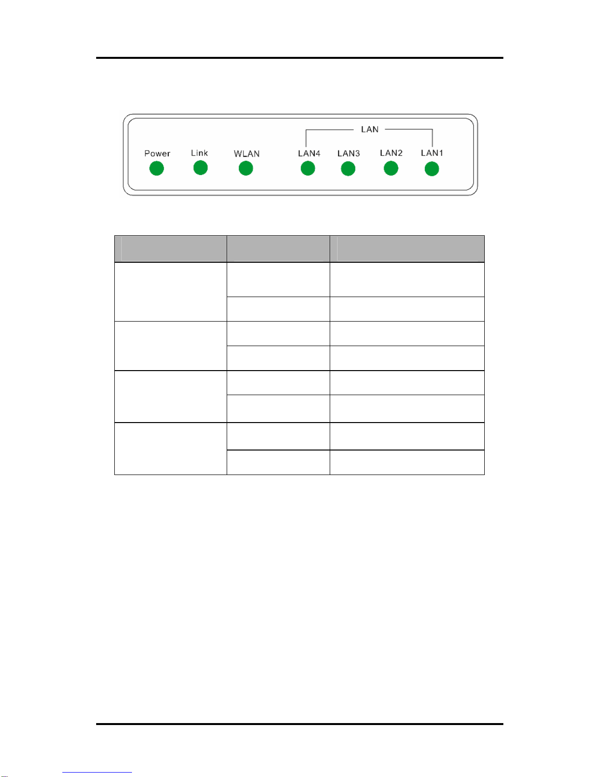
1.5 LED Status Description ...................................................1-3
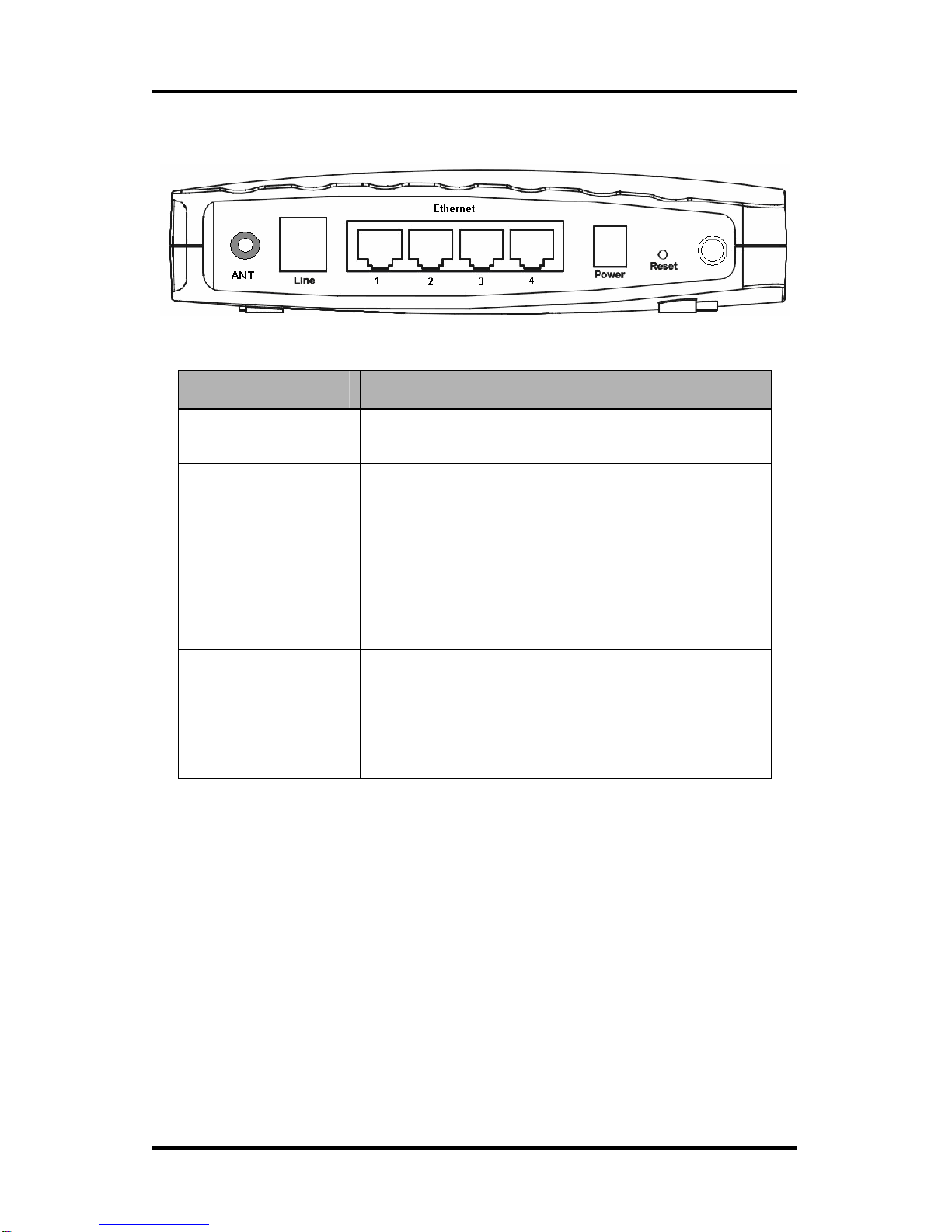
1.6 Rear Panel Layout Description........................................1-4
Chapter 2 Installation.................................................................2-1
2.1 ADSL2+ MODEM Installation ..........................................2-1
Chapter 3 Configuration.............................................................3-1
3.1 Configuring computer network card IP address................3-1
3.2 Web setting interface.......................................................3-1
3.3 Main interface .................................................................3-2
3.4 SETUP............................................................................3-2
3.4.1 WAN Configuration ...............................................3-3
3.4.1.1 Configuring PPPoE............................................3-4
3.4.1.2 Configuring PPPoA............................................3-6
3.5 ADVANCED..................................................................3-10
3.5.1 Advanced the main page.....................................3-10
3.5.2 Configuring QoS .................................................3-11
3.6 WIRELESS...................................................................3-14
3.6.1 Wireless main page.............................................3-14
3.6.2 Wireless Setup....................................................3-14
3.6.3 Wireless Configuration........................................3-16

User Manual
3.6.4 Wireless Security................................................3-17
3.7 TOOLS .........................................................................3-21
3.7.1 Tools main page .................................................3-21
3.7.2 Update Gateway .................................................3-21
Chapter 4 Questions & Answers................................................4-1

User Manual
Page 1-1
Chapter 1 Overview
Thank you for purchase of the ADSL2+ Router device. This device is a
well-designed high-speed wireless ADSL2+ Router. This User Manual will
show you how to install and set up the ADSL2+ Router.
1.1 System Features
TheADSL2+ Router provides the following functions:
zFour 10/100 Ethernet ports
zFriendly GUI for web configuration
zSupport Single-Session IPSec and PPTP Pass-Through for Virtual
Private Network (VPN)
zSeveral popular games are already pre-configured. Just enable the
game and the port settings are automatically configured
zConfigurable as a DHCP Server on Your Network
zCompatible with virtually all standard Internet applications
zIndustry standard and interoperable DSL interface
zAddress Filtering, DMZ Hosting, and Much More
zSimple web based status page displays a snapshot of your system
configuration, and links to the configuration pages
zDownloadable flash software upgrades
zSupport for up to 8 Permanent Virtual Circuits (PVC)
zSupport for up to 8 PPPoE sessions
1.2 Supporting protocols
zITU G.992.1 (G.DMT) Annex A
zITU G.992.2 (G.LITE)
zANSI T1.413 Issue 2
zITU G.992.3 (ADSL2)
zITU G.992.5 (ADSL2+)

User Manual
Page 1-2
1.3 Encapsulation supports
zRFC 1483 bridge
zRFC 1483 router
zClassical IP over ATM (RFC 1577)
zPPP over ATM (RFC 2364)
zPPP over Ethernet (RFC 2516)
1.4 System requirements
Recommended system requirements are:
zPentium 233MHZ or above
zMemory: 64MB or above
z10M Base-T Ethernet or above
zWIN9XWIN2000WINXPWINMEWINNT
zEthernet Network Interface Card
Please collect the following information from your ADSL2+ service provider.
This information will be very helpful for your ADSL2+ configuration. To keep a
record for reference, you can fill in the column as below:
VPI
VCI
Encapsulation: VCMUX or LLC
Protocol
Standard
User name
Password
Password protocol

User Manual
Page 1-3
1.5 LED Status Description
Indicator Status Description
OFF Power not supplied
Power ON Power supplied
Blink DSL traffic is flowing
Link Quick Blink DSLline is training
Quick Blink DSLline is training
WLAN ON DSL line is connected
ON Ethernet line is connected
LAN
(1-4) Blink Ethernet traffic is flowing

User Manual
Page 1-4
1.6 Rear Panel Layout Description
Interface Description
Switch Power on/off switch
Reset
Modem Reset button .Press and hold around
10s to reset the hardware. Modem’s LED will be
all onthen all off except thePower LED, andthe
modem will auto restart. This action will recover
the modem’s default configuration.
Power socket Plug in for power adaptor
LAN(1~4) LAN interface for connecting to computer or
Switch
Line ADSL2+ connector for connecting to ADSL2+
telephone line

User Manual
Page 2-1
Chapter 2 Installation
2.1 ADSL2+ MODEM Installation
Please connect your ADSL2+ Router to computer as the following description:
If connecting to the splitter,
zConnect the “Line” splitter to wall jack using one telephone cable
zUse the other telephone cable to connect “MODEM” port of the
splitter and “LINE” port of the modem. The “phone” port of the
splitter can be use to connect the telephone and the splitter by a
telephone cable.
zUse Ethernet cable to connect “LAN” port of the modem and “LAN”
port of your computer.
If do not need to connect to the splitter,
zConnect the modem to wall jack using one telephone cable
zPlease use the Ethernet cable to connect the Ethernet port of
the modem and LAN port of your computer.

User Manual
Page 3-1
Chapter 3 Configuration
3.1 Configuring computer network card IP address
Configure your network card’s TCP/IP properties to Obtain an IP address
automatically from modem, or set the computer’s IP with the same network
mask of the modem.(For example: modem’s IP is 192.168.1.1/255.255.255.0,
Then you can set computer’s IP to:
192.168.1.x/255.255.255.0.
The range for x is from 3 to 254).
3.2 Web setting interface
Open IE or Netscape Web browser, Input http://192.168.1.1(MODEM default
IP address) in the address column, then click <ENTER> button, access the
following setting interface:
Input user name and password, then click Login key to enter WEB setting
interface.
Default setting:

User Manual
Page 3-2
IP Address: 192.168.1.1
Subnet Mask: 255.255.255.0
Username: admin
Password: admin
3.3 Main interface
When correct username/password has been typed, the following WINDOW will
pop up:
You can realize operating as follows though the home page:
zRG configuration (though the connection between the LAN and the
WAN)
zAdvanced of RG configuration (security, router, filter act)
zObtain the state of RG
zLook over help
Note—RG:Residential Gateway, refer to Modem itself here.
3.4 SETUP
This chapter introduces the configuration of the ADSL2+ Modem through Web,
including the following contents:

User Manual
Page 3-3
zLAN Setup
The local host’s computers connect to LAN interface, generally set up and
assign IP address in LAN the host computers of ends automatically.
zWAN Setup
Mainly set up WAN to dispose.
3.4.1 WAN Configuration
The RG supports and sets up to 8 different connections, if you set up many
different connections, then you need to use the static behavior of RG and
dynamic route function to make data transmission correct.
Before setting up new WAN to connect, should confirm that you connect to
DSL first, there is an indicator lamp by Modem chaining, green color
specification was connected to DSL, red color specification has not been
connected to.
6 kinds of different kinds of connections in all are offered to users, including:
PPPoE, PPPoA, Static, DHCP, Bridge, and CLIP. Now introduce their use one
by one for everybody.

User Manual
Page 3-4
3.4.1.1 Configuring PPPoE
Follow the steps listed below to configure:
1. Click the “New Connection”, PPPoE that will demonstrate default
connection pages.
2. Enter the Username, generally the naming rule as" type + PVC", such as
PPPoE_8_35.
3. NAT and Firewall select default as the state of choosing.
Note—NAT can change IP address of LAN end into IP address of WAN
end, if does not choose NAT to select, can not surf the Net.
4. If you want to use VLAN, draw the frame to choose VLAN under sharing,
can edit the state while making VLAN id AND Priority Bits area in , inputs
ID of VLAN in VLAN ID place, rank that in Priority Bits to choose to have
priority for VLAN.
5. Input your DSL service provider or data of ISP provide in PPP setting area
in, such as username and password.
6. Input VPI and VCI in PVCsetting area in. The VPI/VCI was offered by ISP
of your DSL service provider.
7. Choose QoS. If you uncertain ISP offers such information, uses default

User Manual
Page 3-5
finally.
8. Click “Apply” to finish the connection .As follow:
9. In order to keep setting up, click TOOLS of the page above, then choose
System Commands, click SaveAll button to keep.
10. Click “STATUS” of the page above; choose Connection Status to check
the connection state. As following:

User Manual
Page 3-6
3.4.1.2 Configuring PPPoA
Follow the steps listed below to configure:
1. Click the “New Connection”, PPPoA that will demonstrate default
connection pages.
2. Choose the PPPoA in the frame of drawing under the Type.
3. Enter the Username, generally the naming rule as “type + PVC ", such as
PPPoA_0_100.
4. NAT and Firewall select default as the state of choosing.

User Manual
Page 3-7
Note—NAT can change IP address of LAN end into IP address of WAN
end, if does not choose NAT to select, can not surf the Net.
5. If you want to use VLAN, draw the frame to choose VLAN under sharing,
can edit the state while making VLAN id AND Priority Bits area in , inputs
ID of VLAN in VLAN ID place, rank that in Priority Bits to choose to have
priority for VLAN.
6. Choose encapsulation type: LLC or VC in PPP setting area in. If don’t
confirm, use the default. Then enter your Username and Password.
7. Input VPI/VCI in PVC setting area in. The VPI/VCI was offered by your
DSL service provider and ISP service provider.
8. Choose the QoS.
9. Click the “Apply” to finish the connection. As following:
10. Remember to keep and set up, otherwise all modificationislost after RG is
opened again next time. Go to System Commands page in TOOLS page,
click SaveAll.
11. Click“STATUS” ofthe pageabove; choose “Connection Status” can check
the connection state.

User Manual
Page 3-8
3.4.1.2 Configuring Bridge
Following the steps listed below to configure:
1. Click the “New Connection,”PPPoE that will demonstrate default
connection pages.
2. Choose Bridge in the frame of drawing under the Type, will show that
Bridge connection pages.
3. Enter the Username, generally the naming rule as “type + PVC”, such
as Bridge_8_35.
4. Choose encapsulation type: LLC or VC in Bridge setting area in. If
don’t confirm, use the default.
5. Input VPI/VCI in PVC setting area in.
6. Choose QoS.
7. Click “Apply” to finish the connection.

User Manual
Page 3-9
8. Remember to keep and set up, otherwise all modification is lost after
RG is opened again next time. Go to System Commands page in
TOOLS page, click SaveAll.
9. Click “STATUS” of the page above; choose Connection Status can
check the connection.

User Manual
Page 3-10
3.5 ADVANCED
3.5.1 Advanced the main page
Use the advanced page; you can dispose the connection that has already
existed advanced. Include:
zUse UPNP, SNTP, IP, QoS, RIP, access control, broadcast the
function
zIn order to connect which assigns IP QoS
zManage the interface of LAN, dataflow and filtering
Must set up a WAN at least to connect before carrying out WAN to configure
advanced, must define one LAN group at least before carrying out LAN to
configure advanced.

User Manual
Page 3-11
3.5.2 Configuring QoS
Quality of service (QoS) is an important feature for this release. The QoS
Framework allows network administrators to configure the routers to meet the
real time requirements for voice and video.
Different QoS marking is used in different network:
z ToS network: ToS bits in the IP header
z VLAN network: Priority bits in the VLAN header
z DSCP network: Uses only 5 bits of the CoS
z WLAN: WLAN QoS header
The QoS framework is supported on all the above domains. How do you make
them talk to each other? How can you make sure the priority from one network
is carried over to another network? Class of service (CoS) is introduced as the
common language for the QoS mappings. When QoS is enabled, the RG has
full control over packets from the time they enter the RG till they leave the RG.
This is how it works: The domain mapping (ToS bits, priority bits, etc.) of a
packet needs to be translated to CoS when the packet enter the RG, and vice
versa, the CoS of a packet needs to be translated back to thedomainmapping
when the packet leaves the RG.
CoS: There are 6 types of CoS (in descending priority):
Table of contents