Leader Evaporator Springtech EXTREME 6 User manual

Leader Evaporator Co., Inc.
49 Jonergin Drive
Swanton, VT 05488
Tel: 802-868-5444
www.leaderevaporator.com
EXTREME 6
Reverse Osmosis System

LeaderEvaporatorSpringtechEXTREME6ReverseOsmosisSystemManual Page:2
TABLEOFCONTENTS
INTRODUCTION..........................................................................................................................................................................4
THEORYOFOPERATION..............................................................................................................................................................4
Terms..............................................................................................................................................................................................4
DescriptionofMembrane...............................................................................................................................................................5
EQUIPMENTDESCRIPTION..........................................................................................................................................................6
FRONTVIEW...........................................................................................................................................................................................6
REARVIEW.............................................................................................................................................................................................6
FEEDPUMP............................................................................................................................................................................................7
PRESSUREPUMP.....................................................................................................................................................................................7
RECIRCULATIONPUMPS............................................................................................................................................................................7
CONTROLPANEL.....................................................................................................................................................................................8
FLOWMETERS........................................................................................................................................................................................8
PRESSUREGAUGES..................................................................................................................................................................................8
SAMPLINGPORTS....................................................................................................................................................................................9
V1ANDV2VALVES.................................................................................................................................................................................9
FLOWCONTROLVALVES...........................................................................................................................................................................9
INCLUDEDEQUIPMENT...........................................................................................................................................................................10
OPTIONALSETUPEQUIPMENT,PARTSANDSUPPLIES....................................................................................................................................11
SETUP.......................................................................................................................................................................................12
AREAREQUIRED....................................................................................................................................................................................12
POWERREQUIREMENTS..........................................................................................................................................................................12
GENERALCONNECTIONLAYOUT...............................................................................................................................................................13
Simple3TankRODiagram...........................................................................................................................................................13
STRAINERTOVALVEV6CONNECTION.......................................................................................................................................................14
VESSEL,PUMP,PREFILTERCANISTERANDWASHTANKDRAINS....................................................................................................................14
V3,V4ANDV19CONNECTIONS..............................................................................................................................................................17
V19–ConnectionToDrain...........................................................................................................................................................17
V3–ConnectionToPermeateStorage.........................................................................................................................................17
V4–ConnectiontotheConcentrateStorage...............................................................................................................................18
OPERATION..............................................................................................................................................................................19
STARTUPOFSYSTEMWITHLITTLEORNOFLUID...........................................................................................................................................19
INITIALSYSTEMCLEANING.......................................................................................................................................................................20
DATALOGGING.....................................................................................................................................................................................20
CYCLESANDTIMING...............................................................................................................................................................................21
PERMEABILITYTEST................................................................................................................................................................................22
FLOWVALVEINFORMATION....................................................................................................................................................................25
ADJUSTINGV1ANDV2FOROPERATIONS..................................................................................................................................................26
SAMPLEPORTUSE.................................................................................................................................................................................26
CONCENTRATECYCLE.............................................................................................................................................................................26
DESUGARCYCLE....................................................................................................................................................................................29
RINSECYCLE.........................................................................................................................................................................................31
WASHCYCLE........................................................................................................................................................................................34
HotWaterWash...........................................................................................................................................................................34
AlkalineSoapWash......................................................................................................................................................................34
AcidSoak......................................................................................................................................................................................34
MAINTENANCE.........................................................................................................................................................................37

LeaderEvaporatorSpringtechEXTREME6ReverseOsmosisSystemManual Page:3
PREFILTERS...........................................................................................................................................................................................37
MEMBRANEREMOVALANDINSTALLATION.................................................................................................................................................39
Removal........................................................................................................................................................................................39
→CommonStepsforRemovalofMembranes.............................................................................................................................................39
→StepsforRemovalOfBrineSealClampedMembranes............................................................................................................................41
→StepsforRemovalOfThreadedRodClampedMembranes......................................................................................................................42
Installation...................................................................................................................................................................................43
→StepsforInstallaonofBrineSealClampedMembranes.........................................................................................................................43
→StepsForInstallaonofThreadedRodClampedMembranes..................................................................................................................45
CommonStepsforInstallation.....................................................................................................................................................................47
DAILY..................................................................................................................................................................................................48
PERIODIC.............................................................................................................................................................................................49
ENDOFSEASONSHUTDOWNANDSTORAGE...............................................................................................................................................49
BEGINNINGOFSEASONSTARTUP..............................................................................................................................................................51
TROUBLESHOOTINGCHART......................................................................................................................................................53
ATTACHMENT#1–ELECTRICALSCHEMATIC..............................................................................................................................54
ATTACHMENT#2–OPERATIONSDATALOGSHEET....................................................................................................................56
ATTACHMENT#3‐PERMEABILITYTESTSHEET..........................................................................................................................57
ATTACHMENT#4–WARRANTYINFORMATION.........................................................................................................................58

LeaderEvaporatorSpringtechEXTREME6ReverseOsmosisSystemManual Page:4
INTRODUCTION
ALeaderEvaporatorSpringtechEXTREMEReverseOsmosissystemisdesignedtosignificantlyimprovetheproducer’s
productivitybygeneratinghighsugarpercentagesap.Throughuseofhighpressure,thesystemremoveswaterfrom
thesapresultinginamoreconcentratedsugarsolutionenteringtheevaporator.Thisinturnshortenstheboiltime
requiredresultinginfuelandtimesavings.
SomeofthefeaturesoftheSpringtechEXTREME6are:
Easyaccessibilitytopumpsandmembranes
Stainlesssteelframe,membranehousings,pumpsandpumphousings
Fastwashcycle
Withreasonablesap–theabilitytogeneratehighbrixconcentratewithasinglepass
Flowmetersforthepermeateofeachvesselandoneforthesystemconcentrate
THEORYOFOPERATION
Inreverseosmosis,throughtheuseofspecialsemi‐permeablemembranesandhighpressure,waterisforced,ina
pureform,throughthemembranewhiletheconcentratedsolutionremainsoutsidethemembraneandis
concentrated.Forthesugarmakerthismeanswater(permeate)isremovedfromthesapandasapwithahigher
sugarlevel(concentrate)isproducedfortheevaporationprocess.
Terms
Semi‐permeableMembrane–Unitconsistingofmultilayersofspacersandmembranes
Pre‐FilterUnit–Designedtoremovesuspendedsolidsfromthesapincomingtothereverseosmosissystem
FeedPump–Theinitialpumpdesignedtosupplythereverseosmosisunitwithsapandmaintainpressurein
thesystem
PressurePump–Thepumpdesignedtoprovidethepressureneededtoforcethesapthroughthereverse
osmosismembrane
PressureVessel–Thecontainmentunitforthesemi‐permeablemembrane
Permeate–Purifiedwaterremovedfromthemaplesapduringtheconcentratecycle
Concentrate–themaplesaphavingahigherpercentageofsugarbecausewater(permeate)hasbeen
removed
PermeateHoldingTank–Atankdesignedtoholdaminimumtwicethehourlyoutputofthesystem
ConcentrateCycle–ProcessduringwhichwaterisremovedfrommaplesapresultinginConcentrateand
Permeate
ReverseFlowConcentrateCycle–Concentratecycleinwhichtheflowthroughthesystemisreversed
allowingmoreevenuseofthemembranes
De‐SugaringCycle‐ProcesstoreclaimsugarsfromthemembraneduringwhichPermeateisrunthrough
thereverseosmosisunitusingConcentratecyclevalvesettings
RinseCycle–CleaningprocessofpassingstoredPermeatethroughtheReverseOsmosissystemandout
todrain
ChemicalWashCycle–Processofchemicalwashingthemembranesbyrecirculatingasolutionthrough
thereverseosmosissystem.Dependentonrequirement,chemicalmaybebealkalioracid.
PermeabilityTest–Testtodeterminetheperformanceofthemembranesagainstabenchmark
SapRecirculationLoop–Processofrecirculatingoutputfromtheconcentratecycletotherawsaptank,
increasingtheconcentrationofthesapinthetank
LeaderEvaporatorSpringtechEXTREME6ReverseOsmosisSystemManual Page:5
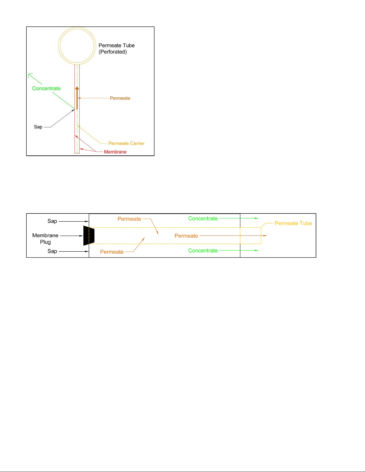
DescriptionofMembrane
Thedrawingaboverepresentstheflowofliquidthroughamembraneinthesystem.Themembraneishoused
inapressurevessel(notshown).
Thebasicunitsofthereverseosmosismembraneare
describedinthecrosssectiondrawing.
Attachedtothepermeatetubeisamembraneunit
consistingofapermeatecarrierbetweentwo
membranes.
Thereareanumberofthesemembraneunitsattached
aroundtheoutsideofthepermeatetube.
Betweeneachofthemembraneunitsisaspacer
throughwhichthesapandconcentratecanflow.
Thepermeatetubeisperforatedsothepermeatecan
becollectedfromthemembraneunit.
Ateachunitasthesapispressurized,thepermeate
canflowthroughthemembraneandbecarriedtothe
permeatetube.Theconcentratecannotpenetratethe
membraneandispushedoutthemembraneassembly.
Themembraneunitsarewoundaroundthepermeate
tubeandanoutsidesupportstructureisplacedaround
thewoundassembly.
LeaderEvaporatorSpringtechEXTREME6ReverseOsmosisSystemManual Page:6
EQUIPMENTDESCRIPTION
TheLEADEREVAPORATORSpringtechEXTREMEReverseOsmosisSystemisdesignedtooffermaximumconcentration
tocostperformance.Throughoptimizingofpumpsandmembranesthereverseosmosissystemsdelivergreaterflow
potentialtotheuser.TheLEADEREVAPORATORSpringtechEXTREMEReverseOsmosissystemisdesignedandbuilt
usingthesameprinciplesofsuperiorqualityappliedtoourevaporators.
TheLEADEREVAPORATORSpringtechEXTREMEReverseOsmosisSystemiscoveredbyamanufacturer’swarranty–
SeeATTACHMENT#4.
NOTES:
1. Pictures,sketchesanddrawingspresentedinthisdocumentarenottoscale.
2. Directions(rightandleft)willbeasfacingthefrontofthesystem.
3. Thefeedpump,prefiltersandwashtankaremountedasaseparateunittobeattachedtothemainsystem.
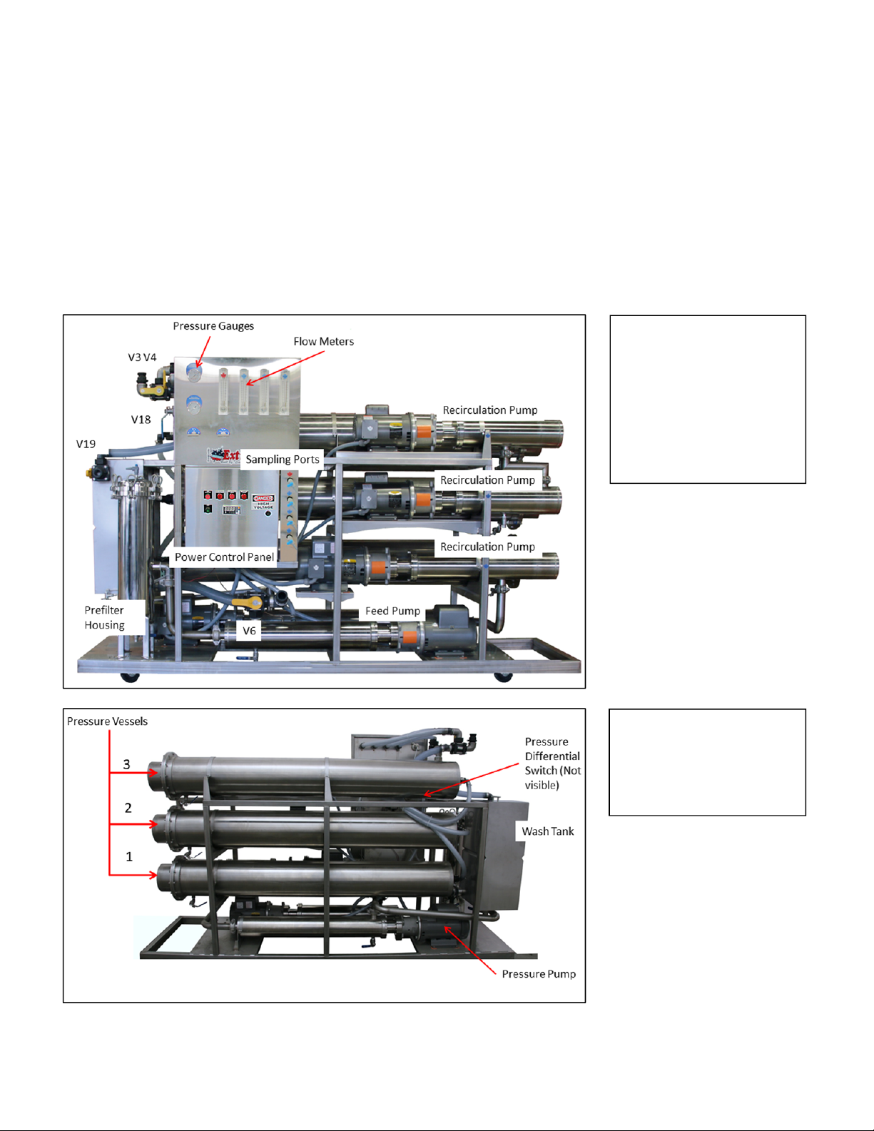
FrontView
Prefilterhousingrequires
five(5)–20”cartridge
filters.
RearView
Washtankisusedtomix
thechemicalsolutionfor
cleaningthesystem
LeaderEvaporatorSpringtechEXTREME6ReverseOsmosisSystemManual Page:7
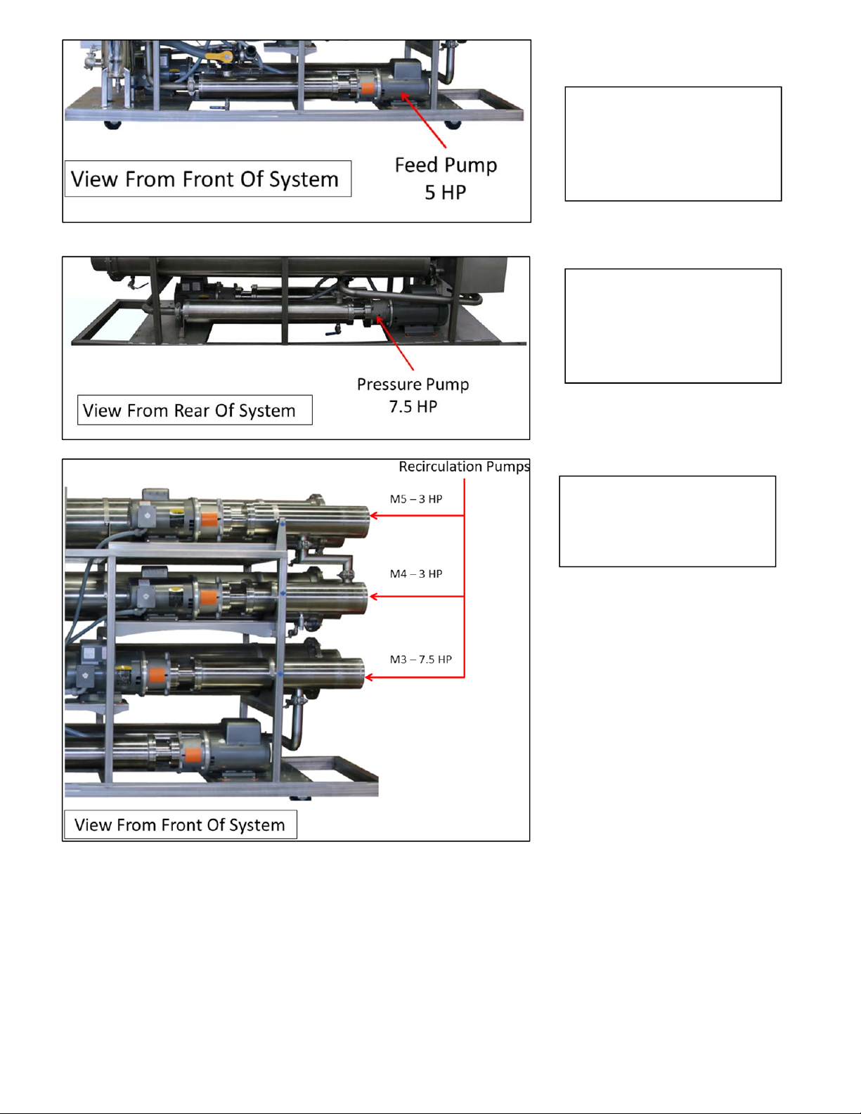
PressurePump
Secondstageofpressurizingthe
systemrequiredtoprocessthe
sapthroughthemembranes
RecirculationPumps
Recirculatesliquidwithinthe
vesseltowhichtheyareattached.
FeedPump
FeedPumpprovidesliquidtothe
systemandisthefirststageof
pressurizingthesystem
LeaderEvaporatorSpringtechEXTREME6ReverseOsmosisSystemManual Page:8
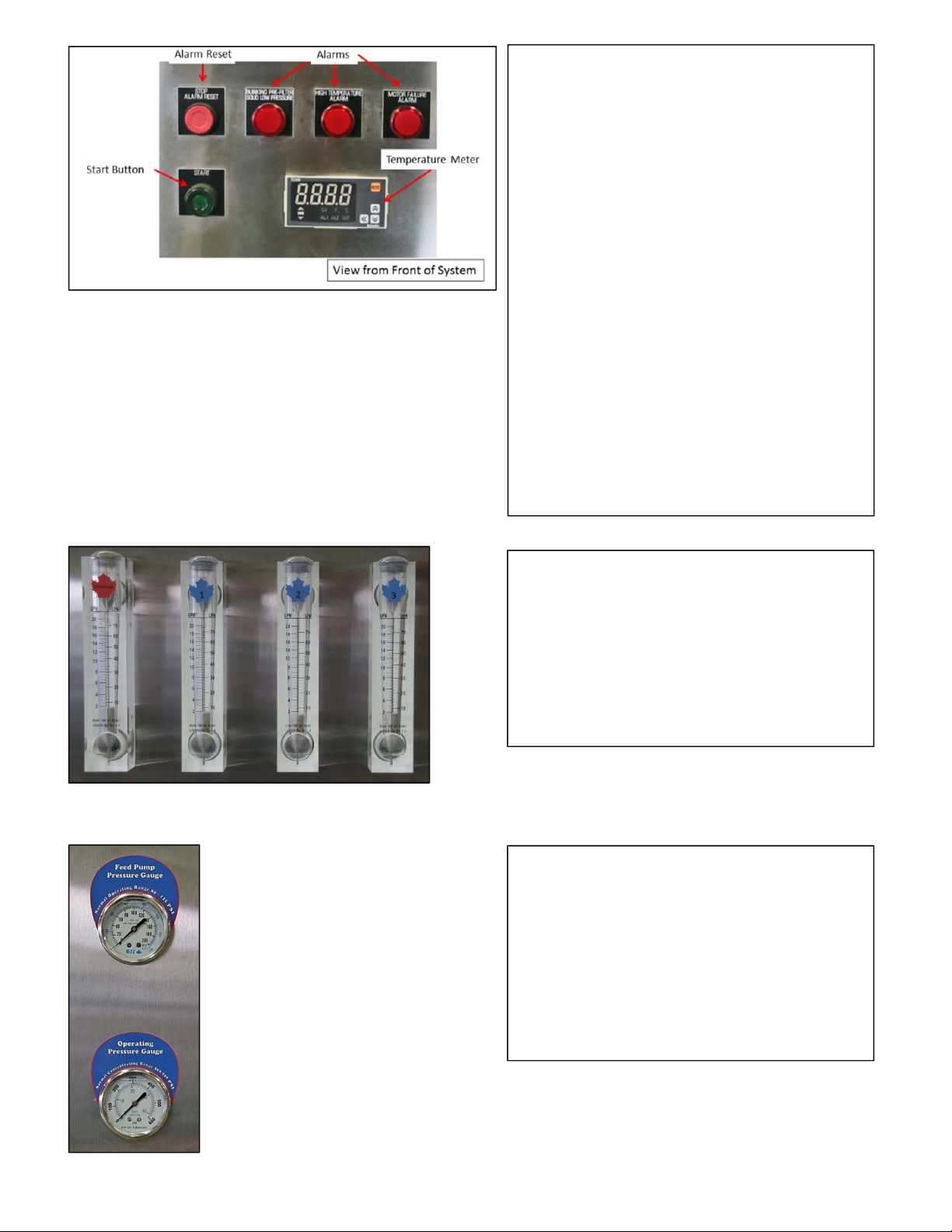
ControlPanel
Startbuttonwhenpressedstartsthesystempumpsin
sequence.
TheSTOPorSTOP/ALARMRESETbuttonisamaster
resetforallthealarmsandwillstopthemachine
whenpressed.
TheTemperatureMeterindicatesthetemperatureof
theliquidflowingthroughthesystem.
PressureAlarmindicatesapressureconditioninthe
systemrelatedtothepressurepumprequirements.
Thealarmlightmaybesolid(lowpressure)orblinking
(prefilter).Thisalarmcanbepartofnormal
operations.Themachinewillshutdownwhenthe
indicatorlightisactivated.
HighTemperatureAlarmindicatestheWashcyclehas
completed.Thisalarmispartofnormaloperations.
Themachinewillshutdownwhenthealarmlightis
on.
MotorFailureAlarmisdueamotorcontactor
tripping.ContactLeaderEvaporator.
FlowMeters
TheConcentrateMeterindicatestheliquidflowfrom
theconcentratesideofthepressurevesselsingallons
perminute.
ThePermeateMetersindicatethepermeateflow
fromeachvesselingallonsperminute.
PressureGauges
Feedpumppressureisreadaftertheprefilters.
Membranepressureisreadafterthelast
membrane.
WARNING:DONOTALLOWTHEOPERATING
PRESSURETOEXCEED550psi.
LeaderEvaporatorSpringtechEXTREME6ReverseOsmosisSystemManual Page:9
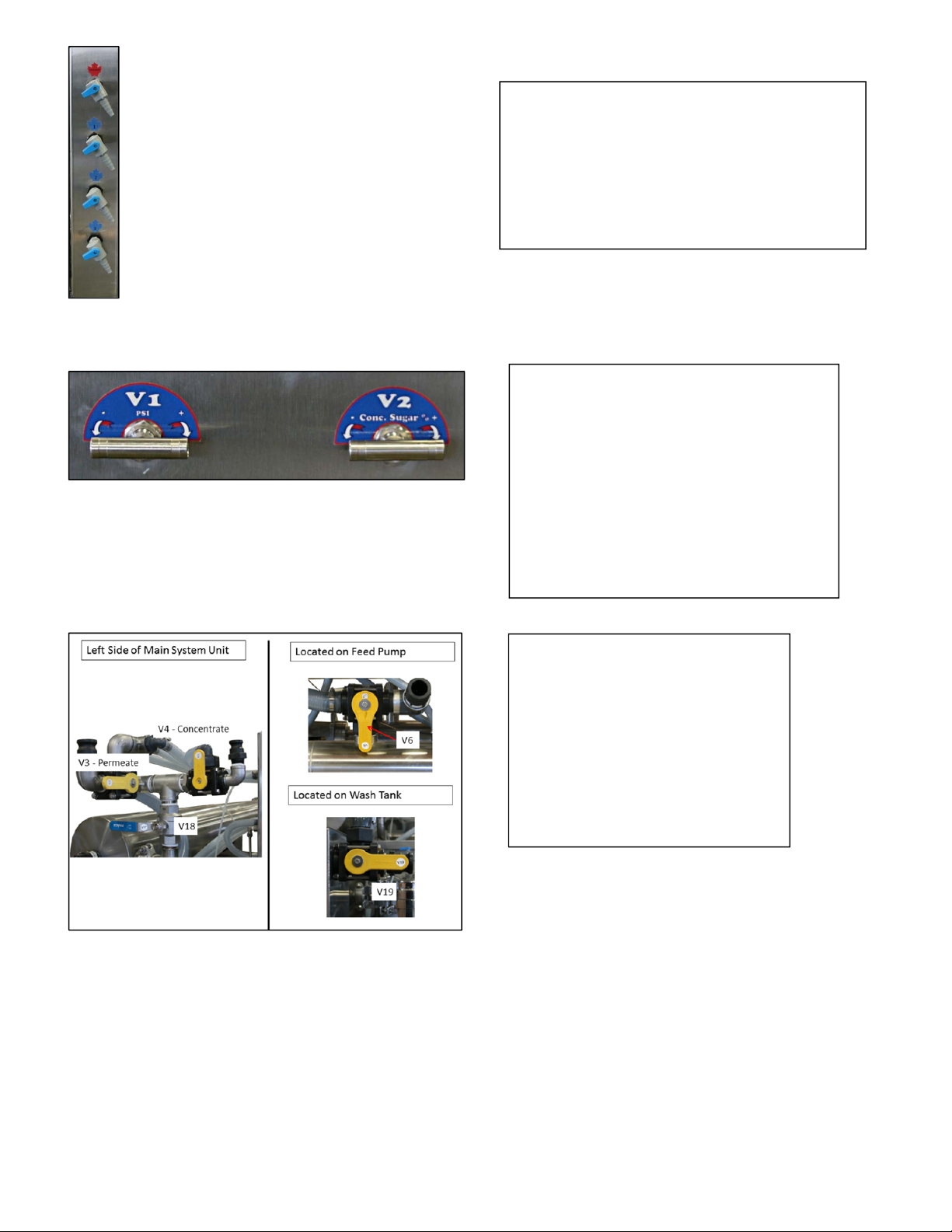
SamplingPorts
Concentrateportisusedtosampletheliquid
concentratetodeterminethesugarpercentage.
ThePermeateportsareusedtosamplethepermeate
fromthevesselstodetermineifthemembranesare
allowingsugartopassthrough.
V1andV2Valves
V1controlsthepressuretothemembranes.It
isopened½waywhenstartingthenadjustedto
reachthepressurewanted.CloseV1toraise
thepressureinthesystem.
V2controlstheflowfromtheconcentrateside
ofthemembranes.Itisopened½waywhen
startingthenadjustedtothedesired
concentrationlevel.
FlowControlValves
Thesevalvescontroltheflowofliquid
throughthesystem
V3–Permeateflow
V4–Concentrateflow
V6–Feedflow
V18–CleaningorConcentrateflow
V19–DrainorWashTank

LeaderEvaporatorSpringtechEXTREME6ReverseOsmosisSystemManual Page:10
VALVETYPE
HANDLE
POSITIONLIQUIDFROM‐TO
HANDLE
POSITIONLIQUIDFROM‐TO
V33‐Way
HANDLE
POINTED
HORIZONTAL
MembranestoPermeate
out
HANDLE
POINTED
VERTICAL
MembranestoValve
V19
V43‐Way
HANDLE
POINTED
VERTICAL
MembranestoConcentrate
out
HANDLE
POINTED
HORIZONTAL
MembranestoValve
V19
V63‐WayHANDLE
VERTICALExternaltoFeedPump
HANDLE
HORIZONTAL
WashTanktoFeed
Pump
V182‐Way
HANDLE
POINTED
HORIZONTAL
NoFlow
HANDLE
POINTED
DOWN
MembranestoValve
V19
V193‐Way
HANDLE
POINTED
HORIZONTAL
MembranestoWashTank
HANDLE
POINTING
VERTICAL
MembranestoDrain
TheLeaderSpringtechEXTREMEReverseOsmosissystemconsistsofthefollowingparts:
IncludedEquipment
ITEMLEADER
ORDER#DESCRIPTION/PHOTOITEMLEADER
ORDER#DESCRIPTION/PHOTO
Springtech
EXTREME6
700068
Springtech
EXTREME6User
Manual
Springtech
EXTREME6
QuickStart
Guide
1–1/2”Quick
CouplerC
Qty:2
47160
1”Quick
CouplerC
Qty:1
47148
2”Threadedto
3”Slip
Connector
195
StrainerY
3”modified
withbleeder
valve
70141
LeaderEvaporatorSpringtechEXTREME6ReverseOsmosisSystemManual Page:11
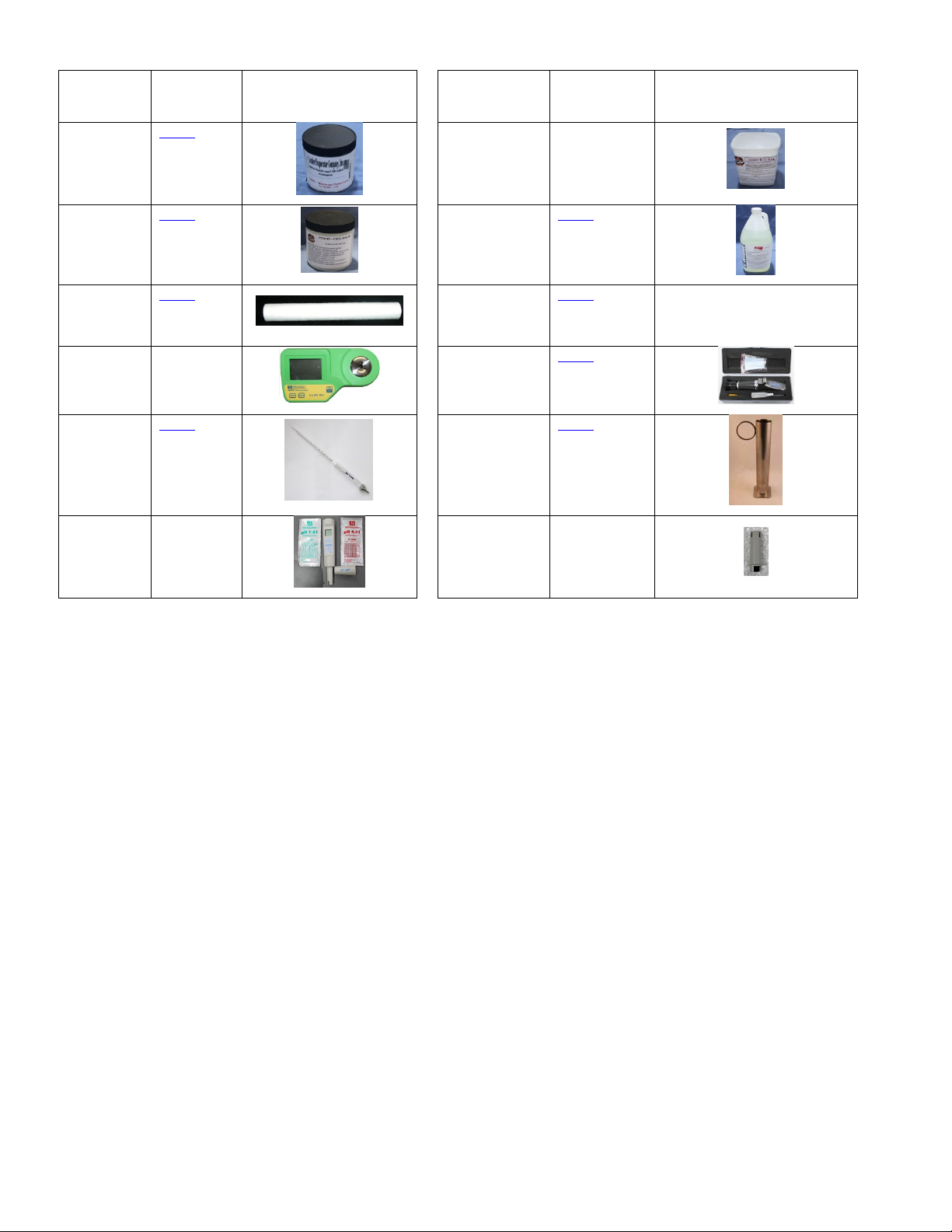
OptionalSetupEquipment,PartsandSupplies
ITEMLEADER
ORDER#DESCRIPTION/PHOTOITEMLEADER
ORDER#DESCRIPTION/PHOTO
Membrane
Preservative,
1lb.
70001
ROSoap5Lbs.69992
CitricAcid,1
lb.
70008
Glycol,1gal.70009
20”
Cartridge
Filter
70012
FoodGrade
Grease
55095
Digital
Refractomet
er
61058
Sap
Refractometer
61073
12”Sap
Hydrometer
61061
Long2”
DiameterTest
Cup
59006
pHMeter61060
pHMeter
Replacement
Probe
61060P
LeaderEvaporatorSpringtechEXTREME6ReverseOsmosisSystemManual Page:12
SETUP
NOTES:
Allmaterialsusedshouldbeapprovedforpotablewater.Nocoppershouldbeused.
Wheninstallingplumbingforthesystem,factorinthesystemmayneedtobemovedforsuchitemsas
maintenance.Itisrecommendedtheconnectionsbemadewithfittingssuchasquickdisconnects.
AllfeedpipingtotheSpringtechLeaderExtremesystemmustbeatleastaslargeasthefeedonthesystem
itself–3”minimumisrecommended
Allinstallationsmustmeetapplicablegovernmentalregulations.
AreaRequired
ThespacetobeusedshouldbecapableofpreventingtheROsystemfromfreezing.Additionallyitwillneedtohave
adequateventilationduringoperationstopreventoverheating.
Thedimensionsofthemainsystemunitare
Width–34”
Length–109”
Height–70”
Aminimumoftwofeetaroundthesystemisrecommended.Youmustalsobeabletoobtainanadditional8feetin
lengthinordertoremovemembranesandpumpassemblies.
Theroomshouldhaveadequatedrainage.Thewalls,ceilingandfloorshouldbeeasytoclean.
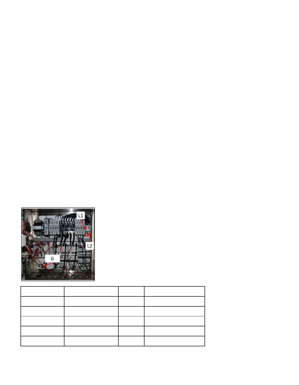
PowerRequirements
Thesystemrequires220V/1Phase,111amps.Allelectricalworkshouldbedonebyalicensedelectricianandmeet
alllocalcodes.
SeeATTACHMENT#1fortheelectricalschematic.
MOTORIDMOTORFUNCTIONSIZE(HP)NAMEPLATEAMPERAGE
M1FeedPump523
M2PressurePump7.530
M3RecirculationPump7.530
M4RecirculationPump314
M5RecirculationPump314
NOTE:Anytimethecontrolpanelisopened,thepowershouldbeturnedoffatthesource.

LeaderEvaporatorSpringtechEXTREME6ReverseOsmosisSystemManual Page:13
GeneralConnectionLayout
ThefollowingillustratesageneralizedlayoutforconnectionswiththeSpringtechEXTREMEROSystem.Thefirst
drawingshowstankconnectionstothesystem.Theseconddrawingshowsanarrangementofvalvestoconnectthe
incomingliquidtothesystem.Dependentonthelocation,otherarrangementsarelikely.Itisbeyondthescopeof
thisdocumenttorecommendthebestlayoutforallsituations.ItisrecommendedyoucontactyourLEADER
EVAPORATORsalespersonoryourlocalDistributor/Dealerforassistanceindecidingthecorrecttanksandlayoutfor
yourneeds.
Simple3TankRODiagram
LiquidSourceSelector
ValvesshouldbeintheR/Oroomforeaseofoperation.Additionalvalvesandtanksmayberequireddependingupon
installation.
NOTE:Wheninstallingthepipingfromthefeedtanksaminimumnumberofelbowsshouldbeused.

LeaderEvaporatorSpringtechEXTREME6ReverseOsmosisSystemManual Page:14
StrainertoValveV6Connection
A3”Y‐strainerissuppliedwiththesystem.Theinputtothestrainerwillneedtobe3”.Plumbingfromthesupply
tanksisrecommendedtobeaminimumof3”ID.Thestrainerisnotmountedtothesystem.Itwillneedtobe
mountedbytheuser.
TheinputtovalveV6is2”.Thesystemissuppliedwitha3”to2”reducingadapter.
Wheninstalling‐maketheconnectionfromthestrainertovalveV6.
Y‐Strainer
Reducingadapter
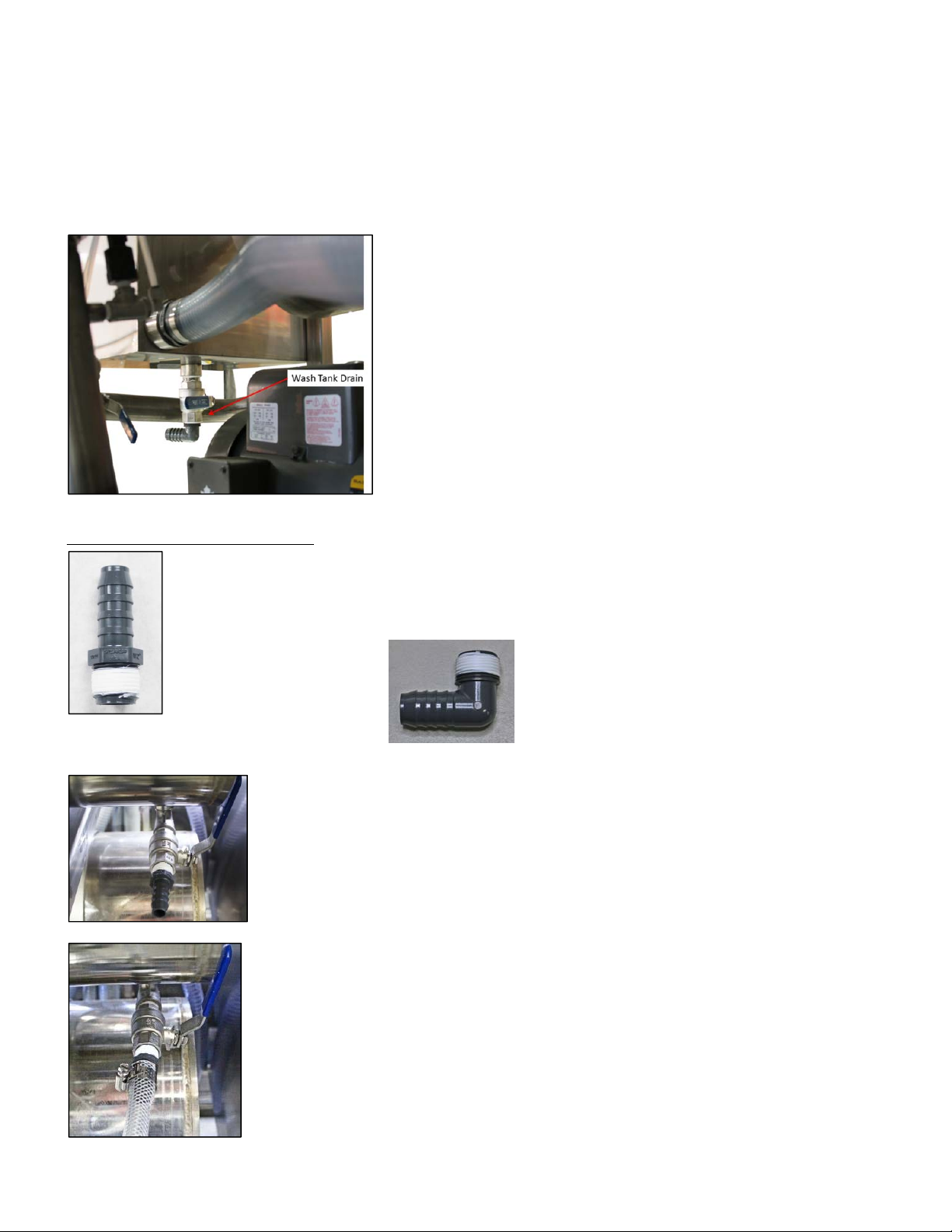
Vessel,Pump,PreFilterCanisterAndWashTankDrains
Thedrainsarelocated:
1undereachpressurevessel
Vesselandpumpdrainsareprovidedwitha½”stainlesssteelballvalve.Vesselsandpumpsbeing
drainedmaycontainconcentrate.Itisrecommendedthesedrainsbesetuptoallowcollectionofthe
liquid.Youwillneed(itemsnotincluded);
8–½”PVCadapters‐optionallytoallowfor90°connectionusecomboelbows
8–½”StainlessSteelbandclamps
8piecesof½”hoselongenoughtoconnecttothedrainadapterandtoreachthecollection
point
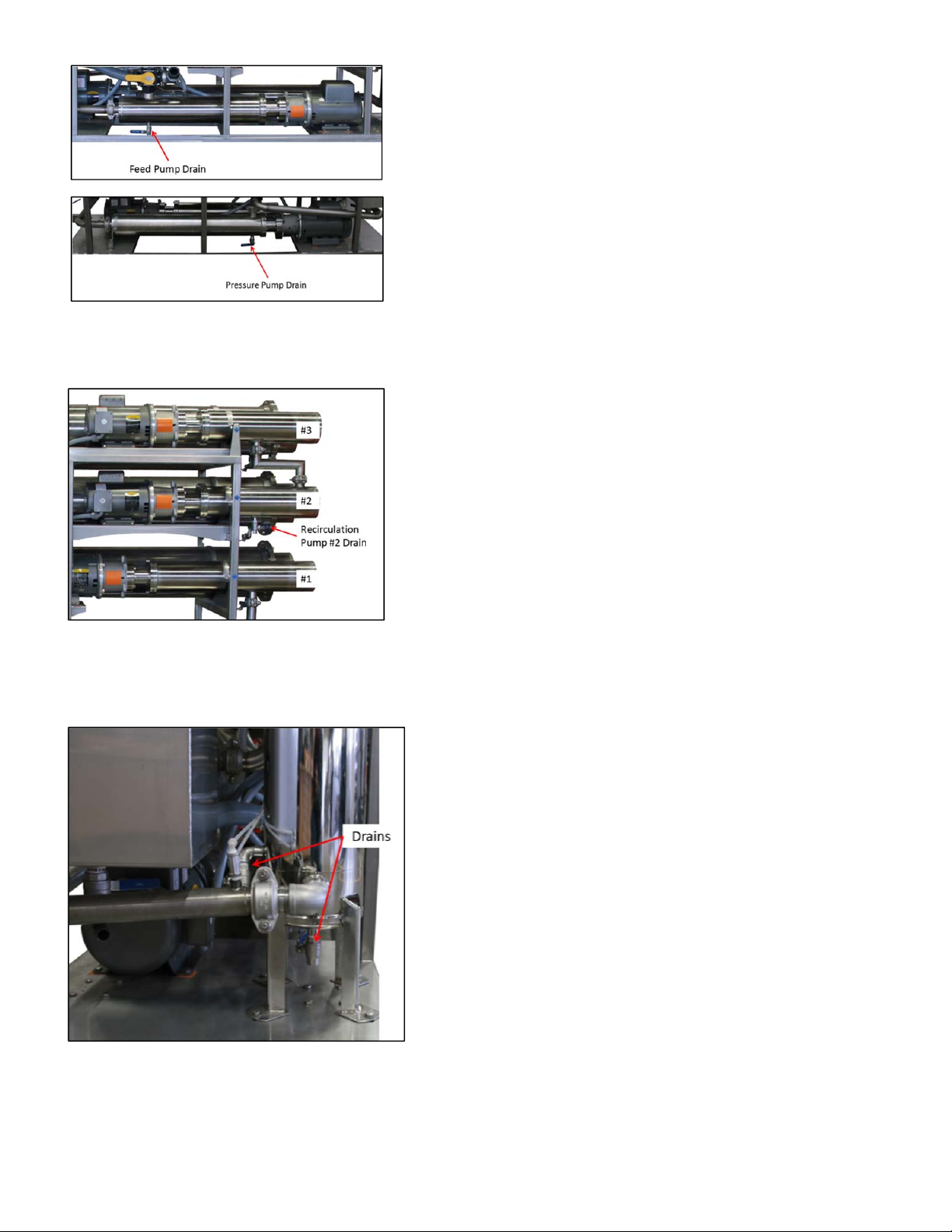
LeaderEvaporatorSpringtechEXTREME6ReverseOsmosisSystemManual Page:15
1underthefeedpump
1underthepressurepump
1underrecirculationpump#2.Recirculationpump#1willdrain
throughthepressurepumpdrain.Recirculationpump#3will
drainthroughrecirculationpump#2drain.
1undertheprefiltercanister
1onthesideoftheprefiltercanister
LeaderEvaporatorSpringtechEXTREME6ReverseOsmosisSystemManual Page:16
Thedrainislocated:
Underthewashtank
Installdrainconnectionsasfollows:
1. TeflontapethePVCadapter.Optionallyifa90°connectionis
preferred,Teflontapeacomboelbowanduseitinplaceofthe
straightadapterswheredesired.
Thewashtankdrainisprovidedwitha1”stainlesssteelballvalve.Tosetupthedrainyouwillneed
(itemsnotincluded);
1–1”StainlessSteelbandclamps
1pieceof1”hoselongtoconnecttothedrainadapterandtoreachthecollectionpoint
2. ThreadthePVCadapterintothestainlesssteelballvalve.
3. Cutthehosetolength(toreachfromtheballvalvetothepointwhereyouwillbe
collectingtheliquid).Placeastainlesssteelbandclampoveroneendofthehose.
SlidethehoseontothePVCadapter.Positionthestainlesssteelbandclampoverthe
hoseontheadapterandtightenthebandclamp.

LeaderEvaporatorSpringtechEXTREME6ReverseOsmosisSystemManual Page:17
V3,V4andV19Connections
V3,V4andV19valvesaretobesetupsotheconnectionscanbeeasilydisconnectedandreconnectedasnecessary.
Thefollowingistherecommendedconnectiondetail.
Inordertoassembletheconnectionsyouwillneed(braidedhoseandclampssoldseparately);
3–CstyleQuickCouplers(two1–½”,one1”)
3(minimum)stainlesssteelbandclamps–(two(minimum)1–½”,one(minimum)1”)
1”IDbraidedfoodgradehosewithlengthtomaketheconnectiontotheConcentratetank.1–½”IDbraided
foodgradehosewithlengthtomaketheconnectiontothePermeatetank.Theconnectiontothedraincanbe
madewithflexiblehose.
V19–ConnectionToDrain
V3–ConnectionToPermeateStorage
1. Cut1–½”IDflexiblehosetoreachfromthevalveV19tothedrain
connection.
2. Placeatleastone1–½”stainlesssteelbandclampoveroneendofthe
hose.
3. Slidethehoseontothe1–½”Cstylequickcoupler.
4. Positionthestainlesssteelbandclamp(s)overthehoseonthecoupler
andtightenthebandclamp(s).
5. Securetheotherendofthehosetothedrainconnection.
6. ConnectthequickcouplersbyopeningthelatchesontheCstylecoupler
(positionthemetallatcharmsoutperpendiculartothebodyofthe
coupler)thenslidingtheCcouplerontotheFcoupler.Pullthemetal
latcharmsbackdowntothesidesoftheCcoupler.
1. Cut1–½”IDfoodgradebraidedhosetolength–fromvalveV3tothe
fillconnectionforthepermeatetank.
2. Placeatleastone1–½”stainlesssteelbandclampoveroneendofthe
hose.
3. Slidethehoseontoa1–½”Cstylequickcoupler.
4. Positionthestainlesssteelbandclamp(s)overthehoseontheadapter
andtightenthebandclamp(s).
5. Securetheotherendofthehosetothepermeatetankfillconnection.
6. ConnectthequickcouplersbyopeningthelatchontheCstylecoupler
(positionthemetallatcharmsoutperpendiculartothebodyofthe
coupler)thenslidingtheCcouplerontotheFcoupler.Pullthemetal
latcharmsbackuptothesidesoftheCcoupler.

LeaderEvaporatorSpringtechEXTREME6ReverseOsmosisSystemManual Page:18
V4–ConnectiontotheConcentrateStorage
1. Cut1”IDfoodgradebraidedhosetolength–fromvalveV4tothefill
connectionfortheconcentratetank.
2. Placeatleastone1”stainlesssteelbandclampoveroneendofthe
hose.
3. Slidethehoseontoa1”Cstylequickcoupler.
4. Positionthestainlesssteelbandclamp(s)overthehoseontheadapter
andtightenthebandclamp(s).
5. Securetheotherendofthehosetotheconcentratetankfillconnection.
6. ConnectthequickcouplersbyopeningthelatchontheCstylecoupler
(positionthemetallatcharmsoutperpendiculartothebodyofthe
coupler)thenslidingtheCcouplerontotheFcoupler.Pullthemetal
latcharmsbackuptothesidesoftheCcoupler.

LeaderEvaporatorSpringtechEXTREME6ReverseOsmosisSystemManual Page:19
OPERATION
WhenstartingtheReverseOsmosisunitthereisasequenceinwhichthepumpswillactivate.PressingtheSTART
buttonwillfirstactivatethefeedpump.Innormaloperationswithin30secondsthefirstpressurepumpwillstart
followedbythesecondpressurepumptheneachofthefeedrecirculationpumps,oneatatime.
Duringanycycleifpermeateisnotavailable,usenonchlorinatedwellorspringwater.
StartupofSystemwithLittleorNoFluid
1. Setthesystemvalvesforarinsecycle(seepage31).
2. Turnoffthepowertothesystematthesource.
3. Openthecontrolboxbyturningthelatchontherightsideofthepanelthenopeningthedoorcarefullytothe
left.
4. Turnoffthepressureandrecirculationpumpbreakers:
NOTE:Breakersarenotshowninthecorrectposition.
BREAKERIDCIRCUITSTARTPOSITION
CB1FeedPumpON
CB2PressurePumpOFF
CB3RecirculationPumpOFF
CB4RecirculationPumpOFF
CB5RecirculationPumpOFF
5. Closethecontrolboxcoverandturnthelatchtofasten.
6. Turnonthepowertothesystematthesource.
7. Ensureyoursourcevalves(waterorpermeate)areopentofeedthesystem.
8. PresstheSTARTbuttontostartthefeedpump.
9. Runthefeedpumpuntilmostofthebubblesaregonefromtheflowmeterslocatedonthefrontofthe
system.Thiswilltake3to4minutes.Notallthebubblescanberemoved.
10. PresstheSTOPbuttontostopthefeedpump.
11. Turnoffthepowertothesystematthesource.
12. OpenthecontrolboxandpositionbreakersCB1,CB2,CB3,CB4andCB5totheONposition.
13. Closethecontrolboxcoverandrefastenthelatches.
14. Turnonthepowertothesystematthesource.
15. Openthepressurepumpfeedbackballvalve.
16. ProceedtotheinstructionsfortheInitialSystemCleaning.

LeaderEvaporatorSpringtechEXTREME6ReverseOsmosisSystemManual Page:20
InitialSystemCleaning
Topreparethesystemaftersetup;
NOTE:IFthesystemhasnotbeenfilledwithfluid,followtheinstructioninthesection“StartupofSystemwithLittleor
NoFluid”.
1. Putapproximately3600USgallonsofnon‐chlorinatedwellorspringwaterintoacleanpermeatestoragetank.
2. Setthevalvesforandrunarinsecycle(seepage31)usingaminimum1800USgallonsofwaterfromthe
permeatetank.Whilethiscycleisrunningcheckallfittings,piping,connectionsandhosesforleaks.Repairas
necessary.
3. AttheendoftherinsecyclechangethepositionofvalveV19sotheliquidflowisdirectedtothewashtank.
Whenthewashtankisapproximately⅔full,returnV19tothedrainposion.
4. MixalkalineR/OsoapwiththeliquidinthewashtankuntiltherequiredpHisreached.Todeterminethe
requiredpH,refertotheMachineSerialNumberDataSheetthatinitiallyaccompaniedthesystem.NOTE:If
themembraneischanged,referencethedatasheetaccompanyingthenewmembrane.
5. Setthevalvesforandrunanalkalinewashcycle(seepage34)allowingthesystemtorununtiltheautomatic
temperatureshutdownat118°F.
6. Setthevalvesforandrunarinsecycle(seepage31)usingaminimum1800USgallonsofwaterfromthe
permeatetank.
7. Runthebenchmarkpermeabilitytest(seepage22).
DataLogging
Dataontheoperationofthesystemshouldberecordedandkept.SeeATTACHMENT#2forthedatasheetformat.
Thefollowingdataisrecorded:
Date–datetheinformationiscollected
Activity–Concentrationcycle(enteraC)orTest(enteraT)
Sap%‐thesugarconcentrationoftherawsap
Concentrate%‐thesugarconcentrationoftheconcentratefromthesystem–testresultsfromthe
concentrateport
Vessel1Flow–gallonsperminuteofpermeatefrommembranes1and2–readingfromthetopofthe
stainlesssteelfloatinthepermeateflowmeter
Vessel2Flow–gallonsperminuteofpermeatefrommembranes3and4–readingfromthetopofthe
stainlesssteelfloatinthepermeateflowmeter
Vessel3Flow–gallonsperminuteofpermeatefrommembranes5and6–readingfromthetopofthe
stainlesssteelfloatinthepermeateflowmeter
ConcentrateFlow–gallonsperminuteofconcentrationfromthesystem–readingfromthetopofthe
stainlesssteelfloatintheconcentrateflowmeter
Temperature–readingfromtemperaturegaugeonthecontrolpanelofthesystem(°F)
FeedPressure–readingfromthepressuregaugeonthecontrolpanelofthesystem(psi)
MembranePressure–readingfromthepressuregaugeonthecontrolpanelofthesystem(psi)
WaterRemoval%‐percentofwaterremovedfromincomingsap–calculatedasfollows
oPERMEATEFLOW–AddallPermeateFlowstogether
oTOTALFLOW‐AddallPermeateFlowsandConcentrateFlowtogether
oDividePERMEATEFLOWbyTOTALFLOWandmultiplytheresultby100
oRecordthisnumberastheWaterRemoval%
GPHProcessed–gallonsperhourbeingprocessedbythesystem‐calculatedasfollows
oTOTALFLOW–AddallPermeateFlowsandConcentrateFlowtogether
oMultiplyTotalFlowby60andrecordtheresultingnumberastheGPHProcessed
Table of contents
Popular Water Filtration System manuals by other brands

Pure Pressure
Pure Pressure Axis Service manual

ubbink
ubbink BioPressure 3000 manual

amiad
amiad AMF-36K Installation and operation instructions

Water Right
Water Right UltroWater Installation, operation & service manual

Anetsberger Brothers
Anetsberger Brothers GoldenFRY FFM-80 Specifications

Filters itm
Filters itm HYDRAULIC-100-V user manual


