Leaksafe Solutions WaterSwitch3 User manual

WaterSwitch3
Installation Instructions

LEAKSAFE SOLUTIONS | WATERSWITCH3 INSTALLATION INSTRUCTIONS
PAGE 2
WATERSWITCH3 COMPONENTS
Valve
Leak Detection
tape available
in 0.3M or 1M
lengths and 1.5M
connecting cable
WaterSwitch3
Valve Control
Wireless Leak
Detection
transmitter
Wireless On/Off Switch
with delay function
Water Flow Meter

1. PROGRAMMING & TEST INSTRUCTIONS
1.1: Programming the WaterSwitch Valve Control
Lift and remove the catch cover on the top of the case. Press the catch underneath to release the front panel.
If the Water Valve Control is to be mains powered or any other auxiliary connections are to be made, cut out cable paths and
connect to terminals as shown in Figure 1.
Install 3 x AA batteries. The Water Valve Control will beep 3 times to indicate correct installation. Plug in to mains supply if a
power adaptor is being used.
Follow the programming Instructions (Sections 1.2 & 1.3) and wireless tests (Sections 1.5.2 & 1.5.4) before mounting the Water
Valve Control in its intended position.
1.2 Water Valve Control – DEFAULT SETTINGS
Set Water Valve Control DEFAULT SETTINGS using the DIP switches and Setting Button on the PCB (Figure 1).
1. To set DO NOT AUTO CHECK THAT A VALVE IS CONNECTED set DIP 1 ON.
DEFAULT = DO AUTO CHECK (DIP 1 OFF). An alarm will sound if valve is disconnected.
2. To set VALVE AUTO CLOSE ON MAINS POWER FAILURE (when using the optional mains power adaptor) set DIP 2 ON. All
other DIPs OFF.
DEFAULT = DO NOT CLOSE VALVE ON MAINS POWER FAILURE (DIP 2 OFF).
Once the DIPs are set, press and hold the Setting Button UNTIL the yellow LED lights and you hear a beep. Release the button
then immediately press and release the button again you will hear another beep and the yellow LED goes out. Return all DIPs to
the OFF position.
LEAKSAFE SOLUTIONS | WATERSWITCH3 INSTALLATION INSTRUCTIONS
PAGE 3
Wired aux ON/OFF
via BM system to
open/close valve(s)
OV = common Volt free output relay
Setting DIPs switches
Input L for directly
connected leak
detection tape
Setting button
Yellow LED
2nd valve
connection (optional)
green = open
black = OV
red = close
Input V for 5VDC Valve
Input F for Flow
Meter (optional)
3 x AA 1.5 batteries
Mains Power Adaptor
connection 9VDC-
‐12VDC 300mA
Figure 1. Water valve control, switches and connections

PAGE 4
LEAKSAFE SOLUTIONS | WATERSWITCH3 INSTALLATION INSTRUCTIONS
1.3 Water Valve Control – FLOW OR NO FLOW VALVE AUTO CLOSE (Requires installation of a Flow Meter).
Set using the DIP switches and Setting Button (Figure 1) and with reference to the tables below.
1.4 Initialising the Water Valve Control and testing the Valve Open & Close functions
WARNING: Do not inser t ngers or any other object into the valve whilst it is operating.
1. Ensure a Valve is connected to input ‘V’ on the bottom of the Water Valve Control.
2. Press the ‘WATER ON’ button it beep once. The green ‘VALVE OPERATING LED’ will ash for 10 seconds.
3. When the ‘VALVE OPERATING LED’ stops ashing, press the ‘WATER OFF’ button it will beep twice. The green
‘VALVE OPERATING LED’ will ash for 10 seconds, and the valve will close.
4. Press the ‘WATER ON’ button to re-open the valve.
Once the DIPs are set, press the Setting Button and then IMMEDIATELY release. The Water Valve Control will beep once to conrm
that the settings are stored in memory.
Reassemble Water Valve Control.
Time DIP 1 DIP 2 DIP 3
30 minutes (Factory default) 000
1 hour 100
1.5 hours 010
2 hours 110
4 hours 001
6 hours 101
OFF 011
Engineer use* 111
0 = OFF / 1 = ON
SET THE ALLOWED CONTINUOUS FLOW TIME LIMIT
Set DIPs 1, 2 & 3 to set the amount of time water may ow
continuously before the Valve closes
*Valve size 20mm – 42mm: 5 minute engineer test. Valves 54mm +: 20 minute engineer test
Time DIP 4 DIP 5 DIP 6
6 hours 000
12 hours 100
18 hours 010
24 hours 110
36 hours 001
48 hours 101
OFF (Factory default) 011
Engineer use* 111
0 = OFF / 1 = ON
SET THE ALLOWED NO FLOW TIME LIMIT
Set DIPs 4, 5 & 6 to set the time delay before the Valve closes
when no water ow is detected
If set time is exceeded the Valve will close but the Water Valve
Control will NOT alarm.
If set time is exceeded the valve will close and the Water Valve
Control will alarm.

PAGE 5
LEAKSAFE SOLUTIONS | WATERSWITCH3 INSTALLATION INSTRUCTIONS
1.5.1 Enrolling a Wireless Leak Detection Transmitter
1. Remove the cover from the wireless transmitter. Leave the batteries out.
2. Press ‘ENROL’ on the Water Valve Control until yellow ‘WARNING LED’
lights, then press ‘ENROL’ again until green ‘VALVE OPERATING LED’
starts to ash.
3. Hold down the brown ‘TEST’ button in the wireless transmitter (Figure
2) and install 2 x AA batteries. Release the ‘TEST’ button and the red
LED in the transmitter will ash and beep. You have 5 minutes to enrol
the transmitter.
4. Make sure there is at least a 2M distance between the Valve Control and
the Wireless Transmitter.
5. Press the ‘TEST’ button in the transmitter again, it will beep, and the
Water Valve Control will also start to beep.
6. Press the ‘ON’ button on the Water Valve Control to enrol the two
components. The transmitter will beep three times to conrm the
enrolment.
Repeat the procedure for any other wireless transmitters and when all
transmitters are enrolled press ‘OFF’ on the Water Valve Control to exit
enrol mode.
1. 5 Enrolling and testing a Wireless Leak Detection Transmitter or Wireless On/Off switch
1. Assemble a length of leak detection tape (see Section 2.5). Plug
the Leak Detector tape and connecting cable into the Wireless
Leak Detector Transmitter. (Figure 3).
2. Check the valve is open.
3. Ensure the transmitter is at least 2 metres away from the Water
Valve Control.
4. Wet the test pins at the end of the Leak Detection tape. The
red LED ‘Leak Alarm’ on the Water Valve Control will ash,
the Water Valve Control will beep and the valve will close. The
wireless transmitter will also emit an audible alarm and the
internal red LED will ash all the time the test pins are wet.
5. Remove one battery from the Wireless Transmitter to stop the
audible alarm, then reposition the battery in the transmitter and
replace the transmitter cover.
6. Reset the Water Valve Control: Press the ‘WATER OFF’ button
on the Water Valve Control and it will beep once. The audible
alarm and red LED ashing will stop but the Valve will remain
closed. Press the ‘WATER ON’ button - it will beep once, and the
Valve will open.
Figure 2.
Test Button
Figure 3.
1.5.2 Testing the Wireless Leak Detector Transmitter and Leak Detector Tape
NB. If you inadvertently wet the tape rather than its test pins, you will have to disconnect the tape from the wireless
transmitter before you will be able to reset the system. Ensure the tape is dry before reconnecting or the system will
immediately alarm and close the valve again. The tape can be dried naturally or by using a hairdryer on a medium setting.

PAGE 6
LEAKSAFE SOLUTIONS | WATERSWITCH3 INSTALLATION INSTRUCTIONS
1.5.4 Testing the Wireless On/Off Switch
1. Ensure the wireless On/Off switch is at least 2 metres away from the Water Valve Control. Press the ‘OFF’ switch. The blue LED
indicator on the switch will ash, the Water Valve Control will beep twice to conrm a wireless signal has been received, and
the wireless switch will ash red and beep twice to conrm that the command has been acknowledged. The valve will close.
2. Press the ‘ON’ switch. The blue LED indicator on the switch will ash, the Water Valve Control will beep once to conrm a
wireless signal has been received, and the wireless switch will ash green and beep once to conrm that the command has
been acknowledged. The valve will open.
1.6 Deleting the Water Valve Control memory
This will clear ALL enrolled wireless devices – wireless leak detector transmitters and wireless On/Off switches and reset the
Default Settings and Continuous Flow or No Flow settings to factory default (see Sections 1.2 & 1.3).
1. Press and hold down the ‘OFF’ button until the red ‘LEAK ALARM LED’ lights, release and press ‘OFF’ button again. The Water
Valve Control will beep 3 times to conrm that it has returned to factory default settings.
1.5.3 Installing batteries and enrolling a Wireless On/Off Switch
1. Slide backplate of wireless switch down to release the catches. Insert a
small at bladed screwdriver into the openings on the left of the switch
and turn gently, the cover will separate from the backplate.
2. Install the 2 x CR2032 batteries in the wireless switch.
3. Press and hold ‘ENROL’ on the Water Valve Control until yellow
‘WARNING LED’ lights, release then press ‘ENROL’ and release again,
and the green ‘VALVE OPERATING LED’ will start to ash.
4. Make sure there is at least a 2M distance between the Valve Control and
the Wireless Switch.
5. Press and hold the 1h button on the wireless switch until the green light on
the switch ashes, release and press 1h again then press ‘ON’ to send the
enrol signal. The Water Valve Control will start to beep. Press ‘ON’ on the
valve control to accept the enrol command.
6. Press ‘OFF’ on the wireless switch to exit enrol mode on the switch and
press ‘OFF’ on the Water Valve Control to stop enrol mode on the Control.
Wireless On/Off Switch
with delay function

PAGE 7
LEAKSAFE SOLUTIONS | WATERSWITCH3 INSTALLATION INSTRUCTIONS
2. INSTALLATION INSTRUCTIONS
2.1 Installing the Motorised Valve and Water Valve Control
Install the Motorised Valve as close to the incoming stopcock on the incoming water main as possible, on the property owner’s side.
Leaksafe recommend the use of compression joints when installing the Motorised Valve although soldered, speed t or similar
couplings can be used.
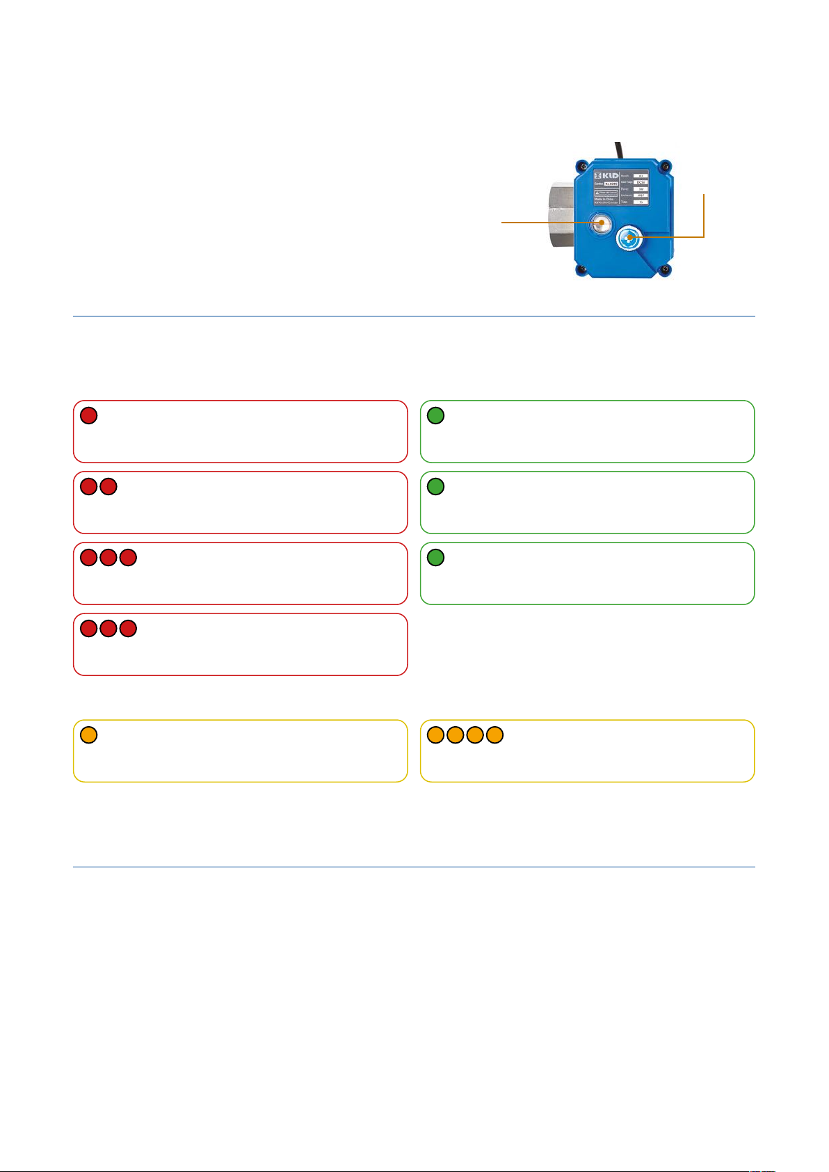
Install the valve with the blue actuator positioned for easy access to the manual operating button and a clear view of the window
that shows if the valve is open or closed (Figure 8). DO NOT hold or use the blue actuator when tightening any connections as this
will damage the valve assembly.
Locate the Water Valve Control at the highest practicable point off the oor to maintain a strong wireless signal.
Using the back plate of the Water Valve Control as a template, x two screws (not supplied) on which to hang the unit. Do not over
tighten the screws, it is important to be able to remove the Water Valve Control by lifting it off the screws.
Connect the valve to the input marked ‘V’ on the bottom of the Water Valve Control.
2.3 Installing the Wireless On/Off Switch
The Wireless On/Off Switch must be installed at least 2 metres away from the Water Valve Control and will work up to 25 metres
away. The distance over which the wireless signal will work will depend on a number of factors including building construction,
position of the Water Valve Control and Wireless On/Off Switch and in some instances the effect of interference from other
wireless or electronic devices.
Test the wireless signal between the Wireless On/Off Switch and the Water Valve Control before installation by temporarily
positioning them in the location where they are intended and repeating the wireless signal test given in Section 1.5.4. All
components should be positioned as high as practicable off the ground to maximise the wireless signal.
The Wireless On/Off Switch can be screwed to a surface, or xed to the wall using the double-sided adhesive xing pads supplied.
2.2 Installing the Flow Meter (if installed)
The Flow Meter can be installed either before or after the valve depending on
the available amount of room on the pipe, however it must be positioned before
any tee off points and its’ connecting cable must be able to reach the Water
Valve Control. It can be installed horizontally or vertically but must be aligned so
that the ow in the pipe is in the same direction as the arrow on the meter body.
Connect the Flow Meter to the input marked ‘F’ on the bottom of the Water
Valve Control.
Figure 5.
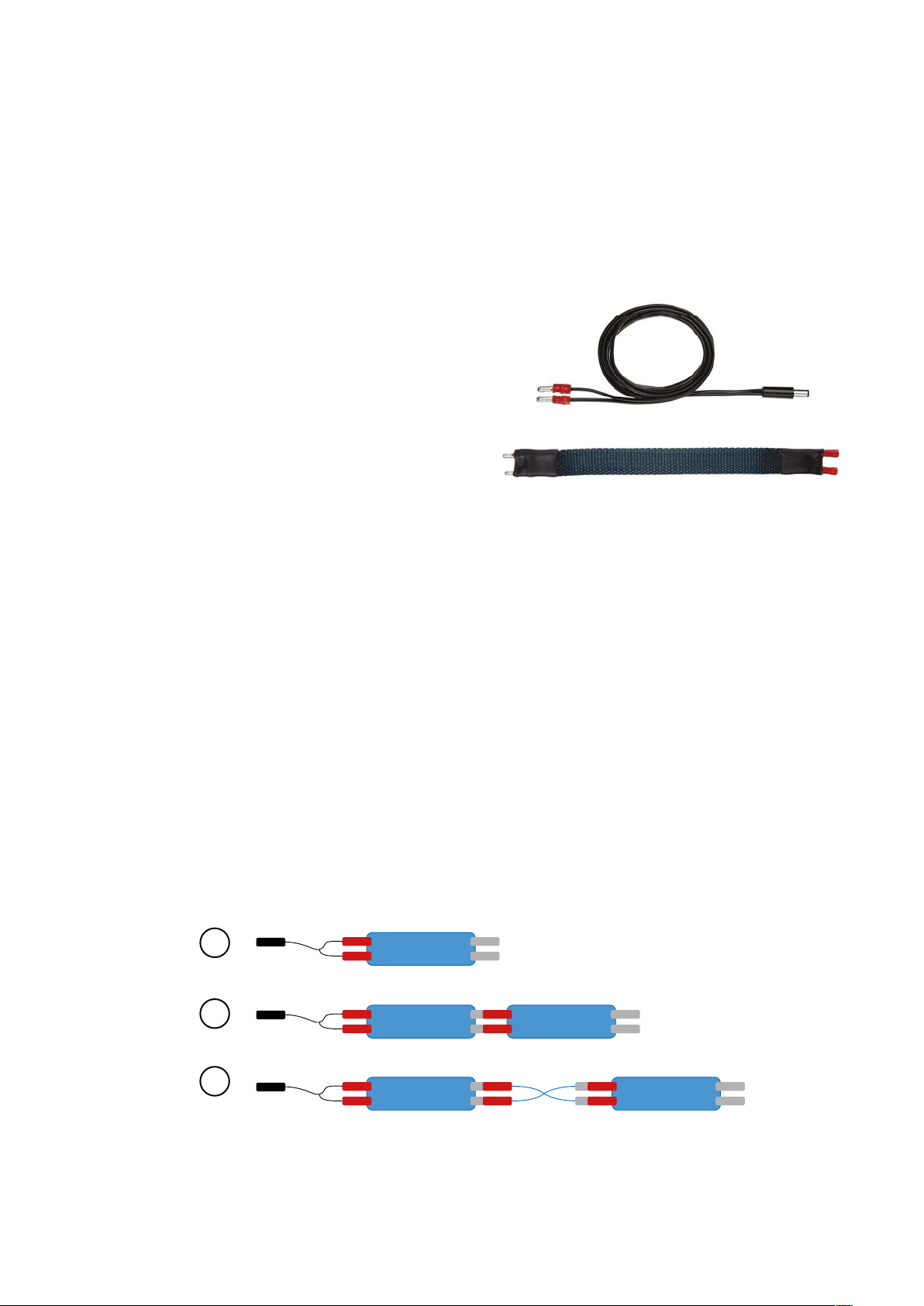
2.4 Installing a Wireless Leak Detector Transmitter and Leak Detection tape
A Wireless Leak Detector Transmitter and Leak Detection tape can be installed up to 25 metres away from the Water Valve Control.
The distance over which the wireless signal will work will depend on a number of factors including building construction, position of the
Water Valve Control and Wireless Transmitter and in some instances the effect of interference from other wireless or electronic devices.
Test the wireless signal between the Wireless Leak Detector Transmitter and the Water Valve Control by temporarily positioning
all the components in the location where they are intended and testing in those locations before installation (Section 1.5.2).
Position the transmitter as high as possible off the ground to maximise the wireless signal.
Installation
Fix using self-adhesive xing pads or Velcro. Ensure that the transmitter’s connection cable hangs vertically and the Leak
Detection tape can be positioned where needed.

PAGE 8
LEAKSAFE SOLUTIONS | WATERSWITCH3 INSTALLATION INSTRUCTIONS
Tools required:
Crimping plier suitable for securing red pre-insulated terminals
(bullet connectors).
NB. If lengths of leak detection tape are being daisy chained
together with interconnection cable between each length of tape,
you will also require:
• Red 0.5 - 1.5 mm² Insulated Male and Female Crimp Bullet
Connectors/Terminals with a copper sleeve and ared vinyl
insulation.
• 2 core audio cable.
Assembly (see Figure 7)
1. To connect the 1.5M connection cable to a single length of leak
detection tape crimp the female bullet connectors at the end of
the connection cable into the male bullet connectors on the leak
detection tape.
Plug the connecting cable in to Input ‘L’ on the Water Valve
Control or the cable on the bottom of the Wireless Leak
Detection Transmitter.
Figure 6.
Leak detection tape components
1
2
3
Figure 7.
3. To connect the 1.5M connection cable to two or more lengths of leak detection tape with interconnecting 2 core cable between,
crimp the female bullet connectors at the end of the 1.5M cable into the male bullet connectors on the rst length of leak
detection tape. Cut the required length of 2 core cable and strip the insulating sheath off either end of the cable to expose the
wire. Crimp 2 male bullet connectors to the wires at one end and 2 female bullet connectors at the other, then crimp the test
pins on the rst tape in to the female bullet connectors on the connecting cable and the male bullet connectors on the cable
into the female connectors on the next length of tape. A maximum of 30M of tape and interconnecting cable can be connected
in this way.
Connect to the wireless Leak Detection Transmitter or Water Valve Control as detailed above.
2.5 Assembling Leak Detection tape and connecting cables:
2. To connect the 1.5M connection cable to two lengths of leak detection tape to make a longer length of tape, crimp the female
bullet connectors at the end of the cable into the male bullet connectors on the rst length of leak detection tape, then crimp
the test pins of that tape in to the female bullet connectors on the next length of tape. A maximum length of 30M of tape can
be connected in this way.
Connect to the wireless Leak Detection Transmitter or Water Valve Control as detailed above.

PAGE 9
LEAKSAFE SOLUTIONS | WATERSWITCH3 INSTALLATION INSTRUCTIONS
3. RESETTING AND OPENING THE VALVE AFTER A LEAK ALARM
The Water Valve Control will shut the valve on the incoming water main or pipe if a leak detection tape is in contact with water, or
if the No Flow or Continuous Flow set times are exceeded.
3.1 Resetting the system after a leak has been repaired or Continuous Flow limits are exceeded
1. Press the ‘WATER OFF’ button on the Water Valve Control to mute the alarm – the valve remains closed. If the alarm continues,
and you have a detection tape directly connected to the Water Valve Control, disconnect the tape then press the ‘WATER OFF’
button on the Water Valve Control to mute the alarm.
2. Identify where in the property the leak has occurred.
3. If you have wireless leak detector transmitters installed the one that has instigated the alarm will be beeping. If none of the
Transmitters are beeping but you have a leak detection tape or tab directly connected to the Water Valve Control then this is
where the leak is.
4. Repair the leak and dry the leak detection tape. Tapes should be unplugged and dried either naturally, or with a hairdryer on a
medium setting held 1M away from the tape, or on a warm (not hot) radiator.
5. Reposition and reconnect the tape once dry.
6. Press ‘WATER ON’ on the Water Valve Control to open the valve.
3.2 Resetting the system after a No Flow limit is exceeded
If the valve has closed because the No Flow limit is exceeded press the ‘WATER ON’ button on the Water Valve Control or wireless
On/Off switch to open the valve and reinstate the water.
3.3 Isolating a leak and turning the water on
Leaksafe recommend you repair all leaks before the mains water is turned back on.
Where a detected leak is from an appliance e.g., a washing machine, and the leak can be contained by not using that appliance, it
is possible to isolate that zone to allow the Leaksafe system to be reset and the water turned back on.
IF LEAK DETECTION IS DISABLED IN ANY PART OF A PROPERTY THAT ZONE IS UNPROTECTED. THE DECISION TO DISABLE
ANY PART OF A LEAKSAFE SYSTEM LIES WITH THE OCCUPIER AND LEAKSAFE ACCEPTS NO LIABILITY WHATSOEVER FOR
THE CONSEQUENCES OF THAT DECISION.
To isolate a zone:
1. Unplug the leak detection tape protecting that zone from the Wireless Transmitter or Water Valve Control.
2. Press ‘WATER OFF’ on the Water Valve Control.
3. Press ‘WATER ON’ on the Water Valve Control to open the valve and restore water to the property.
IMPORTANT: When the leak is repaired, REMEMBER TO DRY AND RECONNECT THE LEAK DETECTION TAPES.

PAGE 10
3 red ashes & no beeps every 15 seconds
VALVE CLOSED DUE TO NO FLOW TIMER BEING
EXCEEDED
Rapid beeping for 15 seconds then 3 red ashes &
3 beeps every 60 seconds
VALVE CLOSED DUE TO WATER CONTINUOUS
FLOW TIMER BEING EXCEEDED
Rapid beeping for 15 seconds then 2 red ashes &
2 beeps every 60 seconds
VALVE CLOSED DUE TO A WATER LEAK
BEING DETECTED
Rapid beeping for 15 seconds then 1 red ash & 1
beep every 60 seconds
VALVE CLOSED DUE TO MAINS POWER FAIL
(if this option was selected)
Green ashing every second & 2 beeps
VALVE CLOSING
Fast green ashing every 0.5 second & 1 beep
VALVE OPENING
Solid green
WATER VALVE CONTROL OPERATING ON MAINS
POWER
4 orange ashes & 4 beeps every 60 seconds
VALVE HAS BECOME DISCONNECTED FROM
WATER VALVE CONTROL (if this option was
selected)
1 orange ash & beep every 60 seconds
LOW BATTERIES, CHANGE BATTERIES ASAP
4. INDICATORS AND ALARMS
LEAK ALARM VALVE OPERATING
WARNING
LEAKSAFE SOLUTIONS | WATERSWITCH3 INSTALLATION INSTRUCTIONS
3.4 Manual override on the Motorised Valve
To manually operate the valve, lift and turn the operating
button (Figure 8). When the valve is open the red line in the
valve status window is parallel to the water pipe and at
right angles when closed.
Push operating button down when nished.
Manual
operating
button
Valve
status
window
Support and FAQ’s are available to view or download at www.leaksafe.com/support
Figure 8.

PAGE 11
LEAKSAFE SOLUTIONS | WATERSWITCH3 INSTALLATION INSTRUCTIONS
QUICK USER GUIDE
1. Turning water ON or OFF using the WaterSwitch Valve Control
To turn the water ‘ON’, press the ‘WATER ON’ button on the WaterSwitch Valve Control you will hear a beep and the valve
will open.
To turn the water ‘OFF’, press the ‘WATER OFF’ button you will hear 2 beeps, and the valve will close.
2. Turning water ON or OFF using a wireless On/Off switch
To turn the water ON
Press the ‘ON’ switch. The blue LED indicator on the switch will ash, the Water Valve Control will beep once to conrm a
wireless signal has been received, and the wireless switch will ash green and beep once to conrm that the command has
been acknowledged. The valve will open.
Turning the water OFF
Press the ‘OFF’ switch. The blue LED indicator on the switch will ash, the Water Valve Control will beep twice to conrm a
wireless signal has been received, and the wireless switch will ash red and beep twice to conrm that the command has
been acknowledged. The valve will close.
3. Resetting the system after a leak alarm or Continuous Flow limits are exceeded
The Water Valve Control will shut the valve on the incoming water main or pipe if a leak detection tape is in contact with
water, or Continuous Flow set times are exceeded.
Press the ‘WATER OFF’ button on the Water Valve Control to mute the alarm – the valve remains closed. If the alarm
continues, and you have a detection tape directly connected to the Water Valve Control, disconnect the tape then press the
‘WATER OFF’ button to mute the alarm.
Identify where in the property the leak has occurred.
If you have wireless leak detector transmitters installed the one that has instigated the alarm will be beeping. If none of the
Transmitters are beeping but you have a leak detection tape or tab directly connected to the Water Valve Control then this
is where the leak is.
Repair the leak and dry the leak detection tape. Tapes should be unplugged and dried either naturally, or with a hairdryer
on a medium setting held 1M away from the tape, or on a warm (not hot) radiator.
Reposition and reconnect the tape once dry.
Press ‘WATER ON’ on the Water Valve Control to open the valve.
4. Resetting the system after a No Flow limit is exceeded
If the valve has closed because the No Flow limit is exceeded press the ‘WATER ON’ button on the Water Valve Control or
wireless On/Off switch to open the valve and reinstate the water.
5. Isolating a leak and turning the water on
Leaksafe recommend you repair all leaks before the mains water is turned back on. See important notes in Section 3.3
Where a detected leak is from an appliance e.g., a washing machine, and the leak can be contained by not using that
appliance, it is possible to isolate that zone to allow the Leaksafe system to be reset and the water turned back on.
To isolate a zone:
1. Unplug the leak detection tape protecting that zone from the Wireless Transmitter or Water Valve Control.
2. Press ‘WATER OFF’ on the Water Valve Control.
3. Press ‘WATER ON’ on the Water Valve Control to open the valve and restore water to the property.
IMPORTANT:
When the leak is repaired, REMEMBER TO DRY AND RECONNECT THE LEAK DETECTION TABS OR TAPES IN THAT AREA.

Version 1 - December 2021
Leaksafe Solutions Limited
Unit C Rose Court, 89 Ashford Road, Bearsted, Maidstone, ME14 4BS, United Kingdom
Tel: 0344 848 0488 Web: www.leaksafe.com Email: [email protected]
Other manuals for WaterSwitch3
1
Table of contents
Other Leaksafe Solutions Water System manuals
Popular Water System manuals by other brands

Perma-Trade
Perma-Trade PT-P25 instruction manual

A.O. Smith
A.O. Smith LILY user manual

Pattfield
Pattfield PE-HWA 630 Translation of the original instructions

Rinnai
Rinnai PRESTIGE Operation & installation manual

Amtrol
Amtrol 2-AS Installation & operation instructions

Pool Controls
Pool Controls Chemigem D10CP user manual