LeakSmart Hub 3.0 User manual

Hub 3.0 Installation
Instructions
User Interface
A. Wi-Fi Button – To Reset the Wi-Fi credentials of the LeakSmart Hub 3.0.
B. Power ON/OFF – A Switch to turn ON/ turn OFF the LeakSmart Hub 3.0.
Note: Battery is only backup supply. User must use power adapter in order to switch ON the device.
C. Factory Reset – Factory reset the LeakSmart Hub 3.0.
Note: All the paired sensor devices will be removed after factory reset.
D. User Indication LED – Single RGB color LED is used to provide user indications to show system status.
LED User indications are dened as per below table:
•
Primary Supply – 5V DC adapter supply.
•
Secondary Supply – Battery supply.
Setting up your LeakSmart System is as simple as launching
the LeakSmart App and pairing your devices.
User LED
Indication Wi-Fi Button
Power On/O
Factory Reset
5v Power
Adapter Jack
page 1
Item# 8850830
Battery Compartment
(18350 Lion)
+
_

Red No Wi-Fi Connection No Wi-Fi Connection
Red Blinking No Internet Access No Internet Access
Blue System is OK NA
Green Blinking Initializing Pairing Mode Initializing Pairing Mode
Green Firmware upgrade in progress Firmware upgrade in progress
Yellow-Orange NA System is OK, running on battery
Yellow-Orange Blinking NA LOW Battery
Light Purple Factory Reset in progress Factory Reset in progress
Red and Blue blinking Abnormal Condition Abnormal Condition
Hub Operation
LED Indication Primary Supply Secondary Supply
Hub Installation Instructions
page 2
CAUTION: Read installation instructions BEFORE installing your
LeakSmart
Hub. The setup instructions
below show IOS application screen examples. The setup process is the same on an Android device, but the
app screens will appear dierent on an Android device.
1. Centrally locate the Hub in your home to get the best coverage. Ideal spot is
on the main level of your home.
2. Connect the power supply to the hub. Note: make sure the cord used, is identied
with a ag stating “Hub Only”.
3. Switch on the On/O switch. Once powered, a solid Red LED light will indicate
on the top of the hub.
Setup and Operation
User LED
Indication
Power
On/O
5v Power
Adapter Jack

Hub Installation Instructions
4. Download the LeakSmart app to your
smart device from the Apple App
Store or Google Play.
5. Create an account and password.
Once created, an activation link will
be sent to your account email
address.
Click the link in your email to launch
the LeakSmart app, then sign in.
6. On the home page of the LeakSmart
app, tap on add hub.
The app will then walk you through
the set up procedure.
Setup and Operation
page 3

Hub Installation Instructions
page 4
7. Before connecting the Hub to Wi-Fi make sure
the LED satus light on the top is solid red.
If the LED light does not appear solid red, reset
the Wi-Fi congurations by holding the hub’s
Wi-Fi button for 5 seconds.
8. Switch over to phone settings, network
Wi-Fi settings.
Keep the LeakSmart app open in the
background during this process.
Setup and Operation

Hub Installation Instructions
page 5
8. In your Wi-Fi settings, the LeakSmart Hub will appear
within the list of available Wi-Fi networks as
leakSMART– XXXX
Note: the 4 digit XXXX code is the last four digits of the
MAC address tied to your LeakSmart Hub.
Select leakSMART – XXXX network name to connect
the hub.
Note: if the leakSMART – XXXX network is not
displayed as one of the Wi-Fi networks, you’ll have to
reset your Hub by hitting the pinhole reset button
located on the back of the hub.
9. After successful connection with the leakSMART –
XXXX network, switch back to the LeakSmart app.
Setup and Operation

Hub Installation Instructions
page 6
10. Once you’re back into the LeakSmart App, select your
home Wi-Fi network that you would like to connect
your LeakSmart Hub to.
The screen will display all the available Wi-Fi
networks detected by the Hub 3.0.
11. Enter password for your selected Wi-Fi network.
Tap on “connect” button when complete
Setup and Operation

Hub Installation Instructions
page 7
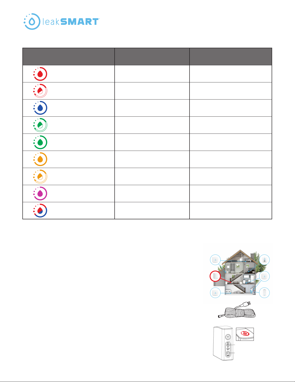
12. When the hubs LED indicator light turns blue, the hub
has been successfully activated to your account.
13. You are now ready to pair all other devices to your
LeakSmart System. Simply tap on add devices and
follow the in app instruction screens.
Visit www.leaksmart.com/installation to download
the valve or sensor instruction sheet for next steps on
how to pair a specic device.
Setup and Operation
Transfer of ownership.
• In order to reactivate the hub on someone else’s account, that hub must rst be deleted from the
original owner’s app, then locally reset the hub in following the below procedure.
• Reset your hub by hitting the pinhole reset button located on the back of the hub. The LED
indicator light will turn purple. then switch o then back on using the power switch. The LED will
then change to solid red
Note 1: Sometimes the device may require that it be power cycled in advance of
the 15 second hold. This is done by switching o then back on using the
power switch.
Note 2: If resetting the hub with the pin hole reset, all the devices will be removed from the system
and the hub will require reactivation.
LeakSmart
Bedford Heights, Ohio 44146
Designed in U.S.A. Made in China.
©2018 LeakSmart® Inc.
Customer Service: 1-855-532-5768
Technical Support: 1-855-532-5457
To learn more visit, leaksmart.com
To register your product visit: LeakSmart.com/product-registration
LeakSmart® Snap FCC Compliance
FCC: W72-ZICM357SP1, IC:8254A-ZICM357SP2
This equipment has been tested and found to comply with the limits for a Class B digital device,
pursuant to part 15 of the FCC Rules. These limits are designed to provide reasonable protection against
harmful interference in a residential installation. This equipment generates, uses and can radiate radio
frequency energy, and if not installed and used in accordance with the instructions, may cause harmful
interference to radio communications. However, there is no guarantee that interference will not occur in
a particular installation. If this equipment does cause harmful interference to radio or television
reception, which can be determined by turning the equipment o and on, the user is encouraged to try
to correct the interference by one or more of the following measures:
• Reorient or relocate the receiving antenna
• Increase the separation between the equipment and the receiver
• Connect the equipment into an outlet on a circuit dierent from that to which the receiver is connected
• Consult the dealer or an experienced radio/TV technician for help
Table of contents
Popular Switch manuals by other brands

HPE
HPE Aruba 6200F Installation, Safety, and Regulatory Information

Panduit
Panduit Atlona AT-OME-RX31 manual

Grandbeing
Grandbeing GB07_SW0402X operating instructions

Moxa Technologies
Moxa Technologies ToughNet TN-5516 Series Hardware installation guide

Northern Telecom
Northern Telecom DMS-100 Series user guide

Omron
Omron A22S - datasheet