0
1
2
3
4
PARTS LIST (4s)
Machine bolts
1 - 7/16 X 3½" (12 mm 90 mm)
1 - ¼" x 3" (lams)
Round head screw
2 - #12 x 1½" (shelf)
6 - #14 X 2" (breast beam,
lower cross member
8 - # 12 x 1½" (jack box)
2 eye screws
Tacks for canvas
1 book Warp&Weave
1 VHS Video cassette
mounting instructions
PAGE 5
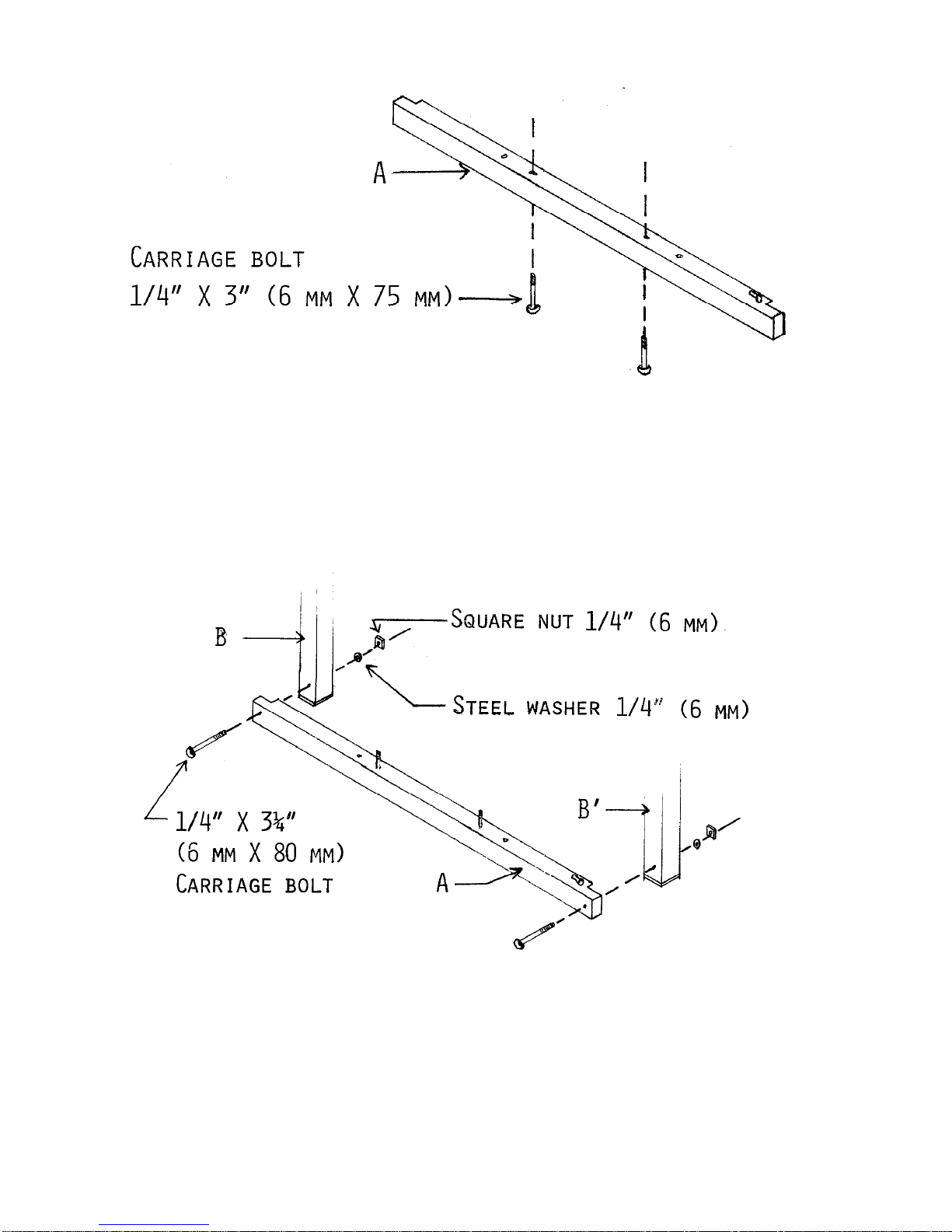
Carriage Bolts
2 - ¼ X 3¼" (6 mm x 80 mm)
2 - ¼" X 3" (6 mm x 75 mm)
2 - ¼" X 1¾" (6 mm x 45 mm)
4 - 5/16 X 2½" (8 mm x 65 mm)
Nuts
3 - ¼" (6 mm) (lam, treadle cross-member)
2 - 5/16" (8 mm)(batten handtree)
Wing nuts
4 - ¼" (6 mm) (treadle block(2), frame hooks)
2 - 5/16" (8 mm)(batten handtree)
Washers
4 - 5/16" (8 mm)(batten)
5 - ¼" ( 6 mm)
2 - 9/16' (15 mm)(treadle block)
Wooden spacer
5X
1½"