5
HMM-16FX
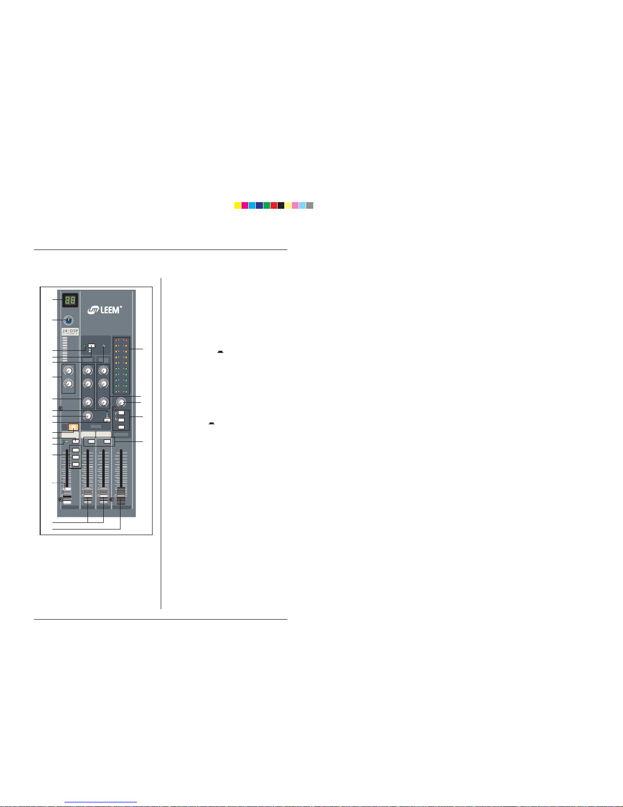
Front Panels Controls
Front Panels
This indicator lights when the PFL switch is turned on.
(11). PFL SWITCH
When these switch is depressed, the channel input
signal can be routed to the PFL bus.
This switch allows you to monitor the pre-fader chan-
nel input signal through headphone outputs and
control room outputs.
(12).ASSIGN SWITCHES
Use these switches to send the channel’s signal to the
Group1-2 , Group 3-4 and/or MAIN L/R buses. Setting
the switch on ( ) causes the signal to be sent to the
corresponding group buses.
(13). CHANNEL FADER
This is the channel’s main level control. It determines
the level of the signal that is sent from the channel to
the master mixing, group outs and effect buses. It is
the settings of the input channel faders that determine
the mix, or the balance of sound levels between the
instruments or other sources connected to the inputs.
When a channel is not being used, its fader should be
set at the minimum position to prevent the addition of
unwanted noise to the main program signal.
(5). AUX 1 AND AUX 2 CONTROLS
This AUX1 knob controls the signal level that the chan-
nel sends to the AUX1 bus; the AUX2 knob controls
the signal level to the AUX2 bus.
If you are using stereo channels , the signals from the
L and R channels are mixed and send to the AUX1 and
AUX2 buses.
These controls are placed before the channel fader ,so
they control the AUX outputs regardless of the setting
of the channel fader.
(6). PRE/POST SWITCH
This button determines whether the AUX2 signal is Pre
or Post fader. Pre means not affected by the position
of the channel fader. Post means is affected by the
position of the channel fader.
Note that switch applies to AUX2 only. The signal to
the AUX1 bus always passes through the channel
fader first
(7). EFX CONTROL.
This knobs control the level of the signals sent to EFX
bus. The channel signals mixed by this bus have their
overall level set by the EFX SEND Control to the EFX
SEND jack on the front panel. The EFFECT bus signal
is also fed into the internal digital signal processor
(100PRESET DSP).
Since this control is placed after the channel fader,
the signal level will be affected by the channel fader’s
setting.
(8). PAN /BAL CONTROL
PAN (Mono Channel)
This control pans the channel signal across the master
L and R buses, thus determining the perceived position
of the sound from that channel in the output stereo
sound field. If a PAN control is set all the way to the
left,for example, the sound from that channel will be
heard from the left speaker system only.
If it is set all the way to the right, the sound will be
heard from the right speaker system only.
Intermediate settings will cause the sound to appear at
corresponding locations in the stereo sound field.
BALANCE (Stereo Channel)
This control adjusts the balance or the L/R position of
the stereo input signal.
Turning the BALANCE control to the left of center
moves the apparent source toward the MAIN MIX L
bus, turning it to the right moves the source toward the
MAIN MIX R bus.
(9). MUTE SWITCH
Set this switch on by pressing it in ( ), you will cut
off all of its signal feed into the MIAN L/R GROUP1-
2/3-4,AUX2(POST),EFX buses. The switch lights up
orange to indicate that it is on.
(10). PFL INDICATOR