Leem HMM-8FX User manual

Owner’s Manual
Professional Mixing Console
www.leem.co.kr
ON
OFF
ON
OFF
PHANTOM POWER
PROGRAM
POWER
TAPE
AUX RETURN
LEVEL
AUX
PAN
0
5
10 0 10
LEVEL LEVEL LEVEL LEVEL
TRIM
PEAK
EFX
AUX
0
5
10
TRIM
PEAK
EFX
BALANCE
0
5
10 0
5
10
LEVEL LEVEL
0
5
10
LEVEL
0
5
10
R
L
SELECT
-20
-10
-7
-4
-2
0
+2
+4
+7
CLIP
MAIN OUTPUT
AUX
FOOT SWITCH
LINE
INSERT
1
MIC
LINE 7
LINE 8
7 / 8
LINE
INSERT
2
MIC
LINE 3
LINE 4
3 / 4
MIC
LINE 5
LINE 6
5 / 6
MIC
TAPE IN REC OUT
LINE 7
LINE 8
EFX
HEADPHONE
CONTROL ROOM
MONOMONO MONO AUX
RETURN
OUT IN
75Hz
-30+14
-6 -50
30
0 10
5
0 10
5
L R
AUX
PAN
5LEVEL
TRIM
PEAK
EFX
-30+14
-6 -50
30 0
0 10
5
0 10
5
L R
0 10
5
0 10
5
L R
LEVEL
AUX
0
5
10
TRIM
PEAK
EFX
BALANCE
0
0 10
5
0 10
5
0 10
5
L R
AUX
EFX
BALANCE
0 10
5
0 10
5
0 10
5
L R
8 CH MIXING CONSOLE
HMM-8FX
PERFORMANCE
HALL REVERB
PLATE REVERB
SPRING REVERB
ECHO
FLANGE+VERB
CHORUS+VERB
ECHO+VERB
CHORUS
FLANGE
75Hz 75Hz 75Hz
-20+20
-10 -50
-20+20
-10 -50
HF
12kHz
MF
2.5kHz
LF
80Hz
HF
12kHz
MF
2.5kHz
LF
80Hz
-15 +15
0
-12 +12
0
-15 +15
0
HF
12kHz
MF
2.5kHz
LF
80Hz
-15 +15
0
-12 +12
0
-15 +15
0
-15 +15
0
-12 +12
0
-15 +15
0
HF
12kHz
MF
2.5kHz
LF
80Hz
-15 +15
0
-12 +12
0
-15 +15
0
HF
12kHz
MF
2.5kHz
LF
80Hz
-15 +15
0
-12 +12
0
-15 +15
0
CHANNEL 1 CHANNEL 2 CHANNEL 3/4 CHANNEL 5/6 CHANNEL 7/8 EFFECTS CTRL-R/PHONES MAIN L/R

WARNING

1
HMM-8FX
Introductions ...................................................................................... 2
Features .............................................................................................. 3
Front Panel Controls ........................................................................... 4
Input Section ............................................................................... 4
Master Section .......................................................................... 5
Input/Output Section Connectors .......................................... 6
Rear Panel Controls .......................................................................... 8
Point to Remember ........................................................................... 9
Connections ....................................................................................... 9
Applications......................................................................................11
BlockDiagram...................................................................................12
Specifications....................................................................................13
General Specifications 31..........................................................
Input/Output Specifications ..................................................14
Service...............................................................................................15
Procedures ..............................................................................15
Schematic ...............................................................................15
Parts List ..................................................................................15
Table of Contents
502-M822-2107_Manual_01.indd 1 2006/8/22 ¤W¤È 09:36:02
Table of Contents

2
HMM-8FX
Introductions
Thank you for purchasing HMM-8FX Mixing Console. The HMM-8FX provides an excellent
balance of operability, functionally and ease of use. In order to take full advantage of the HMM-8FX
capabilities and enjoy years of trouble - free use, please read this manual carefully.
HMM-8FX
Introductions
Professional Stereo Compact Mixer
Welcome
Although it is neither complicated to install nor difficult to operate your set, a few minutes of your time is
required to read this manual for a properly wired installation and becoming familiar with its many features
and how to use them. Please take a great care in unpacking your set and do not discard the carton and
other packing materials. They may be needed when moving your set and are required if it ever becomes
necessary to return your set for service. Never place the unit near radiators, in front of heating vents, to
direct sun light, in excessive humid or dusty location to avoid early damage and for your years of quality
entertainment. Connect your complementary components as illustrated in the following page.
Unpacking
502-M822-2107_Manual_01.indd 2 2006/8/22 ¤W¤È 09:36:04
ON
OFF
ON
OFF
PHANTOM POWER
PROGRAM
POWER
TAPE
AUX RETURN
LEVEL
AUX
PAN
0
5
10 0 10
LEVEL LEVEL LEVEL LEVEL
TRIM
PEAK
EFX
AUX
0
5
10
TRIM
PEAK
EFX
BALANCE
0
5
10 0
5
10
LEVEL LEVEL
0
5
10
LEVEL
0
5
10
R
L
SELECT
-20
-10
-7
-4
-2
0
+2
+4
+7
CLIP
MAIN OUTPUT
AUX
FOOT SWITCH
LINE
INSERT
1
MIC
LINE 7
LINE 8
7 / 8
LINE
INSERT
2
MIC
LINE 3
LINE 4
3 / 4
MIC
LINE 5
LINE 6
5 / 6
MIC
TAPE IN REC OUT
LINE 7
LINE 8
EFX
HEADPHONE
CONTROL ROOM
MONOMONO MONO
AUX
RETURN
OUT IN
75Hz
-30+14
-6 -50
30
0 10
5
0 10
5
L R
AUX
PAN
5LEVEL
TRIM
PEAK
EFX
-30+14
-6 -50
30 0
0 10
5
0 10
5
L R
0 10
5
0 10
5
L R
LEVEL
AUX
0
5
10
TRIM
PEAK
EFX
BALANCE
0
0 10
5
0 10
5
0 10
5
L R
AUX
EFX
BALANCE
0 10
5
0 10
5
0 10
5
L R
8 CH MIXING CONSOLE
HMM-8FX
PERFORMANCE
HALL REVERB
PLATE REVERB
SPRING REVERB
ECHO
FLANGE+VERB
CHORUS+VERB
ECHO+VERB
CHORUS
FLANGE
75Hz 75Hz 75Hz
-20+20
-10 -50
-20+20
-10 -50
HF
12kHz
MF
2.5kHz
LF
80Hz
HF
12kHz
MF
2.5kHz
LF
80Hz
-15 +15
0
-12 +12
0
-15 +15
0
HF
12kHz
MF
2.5kHz
LF
80Hz
-15 +15
0
-12 +12
0
-15 +15
0
-15 +15
0
-12 +12
0
-15 +15
0
HF
12kHz
MF
2.5kHz
LF
80Hz
-15 +15
0
-12 +12
0
-15 +15
0
HF
12kHz
MF
2.5kHz
LF
80Hz
-15 +15
0
-12 +12
0
-15 +15
0
CHANNEL 1 CHANNEL 2 CHANNEL 3/4 CHANNEL 5/6 CHANNEL 7/8 EFFECTS CTRL-R/PHONES MAIN L/R

3
HMM-8FX
Features
Features
-2 MONO INPUT AND 3 STEREO INPUT
Any sound source of microphones, cassette decks, electronic guitars, organs can be applied to the chan-
nel input.
- MAIN L/R OUTPUT
Main L/R are provided for convenient use.
- AUX RETURN AND 2 AUX SEND
For convenient use of external equipment, AUX SEND and AUX RETURN function are provided.
- CHANNEL EQUALIZER
The 3 band equalizer are designed for ±15dB (HF,LF), ±12dB(MF) control on input channel.
- 2 MONO CHANNEL INSERT
- DSP FUNCTION : 100 SELECTABLE PRESETS
A built-in 24bit DSP(Digital Signal Processor ) with 100 selectable presets including Reverb, Delay and
Chorus, offers dazzling studio quality effects.
- PHANTOM POWER(+48V)
- EXTERNAL AC POWER
Phantom power is provided for easy connection of condenser microphones requiring an external power
supply.
502-M822-2107_Manual_01.indd 3 2006/8/22 ¤W¤È 09:36:04

4
HMM-8FX
Front Panel Controls
LEVEL
CHANNEL 2 CHANNEL 5/6
0
5
10
CHANNEL 7/8
AUX
HF
12kHz
MF
2.5kHz
LF
80Hz
PAN
5LEVEL
TRIM
PEAK
EFX
-30+14
-6 -50
30
-15 +15
0
-12 +12
0
-15 +15
0
0 10
5
0 10
5
L R
LEVEL
AUX
HF
12kHz
MF
2.5kHz
LF
80Hz
0
5
10
TRIM
PEAK
EFX
BALANCE
0
-15 +15
0
-12 +12
0
-15 +15
0
0 10
5
0 10
5
0 10
5
L R
AUX
HF
12kHz
MF
2.5kHz
LF
80Hz
EFX
BALANCE
-15 +15
0
-12 +12
0
-15 +15
0
0 10
5
L R
75Hz 75Hz
-20+20
-10 -50
1
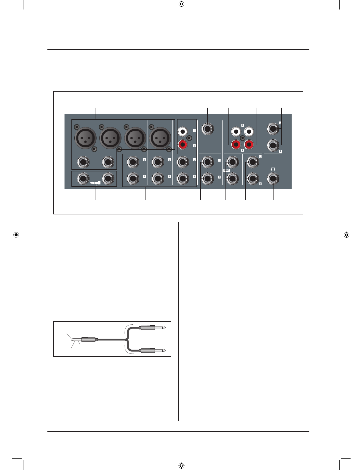
1.CHANNEL CONTROL SECTION
(1). PEAK LED INDICATOR
This LED indicators let you check the level of the signal input
to the channel. The peak indicator lights when the input signal
reaches 5dB below the channel’s clipping point. This indicator
show the level of the Post-EQ/ pre-fader signal. If the PEAK
indicator lights more than briefly on high-level transients, you
should use the GAIN control to decrease the input sensitivity
of the channel. If this dose not work, reduce the output level
of the connected source.
(2). TRIM CONTROL
According to the level of the input signal, use this knob to ad -
just the input to an appropriate level. The best balance of S/N
and dynamic range will be achieved if you adjust the TRIM
control so that the peak indicator lights occasionally. This
control adjusts the channel’s mic input sensitivity between
-50dB and -6dB and the line input sensitivity between -30dB
and +14dB.
The mono/stereo combination input channel have a sensitivity
of +20dB to-20dB
(3). HPF(High-Pass Filter)
This switch toggles the HPF on or off. To turn the HPF on,
press the switch In ( ). The HPF cut frequencies below 75Hz
(4). 3BAND EQUALIZER CONTROLS
This is a 3-band equalizer with center frequencies, range and
type as shown below. The frequency response is flat when the
knob is in the “ 0 ”position.
CONTROL MAX.
BOOST/CUT
FREQUENCY TYPE
HIGH ±15dB 12kHz Shelving
MID ±12dB 2.5kHz Peaking
LOW ±15dB 80Hz Shelving
(5). AUX 1 CONTROLS
This knobs control the level of the signals sent to AUX 1 bus.
This control is placed before the channel volume, it will be not
affected by the channel level volume.
(6). EFX CONTROLS
This knobs control the level of the signals sent to EFX bus.
The channel signals mixed by this bus have their overall level
set by the EFX SEND Control to the EFX SEND jack on the
front panel. The EFX bus signal is also fed into the internal
digital signal processor. Since this control is placed after the
channel fader, the signal level will be affected by the channel
(7). PAN /BAL CONTROL
PAN (Mono Channel)
This control pans the channel signal across the master L and
R buses, thus determining the perceived position of the sound
from that channel in the output stereo sound field. If a PAN
control is set all the way to the left,for example, the sound
from that channel will be heard from the left speaker system
only.If it is set all the way to the right, the sound will be heard
from the right speaker system only.Intermediate settings will
cause the sound to appear at corresponding locations in the
stereo sound field.
BALANCE (Stereo Channel)
This control adjusts the balance or the L/R position of the
stereo input signal.
Turning the BALANCE control to the left of center moves the
apparent source toward the MAIN L bus,turning it to the right
moves the source toward the MAIN R bus.
(8). CHANNEL LEVEL VOLUME
This is the channels main level control. It determines the
level of the signal that is sent from the channel to the master
mixing and effect buses. It is the settings of the input channel
faders that determine the mix, or the balance of sound levels
between the instruments or other sources connected to the
inputs. When a channel is not being used, its volume should
be set at the minimum position to prevent the addition of
unwanted noise to the main program signal.
2
3
4
5
6
7
8
0 10
MONO MONO STEREO
STEREO
COMBINATION
fader setting.

5
HMM-8FX
Front Panel Controls
ON
OFF
ON
OFF
PHANTOM POWER
PROGRAM
POWER
TAPE
AUX RETURN
LEVEL
LEVEL
0
5
10
LEVEL LEVEL
0
5
10
LEVEL
EFFECTS CTRL-R/PHONES
0
5
10
MAIN L/R
R
L
SELECT
-20
-10
-7
-4
-2
0
+2
+4
+7
CLIP
0 10
5
0 10
5
PERFORMANCE
HALL REVERB
PLATE REVERB
SPRING REVERB
ECHO
FLANGE+VERB
CHORUS+VERB
ECHO+VERB
CHORUS
FLANGE
1
1.MAIN CONTROL SECTION
(1). DSP PROGRAM DISPLAY
The Program Number LED displays the number of the se-
lected effects program.
(2). DSP PROGRAM SELECT SWITCH
The program knob selects one of the 100 built-in digital effects,
for each number you select. 24 Bit Digital Effects processor
with high quality, studio grade effects like Delay, Chorus and
Reverb.
(3). DSP ON/ OFF SWITCH
This switch turns the internal digital effect on/off.
(4). EFX RTN VOLUME
Adjust the level of the signal sent from the internal digital ef-
fect to the main bus.
(5). CTRL ROOM /PHONES CONTROL
Controls the level of the signal output to the PHONES jack
and the CTRL ROOM L and R jacks.
(6). MAIN L/R MASTER VOLUME
This volume faders adjust the final level of the combined signals
from all channels.
(7). STEREO RETURN CONTROL
Adjust the level of the mixed L/R signal sent from the RETURN
jack (L (MONO) and R) to the Main L/R bus.
(8). TAPE IN CONTROL
This control adjusts the level of the playback signal that is
inserted to the master mixing bus from the TAPE IN RCA jacks
on the top panel.
(9). OUTPUT LEVEL METER
A vertical row of ten LED show the continuous output level of
main Output L/R.
This type of display is free from over shoot problem of me-
chanical meters and is highly visible under poor lighting condi-
tions. The 0 LED means an output level of +4dB for +4dB
output (that’s the rated level).
(10). POWER INDICATOR
This indicator lights when the power switch is turned on.
(11). PHANTOM POWER SWITCH
This switch toggles phantom power on or off.If you set the switch
on, the mixer supplies power to all channels that provide XLR
mic input jacks. Set this switch on when using one or more
condenser microphones.
2
3
4
5
6 7
8
9
10
11
12
When this switch is on, the mixer supplies DC +48V
power to pins 2 and 3 of all XLR-type MIC INPUT
jacks.
Be sure to leave this switch off ( ) if you do not need
phantom power.
When pressed the switch on ( ), be sure that only con
-
denser mics are connected to the XLR input jacks.
Note, however, that the switch may be left on without
problem when connecting to balanced dynamic
microphones.
To avoid damage to speakers, be sure to turn off
amplifier (or powered speakers) before turning this
switch on or off. We also recommend that you turn all
out controls ( MAIN L/R CTRL-R / phones , etc).
to minimum settings before operating the switch, to
avoid risk of loud noises that could cause hearing loss
or device damage.
(12). PHANTOM POWER INDICATOR
This indicator lights when the phantom power switch is turned
on.
NOTE:
*
*
*
8 CH MIXING CONSOLE
HMM-8FX

6
HMM-8FX
(1). Channel Input Jacks
MIC JACKS
A 3-pin XLR-type connector is used for balanced low imped-
ance microphone inputs.(1: sleeve, 2: hot, 3:cold)
BALANCED LINE IN JACKS
A standard 1/4” phone jack is used for balanced or unbal-
anced line level signals. Examples of line level signals include
most electronic keyboards, synthesizers, turn-tables(with
appropriate pre-amps), tape decks and the line outputs from
other mixers.
(2). CHANNEL INSERT I/O JACK
These are input/output jacks located between the head-ampli-
fier and the high pass filte r.
These jacks allow you to own graphic equalizers, compres-
sors, noise filters, or other devices.
1. INPUT/OUTPUT CONNECTORS
Front Panel Controls
MAIN OUTPUT
AUX
FOOT SWITCH
LINE
INSERT
1
MIC
LINE 7
LINE 8
7 / 8
LINE
INSERT
2
MIC
LINE 3
LINE 4
3 / 4
MIC
LINE 5
LINE 6
5 / 6
MIC
TAPE IN REC OUT
LINE 7
LINE 8
EFX
HEADPHONE
CONTROL ROOM
MONOMONO MONO AUX
RETURN
OUT IN
1
2 3 4 7 9 11
5 6 108
Tip:Output(Send to external device)
Sleeve:Ground
Ring:Input(Return from external device)
(3). CHANNEL INPUT JACKS
These are unbalanced stereo line input jacks. Two jack types
are provided phone type and RCA pin type.
(4). RETURN L (MONO), R Jack
These are unbalanced 1/4” phone-type line input jacks. The
signal received by these jacks is sent to the MAIN bus and
AUX bus. These jacks are typically used to receive a return
signal from an external effect (reverb, delay, etc.)
NOTE:These jacks can also be used as an auxiliary stereo
input. If you connect to the L (MONO) jack only, the mixer
will recognize the signal as monaural and will propagate the
identical signal on both L and R jacks
(5). TAPE IN JACKS
These RCA pin jacks input a stereo sound source. Use these
jacks when you want to connect a CD or DAT directly to the
mixer for monitoring.
NOTE:You can adjust the signal level using the TAPE IN
control in MAIN control section.
(6). REC OUT JACKS
The REC OUT jacks send the pre-fader signal from the master
bus for recording by the tape deck.
(7). SEND JACKS
* AUX
These are unbalanced phone jacks-type output jack.
This jack output the signal form AUX bus, respectively.You use
this jack, for example, to connect to an effector or to a cue box
or other such monitoring system.
* EFX
These are unbalanced phone jacks-type output jack that output
the signal form the EFFECT bus.
You use this jack, for example, to connect to an external effector
(8). FOOT SWITCH JACK
This phone input jack can connect to the foot switch.With the
foot switch, you can use your foot to toggle the digital effects
ON and OFF
502-M822-2107_Manual_01.indd 6 2006/8/22 ¤W¤È 09:36:07

7
HMM-8FX
Front Panel Controls
(9). MAIN L/R OUTPUT JACKS
These jacks deliver stereo output of the mixer signal. You use
these jacks, for example, to connect to the power amplifier
driving your main speakers. You also use these jacks when
you wish to record the signal utilizing the level control applied
by the main volume in the main Control section.
(10). CONTROL ROOM OUTPUT JACKS
Use these stereo phone-type output jacks to connect to your
monitor system.
NOTE:The main output siguals also route to these facks
contvoleel by the CTRL-R / phones volume.
The main output siguals also route to these facks
contvoleel by the CTRL-R / phones volume.
(11). PHONES JACK
Connect for headphones. This is stereo phone-type output
jack.
(1/4" Phone 3 Section Connector)
( O )
(1/4" Phone 2 Section Connector)
( X )
NOTE:
502-M822-2107_Manual_01.indd 7 2006/8/22 ¤W¤È 09:36:07

8
HMM-8FX
1. AC ADAPTOR IN CONNECTOR
Connects to the included power adaptor.
NOTE:Use only the adaptor included with
this mixer. Use of a different adaptor may result in fire or
electric shock.
2. POWER SWITCH
Use this switch to turn mixer power to ON.
Rear Panel Controls
Rear Panel Controls
21
MADE IN CHINA
POWERAC ADAPTOR IN
ON
OFF
8 CH MIXING CONSOLE
HMM-8FX

9
HMM-8FX
Points to Remember
Points to Remember
- In all cases, use good quality twin screened audio cable. Check for instability at the output.
- Always connect both conductors at both ends, and ensure that the screen is only connected at one end.
- Do not disconnect the mains earth from each piece of equipment. This is needed to provided both safety and screen
returns to the system star point.
- Equipment which has balanced inputs and outputs may need to be electrically isolated from the equipment rack
and/or other equipment, to avoid earth loops.
It is important to remember that all equipment which is connected to the mains it a potential source of hum and inter-
ference and may radiate both electrostatic or electromagnetic radiation. In addition, the mains will also act as a carrier
for many forms of RF interference generated by electric motors, air-conditioning units, thyristor light dimmers etc.
Unless the earth system is clean, all attempts to improve hum noise levels will be futile. In extreme cases there will be
no alternative but to provide a completely separate and independent ‘technical earth’ to replace the incoming ‘noisy
earth’. However, always consult your local electricity
supply authority to ensure that safety regulations are not being infringed.
Insert Points
A
mp/Line Input
Headphones
Unbalanced
Input/Output
AUX Send
Ring
Ring
Tip
Tip
Sleeve
Sleeve
Send
Return
Screen
Hot (positive)
Cold (negative)
Screen
Left Signal
Right Signal
Ground
Signal
Ground
3 Pole (Stereo) Jack
2 Pole (Mono) Jack
Ring TipSleeve
TipSeeve
2
1
3
Balanced Input
Hot (positive)
Hot (positive)
Sleeve
Screen
Cold (negative)
Cold (negative)
LEEM products are wired to reflect accepted wiring practices used throughout the world.
Balanced XLR connectors are wired as described:
Pin #1 Shield
Pin #2 Positive
Pine #3 Negative
Balanced 1/4” TRS connectors are wired as described:
Tip is Positive
Ring is Negative
Sleeve is Shield
Connections

10
HMM-8FX
Connections
CONNECTOR AND CABLE CONFIGURATIONS
2
3
1
T R S
2
3
1
2
3
1
(XLR)
(XLR)
White(Red)/HIGH
A. XLR**
B. TRS PHONE
Black/LOW
Shield/GND
White(Red)/HIGH Black/LOW
Shield/GND
T S
TTSS
2
3
1
(XLR)
(Standard Phone)
D. STANDARD
PHONE
E. SHIELD/GND
PHONE
White(Red)/HIGH Black/LOW
Shield/GND
White(Black)/HIGH
Shield/GND
T S
2
3
1
(XLR)
C. STANDARD
PHONE
White(Red)/HIGH Black/LOW
Shield/GND
Floating or Balanced
low impedance: most
professional equipment
line in and line out,
microphones.
Unbalanced
low impedance: some
professional equipment
and microphones.
Unbalanced
high impedance: most
hi-fi equipment.
Unbalanced
high impedance: most
hi-fi equipment.
REMOTE DEVICE REMOTE SIDE OF CABLE
DESCRIPTION CABLE (Connector Type)
Connector and cable configurations recommended for use with the HMM-8FX
These cables are based on the use of auxiliary equipment that is isolated from the AC power mains.
502-M822-2107_Manual_01.indd 10 2006/8/22 ¤W¤È 09:36:08

11
HMM-8FX Applications
Applications
Setup Procedure
MAIN OUTPUT
AUX
FOOT SWITCH
LINE
INSERT
1
MIC
LINE 7
LINE 8
7 / 8
LINE
INSERT
2
MIC
LINE 3
LINE 4
3 / 4
MIC
LINE 5
LINE 6
5 / 6
MIC
TAPE IN REC OUT
LINE 7
LINE 8
EFX
HEADPHONE
CONTROL ROOM
MONOMONO MONO AUX
RETURN
OUT IN
Microphone
Guitar
Effector
Powered Monitor
Speakers
Foot Switch
Sound Source(CD,MD,DAT,
Cassette,Video etc.)
Sound Source(CD,MD,DAT,
Cassette,Video etc.)
Master Recorder(MD,DAT.)
Synthesizer
MTR
Rhythm Machine
COMPACT DISC PLAYER
PROGRAM EJECT
POWER
REPEAT SKIP FWD
MIN MAX
PLAY/PAUSE LEVELSTOP
REW
COMPACT DISC PLAYER
PROGRAM EJECT
POWER
REPEAT SKIP FWD
MIN MAX
PLAY/PAUSE LEVEL
STOP
REW
COMPACT DISC PLAYER
PROGRAM EJECT
POWER
REPEAT SKIP FWD
MIN MAX
PLAY/PAUSE LEVELSTOP
REW
Before connecting to microphones and instruments, be sure that all devices are turned off. Also be sure that all of the
mixer’s channel fader and master control faders are set all the way down.
For each connection, connect one end of the cable to the relevant microphone or instrument and connect the other end to
the appropriate input jack on the mixer.
NOTE: Where an input channel provides both a MIC INPUT jack and a LINE INPUT jack, you may use either one of these
jack but you may not use both at the same time. Please connect to only one of these jacks on each channel.
To avoid causing damage to speaker, power up the devices in the following order: Peripheral devices
→ mixer →power amps (or powered speakers).
NOTE: When shutting the system down, turn off the power in the opposite order: Power amps (powered speakers) →
mixer → Peripheral devices.
1.
2.
3.
Home Recording

12
HMM-8FX
Block diagrams
Block Diagrams

13
HMM-8FX Specifications
Specifications
*0dB=0.775Vrms, 0dBV=1VRMS
-General Specifications
Maximum Output Level (0.5%
T.H.D at 1kHz)
+20dB(MAIN L/R), +20dB( AUX1,EFX, CTR L ROOM)
+20dB(INSE RT) More than 100mW(HEADPHONES) @33Ω
T.H.D <0.1% @+14dB 20Hz ~ 20kHz (MAIN L/R, AUX SEND,EFX SEND CTR L ROOM)
Frequency Response 20Hz ~ 20kHz, +1/-2dB (MIX L/R, AUX SEND,EFX SEND CTR L ROOM)
Hum and Noise ( A verage,
20kHz LPF Rs=150Ω)
-127dB equivalent input noise, -95dB residual noise (MAIN L/R, AUX /EFX SEND, CTR L ROOM
OUT), -88dB (MAIN L/R, A L T 3/4, AUX/EFX send, CTR L ROOM OUT) * Master fader at nominal
level and all channel fader Minimum.
Maximum Voltage Gain
66dB MIC IN TO Main L/R, 60dB MIC IN TO AUX 1, 66dB MIC IN TO EFX(REV)
76dB MIC IN TO CONTRO L ROOM L/R, 58.2dB MIC IN TO REC L/R, 46dB LINE IN TO MAIN L/R
46dB LINE IN TO AUX 1, 46dB LINE IN TO EFX (REV)
56dB LINE IN TO CONTRO L ROOM L/R, 36dB S T IN TO MAIN L/R
6dB AUX RETURN IN TO MAIN L/R, 16dB TAPE IN TO MAIN L/R
Crosstalk (at 1kHz) -70dB between input channels, -70dB between input/output channels
Gain Control
(mono Input Channel) 44dB Variable (-50dB ~ -6dB), (-30dB ~ +14dB)
Gain Control(mono/stereo
combination Input ch) 40dB Variable (-20dB ~ +20dB)
Input Channel Equalization HIGH: 12kHz shelving, MID : 2.5kHz peaking LO W : 80Hz shelving * Turnover/roll o f f frequencies:
located 3dB below maximum boost/cut
LED Meters 10-Segment LEDx2 MAIN L/R,
Internal Digital Effect 100 selectable presets
FOO T switch (ON/OFF)
Channel Indicators Peak: An indicator for each channel turns on when the pre-channel fader signal is 5dB below clip -
ping.
Phantom Power +48V DC
USA / Canada 120Vac / 60Hz / PA-M822 25W
England / Australia 240Vac / 50Hz / PA-M822 25W
Korea 220Vac / 60Hz / PA-M1224 40W
Europe 230Vac / 50Hz / PA-M822 25W
Power Source/Power Con-
sumption
Weight 2.4kg
Dimensions ( W x D x H )mm 295 x 249 x 75
* Specifications and design subject to change without notice for improvements.
502-M822-2107_Manual_01.indd 13 2006/8/22 ¤W¤È 09:36:09

14
HMM-8FX
Specifications
Specifications
Input Connector Input
Impedance
Nominal
Impedance
Rated
Input Level Connector Type
CH Mic 4kΩ 50 ~ 600Ω -50dB XLR 3-31 Type Balanced
CH Line 10kΩ 600Ω -30dB Phone Jack (TRS) T = Hot R =
Cold S = GND
Stereo Input Mic 3kΩ 600Ω -44dB XLR 3-31 Type Balanced
Stereo Input Line 5kΩ 600Ω -20dB Unbalanced Phone Jack
Aux Return Insert Input 10kΩ 600Ω +4dB Unbalanced Phone Jack
Mono Channel Insert Input 10kΩ 600Ω 0dB Phone Jack (TRS) T = Out R =
In S = GND
Tape In 10kΩ 600Ω -10dBV RCA pin Jack
-INPUT
Output Connector Output
Impedance
Nominal
Impedance
Rated Output
Level Connector type
MAIN 75Ω 10KΩ +4dB Unbalanced Phone Jack
CTRL Room Out 75Ω 10KΩ +4dB Unbalanced Phone Jack
Aux/ Efx Send 75Ω 600Ω +4dB Unbalanced Phone Jack
Mono channel insert output 100Ω 10kΩ 0dB Phone Jack (TRS) T = Out R =
In S = GND
Rec Out 600Ω 10kΩ -10dBV RCA pin Jack
Phones Out 100Ω 33Ω 3mW Stereo Phone Jack
-OUTPUT
* Specifications and design subject to change without notice for improvements.
502-M822-2107_Manual_01.indd 14 2006/8/22 ¤W¤È 09:36:09

15
HMM-8FX
Service
Procedures
Take steps to insure the problem is not related to operator error or other products within the system. Infor-
mation provided in the troubleshooting portion of this manual may help with this process. Once it is certain
that the problem is related to the product contact your warranty provider as described in the warranty sec-
tion of this manual.
Schematic
A Schematic is available by contacting your warranty provider.
Parts List
A Parts List is available by contacting your warranty provider.
Variations
Products supplied through legitimate sources are compatible with local AC power requirements.
Options
No optional items are available for this product.
Warranty terms and conditions vary by country and may not be the same for all products. Terms and con-
ditions of warranty for a given product may be determined first by locating the appropriate country which
the product was purchased in, then by locating the product type.
To obtain specific warranty information and available service locations contact LEEM directly or the author-
ized LEEM Distributor for your specific country or region.
Variations and Options
Warranty
Service

16
HMM-8FX

17
HMM-8FX

www.leem.co.kr
Table of contents
Other Leem Music Mixer manuals
Popular Music Mixer manuals by other brands

Studiomaster
Studiomaster Platinum Basic MKI instruction manual

SEIKAKU
SEIKAKU 8/10 channel mixing console user manual

Peavey
Peavey CD Mix 7032A Guide d'utilisation

Peavey
Peavey XR 1204 manual

Topp Music Gear
Topp Music Gear TPM4200FX MKII V2 user manual

Synergy Global Technology
Synergy Global Technology LCD1U17-35 user manual