Lega TRIPHASE IN MONOPHASE OUT Series Specification sheet

OPERATING AND INSTALLATION MANUAL FOR
TRIPHASE IN MONOPHASE OUT SERIES
UNINTERRUPTIBLE POWER SYSTEMS
Company
:
LEGA ENERJİ ELEKTRONİK SAN. VE TİC. LTD. ŞTİ.
Addres
:
Y.Dudullu Mah. Cumhuriyet Cad. No: 13 Ümraniye / İstanbul / TURKEY
Tel
:
+90 216 533 09 02 (pbx)
Fax
:
+90 216 533 15 61
General e-mail
:
info@legaelektronik.com
Sales
:
export@legaelektronik.com
Technical Service
:
service@legaelektronik.com

1

2
1. Safety Instructions
1.1 UPS Safety Instructions
●Before applying the UPS system, Please read through all safety information and operating instructions
carefully. It’s recommended to save this manual properly for future reading.
●Do not install the UPS system near the water or in moist environments.
●Do not install the UPS system where it would be exposed to direct sunlight or near the heater.
●Place the UPS staying away from the wall for some distances, ensure enough space on each side of UPS,
do not block ventilation holes in the UPS housing. Install it by following the instructions in the manual.
●Please do not open the UPS case as you will, there is a high risk of electric shocks inside.
●Do not connect to the equipment like hair dryer or electric heater, to ensure the safety for the UPS.
●Do not use liquid extinguisher if there is a fire, a dry powder extinguisher is recommended.
Attention:
UPS has high voltage inside, for personal safety, please do not repair by yourself. If any questions, please
contact local service center or dealer.
1.2 Battery safety instructions
●Battery life cycle will be shortened as environment temperature rise. Replacing battery periodically can help
to keep UPS in normal state and assure backup time required.
●Battery replacement should be done by authorized technician. If you want to replace the battery cable,
please purchase it from our local service center or distributors to avoid fever and lighter which can cause
fire from inadequate power capacity.
●Batteries may cause electric shocks and have a high short-circuit current, for human being safety, please
follow the specifications as below when replace the batteries:
A. Remove wristwatches, rings and other metal objects
B. Use only tools with insulated grips and handles
C. Wear insulated shoes and gloves
D. Do not put the metal tools or parts on the battery
E. Before disconnecting the terminals on battery, please cut off all the loads to battery first.
●Do not dispose of the batteries with fire so as to avoid explosion.
●Don’t open the battery, electrolyte inside will do harm to eyes and skin. Please use plenty of clean water to
wash if touching and go to see a doctor.
●Do not connect the positive pole and negative pole directly, otherwise it cause electric shocks or will be on
fire.
●The battery circuit is not isolated from the input voltage, high voltage may occur between the battery
terminals and ground, before touching, please verify no voltage is present.
2. Features
2.1 Unpacking inspection
●Open the UPS package, please check the enclosed accessories including user manual, RS232
communication cable, USB cable and CD-ROM.
●Check the UPS if anything damaged in transport. If find something damaged or parts missing, do not power
on, please turn to the carrier and dealer.
●To determine whether this UPS is the model you want to buy. Check the model name showed both on the
front panel and rear panel of UPS to confirm.

3
Model
Type
LEGA 3106
6KVA Standard model
LEGA 3106L
6KVA Long backup model
LEGA 3110
10KVA Standard model
LEGA 3110L
10KVA Long backup model
LEGA 3115L
15KVA Long backup model
LEGA 3120L
20KVA Long backup model
Note:
Please save the packaging box and packaging materials for future transport use. As a heavy product, please
transit the UPS with care.
2.2 UPS rear panel view
USB
EPO
RS232
PARALLEL PORT
INTELLIGENTSLOT
BAT_NTC
EPO
RS232 USB
Parallel
Port
Input
Breaker
Intelligent
Slot
BAT_NTC
Fan
Manual
Bypass
Switch
Terminal
Block
USB
INTELLIGENTSLOT
PARALLEL PORT
EPO
RS232
BAT_NTC
INPUTBREAKER
ON OFF
WARNING
HIGHLEAKAGECURRENT
EARTHCONNECTIONESSENTIAL
BEFORECONNECTING SUPPLY
DO NOTOPEN EXCEPT
QUALIFIEDTECHNICIAN
Input
Breaker
USB
Parallel
Port
Intelligent
Slot
BAT_NTC
RS232
EPO
Manual
Bypass
Switch
Fan
Terminal
Block
INPUTBREAKER
ON
OFF
WARNING
HIGHLEAKAGECURRENT
EARTHCONNECTIONESSENTIAL
BEFORECONNECTING SUPPLY
DO NOTOPEN EXCEPT
QUALIFIEDTECHNICIAN
PARALLEL PORT BAT_NTC
RS232
USB
EPO
INTELLIGENTSLOT
RS232
EPO
USB
Parallel
Port
Intellengent
Slot
BAT_NTC
Input
Breaker
Battery
Breaker
Ext.Battery
Manual
Bypass
Switch
Fan
Terminal
Block
PARALLEL PORT
USB
EPO
RS232
INTELLIGENTSLOT
DO NOTOPEN EXCEPT
QUALIFIEDTECHNICIAN
-
+-
+
EXT.BATTERY
WARNING
HIGHLEAKAGECURRENT
EARTHCONNECTIONESSENTIAL
BEFORECONNECTING SUPPLY
ON
INPUT
BREAKER BATTERY
BREAKER
ON
BAT_NTC
a. 6KVA &10KVA Long back up b. 15KVA &20KVA Long back up c .6KVA & 10KVA Standard type
Note: Due to the technology upgrading and development, goods and diagrams might have some differences.
3. Installation instructions
3.1 Attention items of installation
●The UPS installation environment must be with good ventilation, away from water, flammable gases and
corrosive entities.
●Do not lie down the UPS against the wall so that front and side panel air intake hole, rear panel air outtake
hole will be unobstructed.
●The peripheral environment temperature around the UPS should be within 0 ℃~ 40 ℃.
● If dismantling the machine at low temperatures, there may be condensation droplets, users can not install
or operate it before UPS completely got dry both inside and outside, otherwise there will be danger of
electric shocks.
● Place the UPS near the mains socket so that can cut off ACmains without any delay at any emergent case.
●Make sure the load connect to the UPS is off when users connect the load to UPS, and then turn on the load
one by one later.

4
●Please connect the UPS with the socket which is over-current protected. Do not connect the UPS with the
socket which rated current is less than the Maximum input current of the UPS.
●All the power socket should be configured with earthing device for safety.
●UPS could be electrified or powered no matter the input power cable is tied or not, even when the UPS is off.
The only way to cut off the output is switching off the UPS and disconnecting the mains power supply.
●For all standard type UPS, it is advised to charge the battery over 8 hours before used. Once the AC mains
power energizes the UPS, it will automatically charge the battery. Without prior charging, UPS output
remains as usual but with shorter back-up time than normal.
●When connected to motor, display equipment, laser printer etc, UPS power selection should be based on
the startup power of the load which is usually twice as rated power.
●When wiring, please ensure input cables and output cables are connected firmly.
●If install a leakage current protective switch, please install it on output cable.
●For LEGA31 6-20K Series UPS, before installing, prepare wires for terminal block of the UPS based on the
following tables.
Model
Wiring spec
Three-phase
Input
Single-phase
Input
Output
Battery
Non-isolated
Neutral
Ground
6KVA
6mm2
6mm2
6mm2
6mm2
6mm2
6mm2
6KVA L
6mm2
6mm2
6mm2
6mm2
6mm2
6mm2
10KVA
10mm2
10mm2
10mm2
10mm2
10mm2
10mm2
10KVA L
10mm2
10mm2
10mm2
10mm2
10mm2
10mm2
15KVA L
16mm2
16mm2
16mm2
16mm2
16mm2
16mm2
20KVA L
20mm2
20mm2
20mm2
20mm2
20mm2
20mm2
Note: When connecting, please make sure to connect input cables and output cables with terminals firmly.
When the input is three-phase, if the UPS is working on Bypass mode, the total current goes through phase R,
so the line widths of phase R must be the same as output. When the input is single-phase, before doing input
connection, users have to use two short wires to connect R&S and S&T.
3.2 Output connection
Output connection is configured with terminal blocks. Make sure the mains wire and breakers in the building
are enough for the rated capacity of UPS to avoid the hazards of electric shock or fire.
Note: Do not use the wall receptacle as the input power source for the UPS, which rated current is less than
the UPS’s maximum input current. Otherwise the receptacle may be burned and destroyed.
L N
OUTPUT
INPUT
A B CN++ --
BATTERY
L N
OUTPUT
INPUT
A B CN
a. 6KVA &10KVA Long back up terminal blocks b. 6KVA &10KVA Standard type terminal blocks
++ --
OUTPUT
BATTERY
INPUT
A B CN NL

5
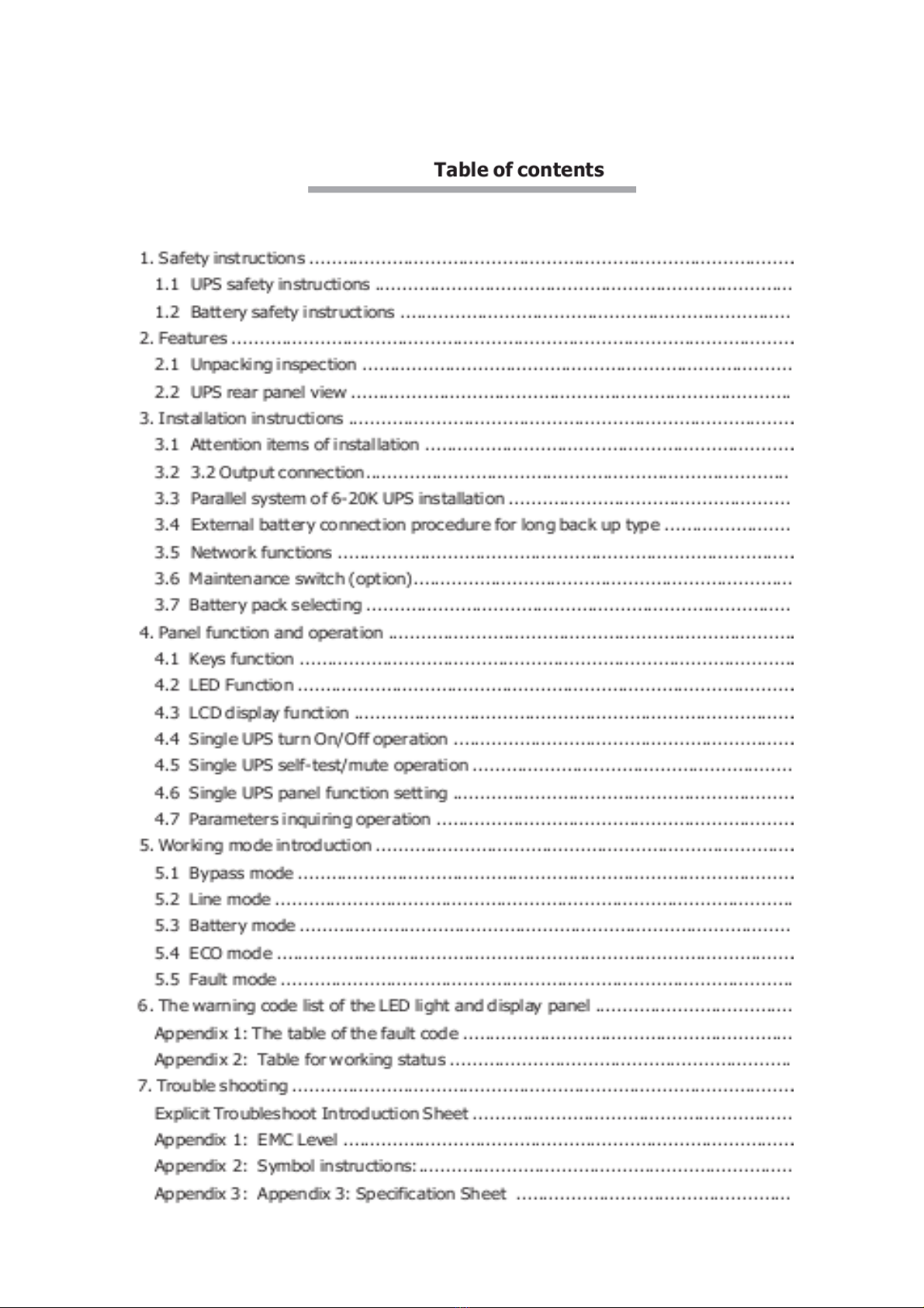
c. 15KVA &20KVA terminal blocks
3.3 Parallel system of 6-20K UPS installation
Only 6-20K UPS and containing parallel ports can do parallel operation, other types is not supported.
N+X parallel structure is the most reliable power supply structure at present, N stands for the minimum
number of UPS for the load, X stands for the number of redundant UPS,X absolutely means how many UPS
could be malfunctioning at the same time and the parallel UPS system is still steady. The larger X is, the
system is more reliable. N+X is the best method for high reliability. Just install a little more simple accessories,
at most 8 UPS could work together to form a flexible parallel system.
This structure of power supply system increases the power safety and reliability. For example, two single
UPS make up a parallel system to load averagely, when one is malfunctioning, another one can take all the
load independently. It allows isolation repairs for malfunctioning UPS, and according to users own different
requirements, every single UPS could install manual maintenance bypass switch.
3.3.1 Parallel system installation
The function of parallel operation is an optional function of UPS, users can purchase parallel function parts
(including parallel card and parallel wire) and contact service personnel to install. At most 8 UPS work
together by using parallel wires to form a flexible parallel system. Each UPS should be equipped individual
battery pack.
>Parallel system installation requirement:
●Install parallel wire, users need to purchase a specific parallel wire from our company, it’s not recommended
to use other type parallel wires. There are 2m length and 5m length to be chosen.
●Prepare wires for terminal block of the UPS based on the wiring spec table above in attention items.
●Each UPS input wiring please comply with the requirements of single UPS wiring.
●Every UPS is recommended to connect together to one common utility power terminal block.
●The output cables of each UPS are recommended to connect together on a common terminal block, then
output to the load.
●Each UPS should be equipped individual battery pack.
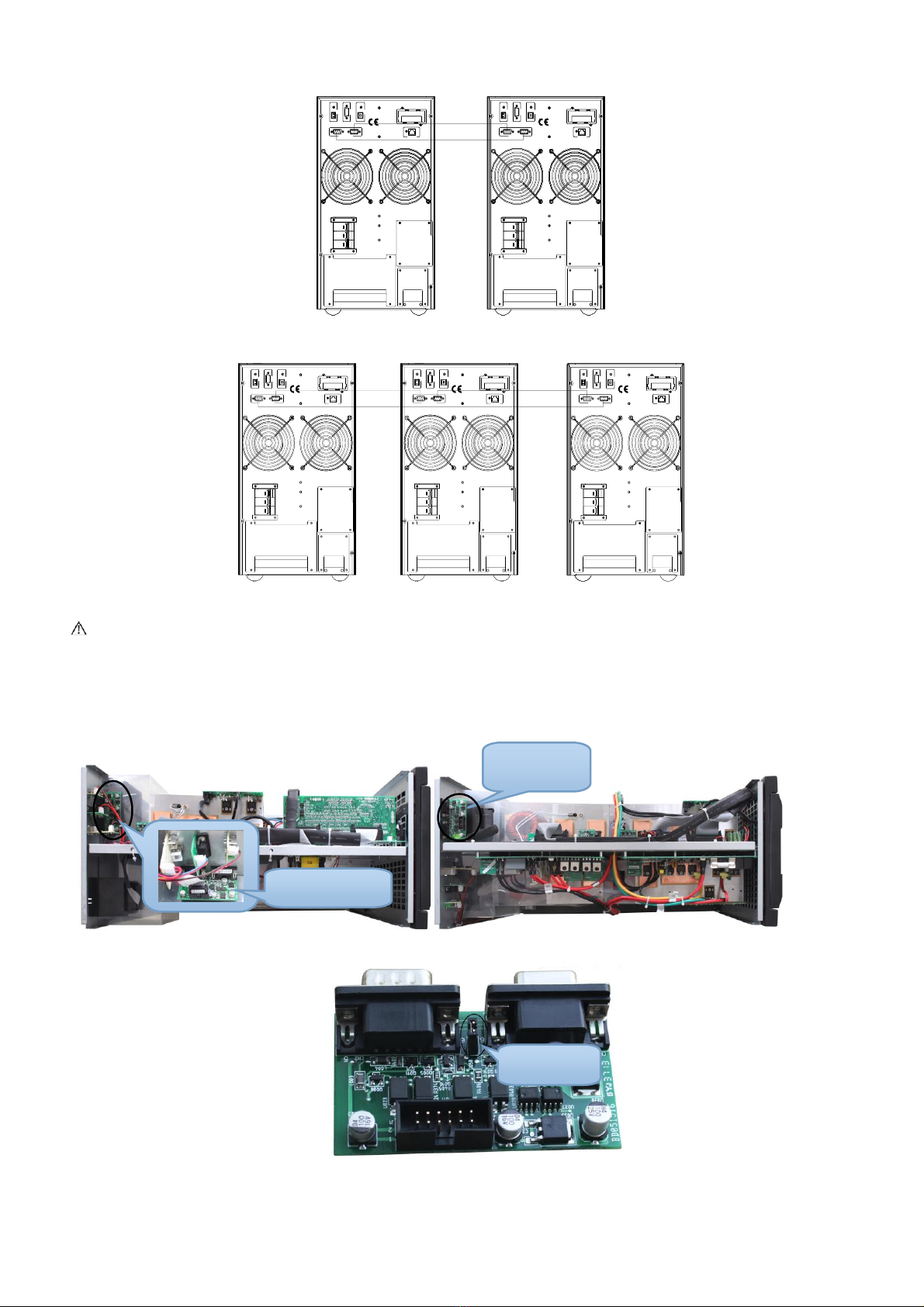
●Wiring installation for parallel UPS system please refer to the wiring diagrams are given below, switches of
6KVA should withstand more than 50A/250VAC, and switches of 10KVA should withstand more than
80A/250VAC, and switches of 15KVA should withstand more than 100A/250VAC, and switches of 20KVA
should withstand more than125A/250VAC.
●Output wiring length requirements: when the distance between the load and each UPS is less than 20
meters, the length difference of cables to the load should be less than 20%; when the distance between the
load and each UPS is more than 20 meters, the length difference of cables to the load should be less than
10%.
>Installation procedure:
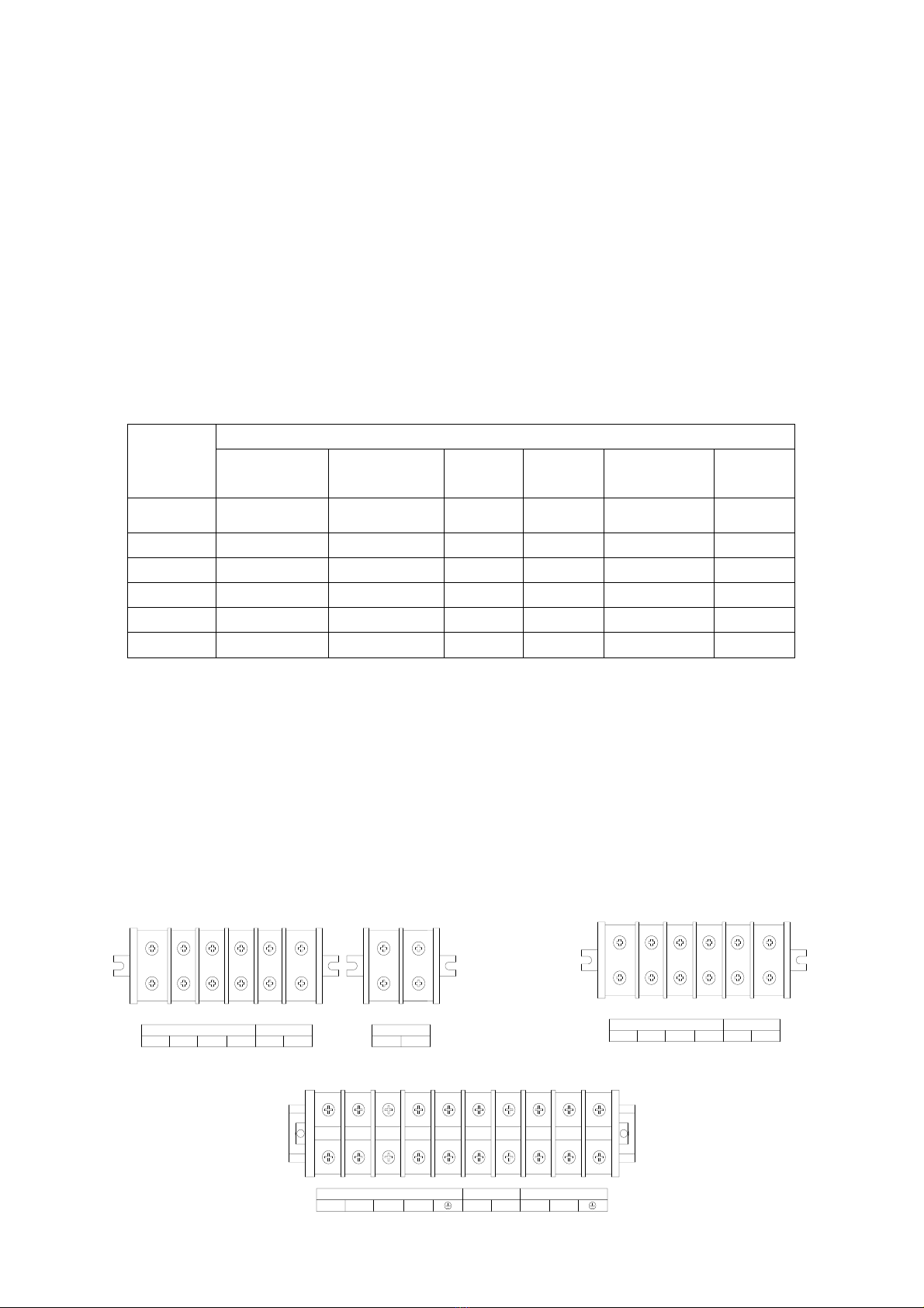
①Install parallel wires. Two UPS to form an UPS parallel system, in order to ensure the reliability of the
parallel system, there is only one way to wire two UPS, use two parallel wires to connect two UPS like the
diagram showing below, connection looks like a circle. If three or more than three UPS are needed, the
connection is similar, you can refer to the diagram as below. How many UPS unit, how many parallel wires
you need.

6
DO NOTOPEN EXCEPT
QUALIFIED TECHNICIAN DO NOTOPEN EXCEPT
QUALIFIED TECHNICIAN
USB
EPO
RS232
PARALLEL PORT
INTELLIGENT SLOT
BAT_NTC
ON
USB
EPO
RS232
PARALLEL PORT
INTELLIGENT SLOT
BAT_NTC
ON
USB
INTELLIGENT SLOT
PARALLEL PORT
EPO
RS232
BAT_NTC
INPUTBREAKER
ON OFF
WARNING
HIGHLEAKAGECURRENT
EARTHCONNECTIONESSENTIAL
BEFORECONNECTINGSUPPLY
USB
INTELLIGENT SLOT
PARALLEL PORT
EPO
RS232
BAT_NTC
INPUTBREAKER
ON OFF
WARNING
HIGHLEAKAGECURRENT
EARTHCONNECTIONESSENTIAL
BEFORECONNECTINGSUPPLY
Parallel system of two UPS wiring
HIGHLEAKAGECURRENT
EARTHCONNECTIONESSENTIAL
BEFORE CONNECTINGSUPPLY
USB
EPO
RS232
PARALLEL PORT
INTELLIGENTSLOT
BAT_NTC
USB
EPO
RS232
PARALLEL PORT
INTELLIGENTSLOT
BAT_NTC
USB
EPO
RS232
PARALLEL PORT
INTELLIGENTSLOT
BAT_NTC
USB
INTELLIGENTSLOT
PARALLEL PORT
EPO
RS232
BAT_NTC
INPUTBREAKER
ON OFF
WARNING
HIGHLEAKAGECURRENT
EARTHCONNECTIONESSENTIAL
BEFORE CONNECTINGSUPPLY
USB
INTELLIGENTSLOT
PARALLEL PORT
EPO
RS232
BAT_NTC
INPUTBREAKER
ON OFF
WARNING
HIGHLEAKAGECURRENT
EARTHCONNECTIONESSENTIAL
BEFORE CONNECTINGSUPPLY
USB
INTELLIGENTSLOT
PARALLEL PORT
EPO
RS232
BAT_NTC
INPUTBREAKER
ON OFF
WARNING
HIGHLEAKAGECURRENT
EARTHCONNECTIONESSENTIAL
BEFORE CONNECTINGSUPPLY
DO NOTOPEN EXCEPT
QUALIFIEDTECHNICIAN DO NOTOPEN EXCEPT
QUALIFIEDTECHNICIAN
Parallel system of three UPS wiring
Caution: For three UPS parallel system or more than three unites system type, please remove the short
pin CN3 on the parallel card as following pictures, Only keep the first unit and the last unit shot pin(CN3)
connected and remove the rest ones. Open the UPS cover, find the parallel card, it’s installed on the rear
panel. Take off the short pin CN3, then screw the cover back. It’s advisable to contact to local dealer to
operate, if you have to operate by yourself, please be sure that you have cut off all the electrical connection,
be careful the electric shocks from the UPS inside.
6KVA &10KVA Parallel Card 15KVA &20KVA Parallel Card
②Connect output cables of all UPS together to a common terminal block.
Parallel Card
Short Pin
Parallel Card

7
③Connect input cables of all UPS together to one common utility power terminal block.
I nput common t ermi nal bl ock
Uti l i ty power suppl y
Output common t ermi nal bl ock
Load Load Load Load ...
Parallel UPS system view
INPUT BAT1 BAT2
OUTPUT
RSTNLNBAT+ BAT- RSTNLNBAT+ BAT-
Wiring diagram for two UPS parallel system
INPUT BAT1 BAT2
R S TNLNBAT+ BAT- RSTNLNBAT+ BAT-
BAT3
OUTPUT
RSTNLNBAT+ BAT-
Wiring diagram for thee UPS parallel system
④If the UPS is the standard type, each UPS has batteries inside already. If the UPS is the long-run type,
each UPS should be equipped a individual battery pack.
⑤After installation, check all the wiring carefully, be sure to confirm correct, then can operate the system.

8
3.3.2 Parallel system operation and maintenance
General operation of parallel system, please refer to the operation instruction of single UPS. Before starting
the system, need to set up different ID for each UPS, specific settings please refer to the instruction of ID
setting which is given in single UPS panel function setting.
>Turn on the parallel system
● Start the system with mains power: After inputting the mains power,turn on any one UPS of system, others
will start by themself at same time. All UPS will enter into Line mode.
●Start the system without mains power: Make sure the battery pack is connected well and the breaker is in
“ON” position. There are two ways to start the UPS parallel system without utility power supply:
A: Press the key on each UPS, make each LCD of each UPS light up, then turn on any one UPS of
system, others will start by themself at same time. All UPS will enter into BAT mode.
B: Turn on UPS one by one.
>Turn off the parallel system
Hold on the OFF KEY of any one UPS of system for more than 4 seconds, it would turn off the whole parallel
system. Hold on the OFF KEY of any one UPS of system for more than 1 second(less than 4 seconds), it
would turn off single UPS you choose, of course if you need to turn on it again or turn on any other single
UPS of the system, just press ON KEY of that UPS to start it.
>Parallel system maintenance
●Parallel system maintenance please follow the maintenance of single UPS.
●If one UPS of parallel system is malfunctioning, first of all, turn off the malfunctioning UPS, then cut off the
input power to the faulty UPS and disconnect the output of faulty UPS to the parallel system, make sure that
there is no electrical connection with malfunctioning UPS, after all of those, it’s safe to do operation.
3.4 External battery connection procedure for long back up type
●For different UPS type, users are instructed to configure different battery voltage as below sheet. More or
less units are forbidden, or else something abnormal or faulty will appear.
Type
Battery Quantity
(unit)
Battery Voltage
(volt)
6KVA
16/20
192V/240V
10KVA
16/20
192V/240V
15KVA
16/20
192V/240V
20KVA
16/20
192V/240V
Note: there are two battery pack options for UPS, 16 units and 20 units. Users can choose the different
battery pack voltage in accordance with different requirements. The default units of batteries to UPS is 16,
and users can not connect 16 batteries to UPS if the UPS should be connected 20 units. Please strictly follow
the procedure of batteries connection, or will get electric shocks.
1. Set the battery switch at ‘OFF’ position, then install batteries in series.
2. Connecting the cables to batteries firstly, or you may get electric shocks if you connect the cables to UPS
firstly. You’d better connect the red cable to battery positive pole ‘+’, black to negative pole ‘-’, so that it would
be much easier to distinguish.

9
3. Select proper cables to connect the batteries and UPS is very important, and there should be a switch
connected between the battery pack and UPS.
4. Finally, without any load, set on the battery switch which is connected between the UPS and the battery
pack, so that UPS can get connected to batteries, then switch in the mains power, after doing all of those, the
batteries will be charged by the UPS automatically.
BAT
+-
BAT
+-BAT
+-BAT
+-
Positive Negative
16/20PCS
To UPS terminal blocks
Battery
Breaker
3.5 Network functions
3.5.1 Communication port
Users could monitor the UPS system through the communication port such as standard RS232 port and
standard USB port with computer. With a communication wire to connect UPS and computer, could simply
achieve UPS management.
☆RS232 port:
Foot
1
2
3
4
5
6
7
8
9
Explanation
empty
send
receive
empty
ground
empty
empty
empty
empty
☆USB port:
Foot
1
2
3
4
Explanation
+5V
date+
date-
GND
3.5.2 EPO port
EPO is short for Emergency Power Off, EPO port is on rear panel of UPS, it’s green, in some emergent cases,
users could cut off the output of UPS immediately by operating EPO port. Wiring diagram as below:

10
Normally, pin1 and pin2 are connected so that the machine can be working normally. When some
emergencies happen, and when users do have to cut off the output, just need to disconnect the connection
between pin1 and pin2, or there is a anther useful simple way is pulling it out.
3.5.3 Intelligent card (option)
This series High frequency online UPS supply a intelligent slot on rear panel, it’s for SNMP card, dry contact
and USB card, users could insert any type intelligent card from those three into it to monitor and manager the
UPS. You don’t have to turn off the UPS when you install the intelligent card. Procedure as following:
●Fist of all, remove the intelligent slot cover;
●Then insert the intelligent card(SNMP card, dry contact or USB card);
●Last, screw the intelligent card back.
> SNMP card (option)
SNMP card on UPS is compatible with the most software, hardware and network operating system, it is a
network management of UPS, with this function, UPS can login on internet , which can supply information of
UPS status and input power, and even possible to control UPS via net management system.
> Dry contact card (option)
Insert the dry contact card into the intelligent slot, it’s another type function of intelligent monitoring.
Foot
Definition
PIN1
ON:UPS is malfunctioning
PIN2
ON:Alarm(system failure)
PIN3
Ground
PIN4
Remote shutdown
PIN5
Common
PIN6
ON:Bypass mode
PIN7
ON:Battery low
PIN8
ON:Inverter mode;
OFF:Bypass mode
PIN9
ON:No AC power in
> RS485 card (option)
RS485 card is also designed for this series UPS, A(+) and B(-) on the right are the output of RS485.
All above, for more information, please contact to the local dealer.

11
3.6 Maintenance switch (option)
UPS with maintenance switch(option) can be maintained online. Open the maintenance bypass switch cover
you can see a maintenance switch if the UPS has this function.
When you need to maintain or repair the UPS online, follow the procedure as below:
●Open the maintenance bypass switch cover, UPS will transfer to BYPASS mode automatically;
●Set the switch at “BYPASS” position;
●Now you can maintain or repair the UPS;
●After finishing the maintenance operation, set the switch back to “UPS” position, and put the cover back.
Complete all the steps above, you are done the maintenance.
3.7 Battery pack selecting
There are two options of battery group quantity for users to choose, 16 units and 20 units. The default
quantity is 16 units, but this series UPS are also allowed to connect with 20 units batteries. When users want
to apply 20 units batteries group for this series UPS, need to open the UPS case and find the control board
and the charger, then operate the short pins on control board and charger board.
Control board Charger board
Battery group
Operation
16 units batteries
A. Remove the short pin(J16) off the control board;
B. Insert the short pin(middle of CN7) of the charger board.
20 units batteries
A. Remove the short pin(middle of CN7) of the charger board;
B. Insert the short pin(J16) of the control board.
Note: for long-run type UPS, there are two chargers, users have to operate two charger board.
4. Panel function and operation
The operation is simple, operators onlyneed to read the manual and follow the operation instructions listed in
this manual without any special training.
4.1 Keys function
Short pin
Short pin

12
※ON KEY ( + )
Press and hold the two keys for more than half a second to turn on the UPS.
※OFF KEY ( + )
Press and hold the two keys for more than half a second to turn off the UPS.
※TEST/MUTE KEY ( + )
Press and hold the two keys for more than 1 second in Line mode or ECO mode or CUCF mode: UPS runs
the self-test function.
Press and hold the two keys for more than 1 second in battery mode: UPS runs the mute function.
※INQUIRING KEY ( , )
Non-function setting mode:
Press and hold or for more than half a second (less than 2 seconds): display the items orderly.
Press and hold for more than 2 seconds: Circularly and orderly display the items every 2 seconds,
when press and hold the key for some time again, it will turn to output status.
Function setting mode:
Press and hold the key or for more than half a second (less than 2 seconds): Select the set option.
※FUNCTION SETTING KEY
Non-function setting mode:
Press and hold the key for more than 2 seconds: Function setting interface.
Function setting mode:
Press and hold the key for more than half a second (less than 2 seconds): Enter the function setting option.
Press and hold the key for more than 2 seconds: exit from this function setting interface.
4.2 LED Function

13
Number
LED
Explanation
①
Inverter LED
Inverter green LED is on: UPS is normally powered by Line mode or ECO
mode or BAT mode.
②
Battery LED
Battery yellow LED is on: Battery mode.
③
Bypass LED
Bypass yellow LED is on: Bypass mode or ECO mode, etc.
④
Warning LED
Warning red LED is on: UPS fault. For example: Overload beyond the allowed
time, inverter fault, BUS fault, over temperature fault, etc
PS: LED display detail in different mode is listed at the back.
4.3 LCD display function
LCD displays as following figure.
※Icon display area:
A. The top diagram is for load and battery capacity indication, each grid of which represents 25%. When UPS
is over load, the load light will blink the same as the battery light blink when the capacity of battery get low
or battery disconnected.
B. The fan icon is for fan working indication; when fan normally runs, the icon will display rotation; if the fan is
not connected or faulty, the icon blinks;
C. Press the mute button under the battery mode, buzzer icon will blink; it will disappear in other cases.
D. Fault icon will be on when UPS is in fault mode, otherwise it will not.
※Digital display area:
A. Under none setting mode, it will display UPS output information when UPS normally runs in AC
mode; other information like input, battery, load and temperature will be showed after pressing the inquiring
key; Fault code will be told in fault mode.
B. Under setting mode, users could adjust different output voltage, activate ECO mode, activate CUCF mode,
select an ID number and so on by operating function setting key and inquiring keys.
※Mode display area:
A. This area will display the power capacity of the machine after starting the UPS within 20 seconds.
B. After over 20 seconds, this area will display the working mode of the machine. Such as STDBY(standby
Mode), BYPASS(Bypass Mode), LINE(AC Mode), BAT(Battery Mode), BATT(Battery Self Test Mode ),
ECO(Economic mode), SHUTDN(Shutdown mode), CUCF(Constant Voltage and Constant Frequency
Digital display area
Working mode
display area
Icon display area

14
Mode).
4.4 Single UPS turn On/Off operation
4.4.1 Turn on operation
> Turn on the UPS on line mode
①Once mains power is plugged in, the UPS will charge the battery, at the moment, LCD shows that the output
voltage is 0, whichmeans UPS has no output as default condition. If it is expected to have output of bypass,
you can set the BPS “ON” by LCD setting menu.
②Press and hold the ON key for more than half a second to start the UPS, then it will start the inverter.
③Once started, the UPS will perform a self-test function, and LED will light and go off circularly and orderly.
When self-test finishes, it will come to online mode, the corresponding LED lights, UPS is working in line
mode.
> Turn on the UPS by DC without mains power
①When main power is disconnected, press and hold the ON key for more than half a second to start UPS.
②The operation of UPS in the process of start is almost the same as that when mains power is on. After the
self-test finishes, the corresponding LED lights and UPS are working in battery mode.
4.4.2 Turn off operation
> Turn off the UPS in line mode
①Press and hold the OFF key for more than half a second to turn off the UPS and inverter.
②After UPS shutting down, LED goes out and there is no output. If output is needed, you can set BPS “ON”
on LCD setting menu.
> Turn off the UPS in DC mode without mains power
①Press and hold the OFF key for more than half a second to turn off the UPS.
②When turning off the UPS, it will do self-test first. LED lights go out circularly and orderly until there is no
display on the panel.
4.5 Single UPS self-test/mute test operation
①When UPS is in LINE Mode, press and hold the self-test/mute keyfor more than 1 second, LED light will go
off circularly and orderly. UPS comes to self-test mode and tests its status. It will exit automatically after
finishing test.
②When UPS is in BAT Mode, press and hold the self-test/mute key for more than 1 second, the buzzer stops
beeping. If you press and hold the self-test/mute key for one more second, it will restart to beep again.
4.6 Single UPS panel function setting
UPS has setting function. It can run the setting in any mode. After setting, it will become effective at once
when meets some standards. The set information can be saved only when the battery connected and
normally turning off the UPS.
4.6.1 ECO mode setting
①Enter the setting interface. Press and hold the function setting key for more than 2 seconds, then come
to setting interface, press and hold the inquiring key ( , ) for more than half a second(less than 2

15
seconds), select the function setting, choose output voltage setting interface, at the moment, the letters
“ECO” will flash.
②Enter the ECO setting interface. Press and hold the function setting key for more than half a
second(less than 2 seconds), then come to setting interface of ECO, at this time, the letters “ECO” will not
flash any more. The “ON” (or OFF) will flash. Press and hold the inquiring key ( ,) for more than
half a second (less than 2 seconds) to determine whether the ECO function is used or not. If used, the
corresponding word is “ON”, if not, the word is “OFF”. It can be determined by yourself.
③Confirm the ECO selecting interface.After selecting ON or OFF, press and hold the function setting
key for more than half a second (less than 2 seconds). Now, the ECO setting function is completed
and the “ON” or “OFF” will light without flash.
④Exit from the setting interface. Press and hold function setting key for more than 2 seconds, exit from
the setting interface and return to main interface.
4.6.2 Input methods setting
①Enter the setting interface. Press and hold the function setting key for more than 2 seconds, then come
to setting interface, press and hold the inquiring key ( , ) for more than half a second(less than 2
seconds), select the function setting, choose output voltage setting interface, at the moment, the letters
“IPP” will flash.
②Enter the IPP setting interface. Press and hold the function setting key for more than half a second(less
than 2 seconds), then come to setting interface of IPP, at this time, the letters “IPP” will not flash any more,
the numerical value next to the IPP will flash. Press and hold the inquiring key ( , ) for more than
half a second (less than 2 seconds) to select the numerical value. There are two Input methods, the value
‘1’ means single phase input, the value ‘3’ means three phase input. The default input method is single
phase.
③Confirm the IPP selecting interface.After selecting input method, press and hold the function setting
key for more than half a second (less than 2 seconds). Now, the IPPsetting function is completed and

16
the value next to IPP will light without flash.
④Exit from the setting interface. Press and hold function setting key for more than 2 seconds, exit from
the setting interface and return to main interface.
4.6.3 Output voltage setting
①Enter the setting interface. Press and hold the function setting key for more than 2 seconds, then come
to setting interface, press and hold the inquiring key ( , ) for more than half a second(less than 2
seconds), select the function setting, choose output voltage setting interface, at the moment, the letters
“OPU” will flash.
②Enter the output voltage setting interface. Press and hold the function setting key for more than half a
second(less than 2 seconds), then come to setting interface of output voltage OPU, at this time, the letters
“OPU” will not flash any more. The numerical value next to the OPU will flash. Press and hold the inquiring
key ( , ) for more than half a second (less than 2 seconds), select the numerical value in
accordance with “OPU” function. The provided voltages are 208V, 220V, 230V, 240V, you can choose
anyone by yourself (The default value is 220V).
③Confirm the output voltage setting interface. After selecting numerical value, press and hold the function
setting for more than half a second (less than 2 seconds). Now, the OPU setting function is completed
and the numerical value will light without flash.
④Exit from the setting interface. Press and hold function setting key for more than half a second (less
than 2 seconds), exit from the setting interface and return to main interface.
4.6.4 Low battery voltage shutdown point setting
①Enter the setting interface. Press and hold the function setting key for more than 2 seconds, then
come to setting interface, Press and hold the inquiring key ( , ) for more than half a second(less
than 2 seconds), select the function setting, choose battery voltage setting interface, at the moment, the
letters “bat” will flash.
②Enter the battery voltage selecting interface. Press and hold the function setting key for more than half
a second(less than 2 seconds), then come to setting interface of battery voltage, this time, the numerical
value will flash. Press and hold the inquiring key ( , )for more than half a second (less than 2
seconds), select the numerical value in accordance with “battery” function. The provided voltages are 10V,
10.2V, 10.5V, numbers stand for the voltage of each battery, you can choose anyone by yourself (The

17
default is 10V), anyone has been chosen, under BAT mode, UPS will shutdown when its battery voltage
achieve the voltage you chose.
③Confirm the battery voltage selecting interface. After selecting numerical value, press and hold the function
setting , for more than half a second (less than 2 seconds). Now, the battery setting function is
completed and the numerical value will light without flash.
④Exit from the setting interface. Press and hold function setting key for more than half a second (less
than 2 seconds), exit from the setting interface and return to main interface.
4.6.5 Frequency converter mode setting
①CUCF mode only can be set in STDBYmode. In STDBY mode, enter the setting interface. Press and hold
the function setting key for more than 2 seconds, then come to setting interface, Press and hold the
inquiring key ( , ) for more than half a second(less than 2 seconds), select the function setting,
choose battery voltage setting interface, at the moment, the letters “CF” will flash.
②Enter the CF setting interface. Press and hold the function setting key for more than half a second(less
than 2 seconds), then come to setting interface of CF, at this time, the letters “CF” will not flash any more.
The “ON” (or OFF) will flash. Press and hold the inquiring key ( ,) for more than half a second (less
than 2 seconds) to determine whether the CF function is used or not. If used, the corresponding word is
“ON”, if not, the word is “OFF”. It can be determined by yourself.
③Confirm the CF selecting interface.After selecting ON or OFF, press and hold the function setting key
for more than half a second (less than 2 seconds). Now, the CF setting function is completed and the “ON”
or “OFF” will light without flash.
④Exit from the setting interface. Press and hold function setting key for more than 2 seconds, exit from
the setting interface and return to main interface.
⑤After setting CF at “ON”, UPS would be back in STDBY Mode. The default value of CF is OFF.
4.6.6 Output frequency setting in CUCF mode
①Output frequency only can be set when CUCF mode is ON.

18
②In STDBY mode, enter the setting interface. Press and hold the function setting key for more than 2
seconds, then come to setting interface, Press and hold the inquiring key ( , ) for more than half a
second(less than 2 seconds), select the function setting, choose battery voltage setting interface, at the
moment, the letters “OPF” will flash.
③Enter the OPF setting interface. Press and hold the function setting key for more than half a
second(less than 2 seconds), then come to setting interface of OPF, at this time, the letters “OPF” will not
flash any more. The “OFF” (or 50HZ, 60HZ) will flash. Press and hold the inquiring key ( , ) for
more than half a second (less than 2 seconds) to determine whether the CF function is used or not. If used,
select 50HZ or 60HZ according to you. It is determined by yourself, the default value is 50HZ.
④Confirm the OPF selecting interface.After selecting 50HZ or 60HZ, press and hold the function setting
key for more than half a second (less than 2 seconds). Now, the OPF setting function is completed
and the “50HZ” or “60HZ” will light without flash.
⑤Exit from the setting interface. Press and hold function setting key for more than 2 seconds, exit from
the setting interface and return to main interface.
4.6.7 ID setting
①Enter the setting interface. Press and hold the function setting key for more than 2 seconds, then come
to setting interface, press and hold the inquiring key ( , ) for more than half a second(less than 2
seconds), select the function setting, choose output voltage setting interface, at the moment, the letters “Id”
will flash.
②Enter the output voltage setting interface. Press and hold the function setting key for more than half a
second(less than 2 seconds), then come to setting interface of ID, at this time, the letters “Id” will not flash
any more. The numerical value next to the “Id” will flash. Press and hold the inquiring key ( ,) for
more than half a second (less than 2 seconds), select the numerical value. The provided ID numbers are 1,
2, 3, 4, 5, 6, 7, 8, you can choose anyone by yourself (The default value is 1).
③Confirm the output voltage setting interface. After selecting numerical value, press and hold the function
setting for more than half a second (less than 2 seconds). Now, the ID setting function is completed
and the numerical value will light without flash.
④Exit from the setting interface. Press and hold function setting key for more than half a second (less
than 2 seconds), exit from the setting interface and return to main interface.
Note: ID only can be set before doing parallel operation.

19
4.7 Parameters inquiring operation
Press and hold the inquiring key or for more than half a second(less than 2 seconds) to inquire about
items. The inquired items include input, battery, output, load and temperature. The displayed items on LCD
screen are showed as following:
Output:Display the output voltage and output frequency of the UPS.As the following graphic shows, the
output voltage is 220V, the output frequency is 50Hz.
Load: Display the numerical value of the active power (WATT) and apparent power (VA) of the load. For
example, as the following graphics shows: the WATT of the load is 9KW, VA is 10KVA (when disconnect load,
it is a normal phenomenon to show a small numerical value of WATT and VA).
Temperature: Display the maximum temperature of the components in the UPS. As the following graphics
shows: the maximum temperature is 40℃.
This manual suits for next models
6
Table of contents
Other Lega UPS manuals
Popular UPS manuals by other brands

Oceanlife
Oceanlife Zeus 400 user manual

Online
Online HU10kVA-RACK quick start guide

Emerson
Emerson Liebert itON 1500 quick start guide

MGE UPS Systems
MGE UPS Systems Upsilon STS 800A Installation and user manual

Belkin
Belkin P73220uk user manual

Tycon Power Systems
Tycon Power Systems UPSPro UPAL48-900 manual