This func
tio
n allows ta
activate
a p
ro
gr
un ar a range of
progr
ams
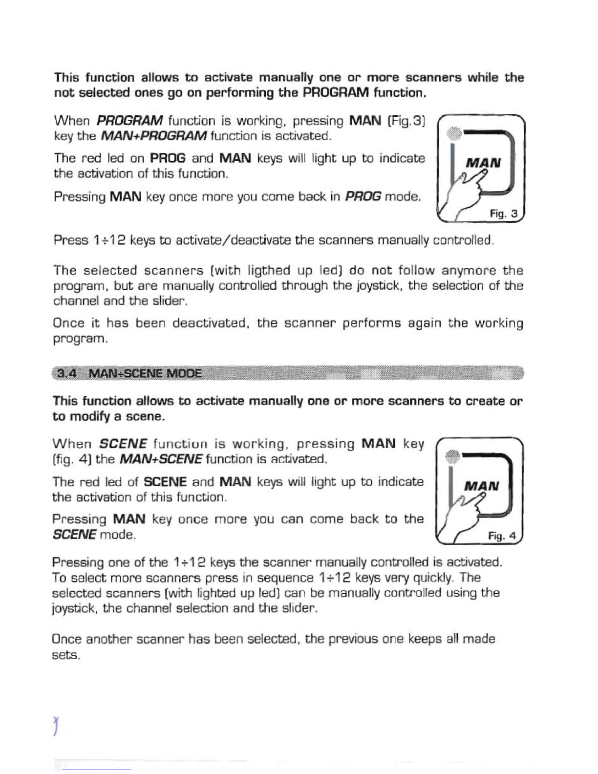
Pressing PROG key
th
ePROGRAM funct on is activated
,-
- - - -----
(F;g.1)
~
-_
The red led of PROG key will Iight up ta irdicate the actlvation
of this functian.
The
LCO
display indicates the prog
ram
VoI
lr
king
at
m
oment
.
If no pro
gram
is activated, the controlle gaes in BLACKOUT
MODE and the LeD display indicates
~B
L.
~
".
Press 1+12 keys ta activat
e/de
activate he
pr
o
gr
ams which will be
perio
rmed
in succession .
AII seleeted programs have a lighted
uţ;
led. while the active program has a
flashing led.
N.B. Each
progra
m is repeated for a nuriber of tlmes established t
hro
ugh the
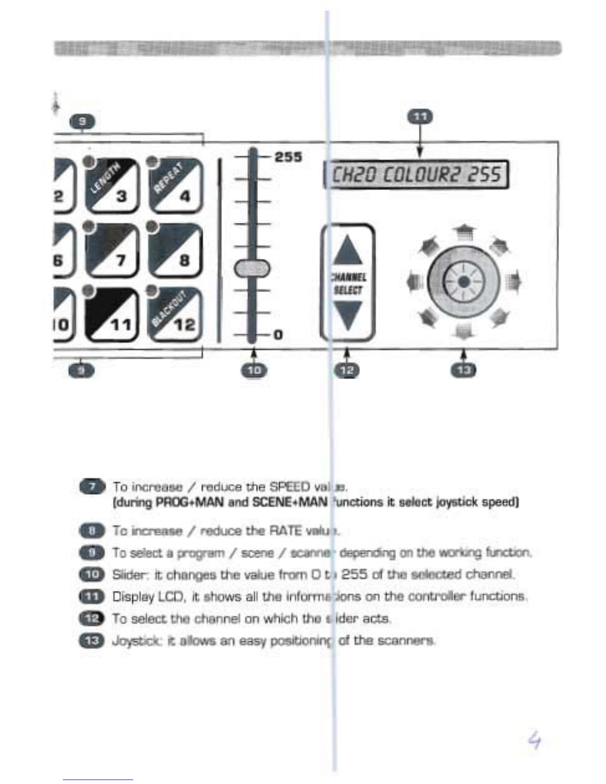
REPEAT function (see par. 5.
4]
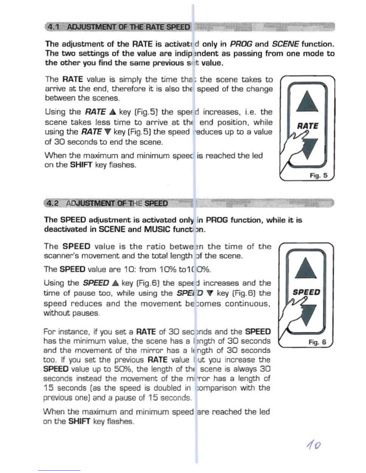
The speed of change be
tw
een the scer es can be co
ntro
lled by
RATE'"
and
RATE
't'keys (see par. 4.1J.
The relation be
tw
een the movem
ent
of 1he scanners and
the
pause between
scenes ia contr-olled by SPEEO ....ano SP
::
ED
'"
keys (see p
ar
. 4
.2
].
When the maximum ar minimum speed is
r-
lached the led of the SHIFTkey
f1ash
es.
!3.
11
; sCENEMotf
E'
''''
"~::''ţ'''~
~~
This
func
tion
allaws
ta
see one
of
the
1!scenes
of
the p
rogr
am in
ectic
n.
N.B. If no
prog
rams a
re
selec
te
d the SI:ENE fu
nctia
n is nat ac
tiv
e.
Pressing SCENE key
th
eSCENEfunctian is activated (Fig
.2
)
The
red
led of SCENE key
will
light up
ta
ind
ica
te
the ,
activation of this function. @
When yau pass f
rom
PRO
GRAM
mode to SCENE mode.
th
e
scene active in
th
at mom
ent
is seleeted.
The LCD display indica
te
s
th
e scene work n9
at
moment.
If no scene is activated . the con
tr
oller
goes
in BLACKOUT
MODE and
the
LeD display indicates
~BU
".
Press any 1+12 k
eys
to activate
/de
activl te
Iil
e scene.
The speed of change between the sceru s can be controlled by
RATE'"
and
RATE'"
(see
par
.4
.1]
.
Whenthe maximum ar minimum speed is
f"I
achcd the led of the SHIFT
key
f1ashe
s.
N.B. In
th
is funetion SPEED ... and SPEElJ ... keys
are
not activated