Color Sage CS-MC100 LED SIX BEE LIGHT User manual

Factory: 6 Floor, A Building, No.1742 Panyu North Ave,Panyu District, Guangzhou.
Office: No.34-208, Longqi Road, Qiaonan Street, Panyu District,Guangzhou.
+86-20-3110 3721
www.color-sage.com YOUTUBE FACEBOOK
CS-MC100 LED SIX BEE LIGHT
User Manual
KEEP THIS MANUAL FOR FUTURE NEEDS
1. Clean the inside and outside lens each week to avoid the weakneness of the lights
due to accumulation of dust.
2. Clean the fan each week.
3. A detailed electric check by approved electrical engineer each three month, make sure that the
circuit contacts are in good condition, prevent the poor contact of circuit from overheating.
4. Frequent cleaning. Please use a moist, lint- free cloth. Never use alcohol or solvents.
There are no serviceable parts inside the device. Please refer to the instructions under “Installation
instructions”.
Should you need any spare parts, please order genuine parts from your local dealer

*CAUTION!
Becareful with your operations.With a dangerous voltage you cansuffer a
dangerous electric shock when touching wires!
This device has left the factory in perfect condition. In order to maintain this condition and to ensure a
safe operation, it is absolutely necessary for the user to follow the safety instructions and warning
notes written in this user manual.
*IMPORTANT!
Damages caused by the disregard of this user manual are not subject to
warranty. The dealer will not accept liability for any resulting defects or
problems.
If the device has been exposed to temperature changes due to environmental changes, do not switch
it on immediately. The arising condensation could damage the device.
Leave the device switched off until it has reached room temperature.
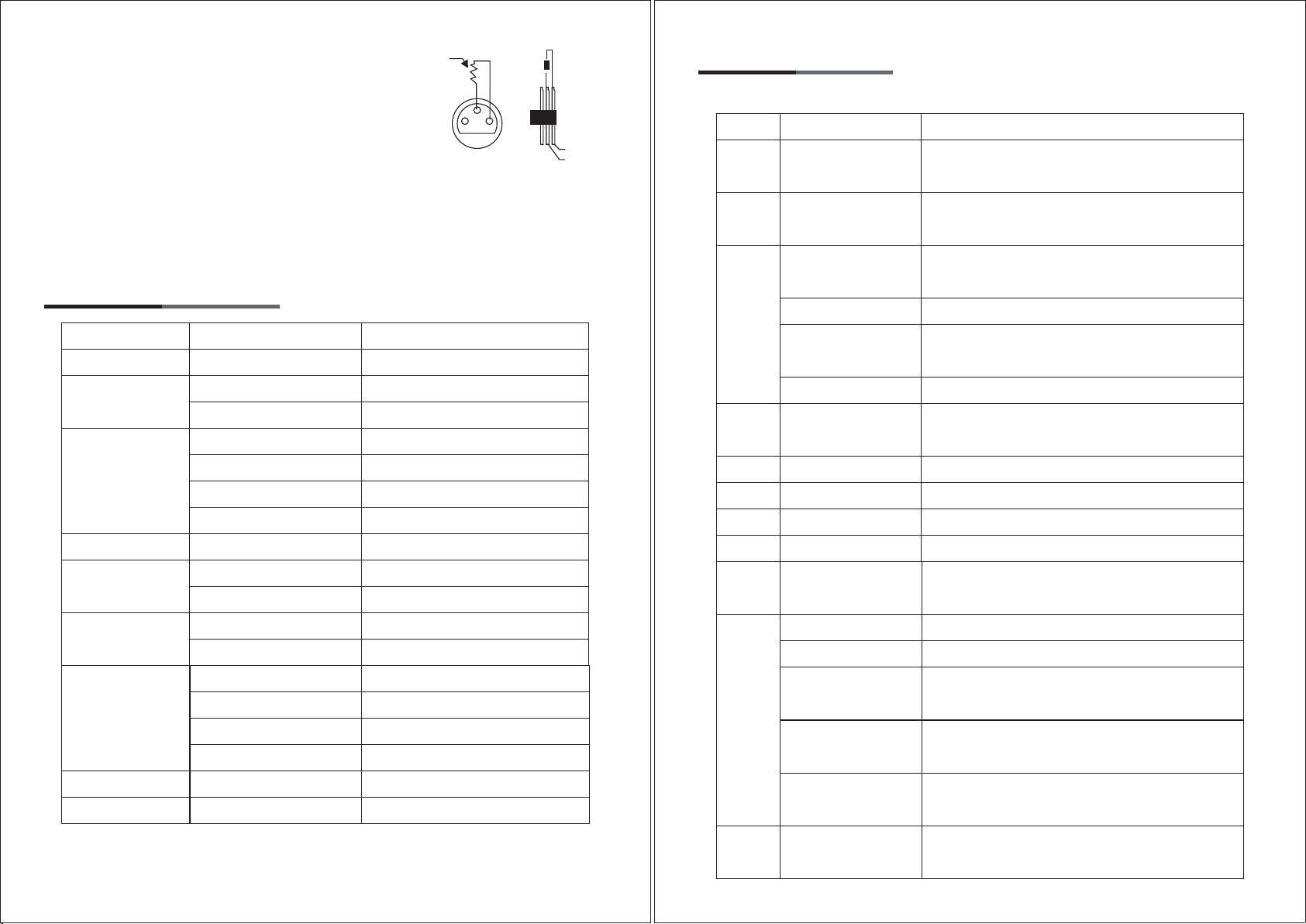
This device falls under protection-class I. Therefore it is essential that the device be earthed.
The electric connection must carry out by qualified person.
The device shall only be used with rate voltage and frequency.
Make sure that the available voltage is not higher than stated at the end of this manual.
Make sure the power cord is never crimped or damaged by sharp edges.
Always disconnect from the mains, when the device is not in use or before cleaning it.
Only handle the power cord by the plug. Never pull out the plug by tugging the power cord.
During initial start-up some smoke or smell may arise. This is a normal process and does not
necessarily mean that the device is defective, it should decrease gradually.
Please don't project the beam onto combustible substances.
Fixtures cannot be installed on combustible substances, keep more than 50cm distance with wall for
smooth air flow, so there should be no shelter for fans and ventilation for heat radiation.
If the external flexible cable or cord of this luminaire is damaged, it shall be exclusively replaced by
the manufacturer or his service agent or a similar qualified person in order to avoid a hazard.
1. SAFETY INSTRUCTIONS
01
2. UNPACKING
Thank you for choosing Color sage's CS-MC100(LED SIX BEE LIGHT). For your own safety, please
read this manual before installing the device. This manual covers the important information on
installation and applications. Please install and operate the fixture with following instructions.
Meanwhile, please keep this manual well for future needs.
This product is a mini type bee moving head.It use 2.4 inch TFT screen. It’s very convenient to
operate and scan the menu. It can record the working time and lighting hours, display the
temperature/channels data and soft information. It built-in master/salve, sound actived, auto, RDM
and DMX512.
The shell of this light is made of high quality ABS fire resistant plastics, light weight and excellent
heat dissipation.
This product is used to enliven atmosphere for family gatherings, KTV box, disco Ballroom, ballroom,
nightclub, disco, bar, mall, wedding, square, park, etc.
02
CS-MC100(LED SIX BEE LIGHT)
1pc
CS-MC100 LED SIX BEE LIGHT
User Manual
KEEP THIS MANUAL FOR FUTURE NEEDS
User Manual
1pc
Signal Cable
1pc
Power Cable
1pc
USAStandard Euro Standard UK Standard
Power Out
1pc
OPTIONAL
Safety Cable
1pc
Omega Clamp
1pc

Function:
01. Slave/Master
02. Sound actived
03. Auto
04. DMX 512
05. RDM
06. Strobe
Specifications:
LED quantities: 6*15W 4 in 1 RGBW LED
Input Voltage: AC90V-240V, 50/60HZ
Power consumption: 100W
life span: 50,000 hrs
Lens: Aspheric lens
Channel: 11CH/14CH
Beam angle: 1.5 degree
Motorized zoom: From 6 degree to 51 degree
Pan: 540 degree
Tilt: 180 degree
Rotationeffect: 360 degree rotation
Color: RGBW four in one rotation,
macro function color system
Strobe: 1-30 / sec electronic strobe and
random strobe
Display: LCD display
Material Science: ABS fire resistant plastics
Packing & weight:
Size: 220mm*220mm*230mm
Net Weight: 4.1kg
Packing: 330mm*280mm*260mm
Gross weight: 4.8kg
3. FEATURES & SPECIFICATIONS
03
CS-MC100(LED SIX BEE LIGHT) is a mini type bee moving head.
01. Don’t turn on the fixture if it’s been through severe temperature difference like after transportation
because it might damage the light due to the environment changes. So make sure to operate the
fixture until it is in normal temperature.
02. This light should be keep away from strong shaking during any transportation or movement.
03. Don’t pull up the light by only the head, or it might cause damages to the mechanical parts.
04. Don’t expose the fixture in overheat, moisture or environment with too much dust when installing
it. And don’t lay any power cables on the floor. Or it might cause electronic shock to the people.
05. Make sure the installation place is in good safety condition before installing the fixture.
06. Make sure to put the safety chain and check whether the screws are screwed properly when
installing the fixture.
07. Make sure the lens are in good condition. It’s recommended to replace the units if there are any
damages or severe scratch.
08. Make sure the fixture is operated by qualified personnel who knows the fixture before using.
09. Keep the original packages if any second shipment is needed.
10. Don’t try to change the fixtures without any instruction by the manufacturer or the appointed
repairing agencies.
11. It is not in warranty range if there are any malfunctions from not following the user manual to
operate or any illegal operation, like shock short circuit, electronic shock, lamp broke, etc.
4. OPERATION INSTRUCTIONS
04
5. INSTALLATIONS
Cautions:
For added protection mount the fixtures in areas outside walking paths, seating areas,
or in areas were the fixture might be reached by unauthorized personnel.
Before mounting the fixture to any surface, make sure that the installation area can hold a minimum
point load of 10 times the device’s weight.
230mm
220mm
150mm
200mm
230mm
180mm
220mm

Fixture installation must always be secured with a secondary safety attachment, such as an
appropriate safety cable.
Never stand directly below the device when mounting, removing, or servicing the fixture.
from a ceiling, or set on a flat level surface (see illustration below). Be sure this fixture is kept at
least 0.5m (1.5 ft) away from any flammable materials (decoration etc.).
Always use and install the supplied safety cable as a safety measure to prevent accidental damage
and/or injury in the event the clamp fails.
Mounting points:
Overhead mounting requires extensive experience, including amongst others
calculating working load limits, a fine knowledge of the installation material being used, and periodic
safety inspection of all installation material and the fixture. If you lack these qualifications, do not
attempt the installation yourself. Improper installation can result in bodily injury.
Be sure to complete all rigging and installation procedures before connecting the main power cord to
the appropriate wall outlet.
Clamp Mounting:
The product provides a unique mounting bracket assembly that integrates the
bottom of the base, the included “Omega Bracket,” and the safety cable rigging point in one unit (see
the illustration below). When mounting this fixture to truss be sure to secure an appropriately rated
clamp to the included omega bracket using a M10 screw fitted through the center hole of the “omega
bracket”. As an added safety measure be sure to attached at least one properly rated safety cable to
the fixture using on of the safety cable rigging point integrated in the base assembly
Regardless of the rigging option you choose for your , always be sure to secure your fixture with a
safety cable. The fixture provides a built-in rigging point for a safety cable on the hanging bracket as
illustrated above. Be sure to only use the designated rigging point for the safety cable and never
secure a safety cable to a carrying handle.
05
Connect the provided XLR cable to the female 3-pin XLR output of your controller and the other side
to the male 3-pin XLR input of the moving head. You can chain multiple Moving head together
through serial linking. The cable needed should be two core, screened cable with XLR input and
output connectors. Please refer to the diagram below.
DMX-512 connection with DMX terminator
*Important Notes!
Please do not link more than this Product at AC220V voltage!
6. DMX-512 CONTROL CONNECTIONS
06
Satety Clamp
Omega Bracket
Safety Cable
1/4 Turn Quick-Lock Fasteners
1/4 Turn
POWER IN
DMX IN
Signal link
Power link
POWER OUT
POWER IN
DMX OUT
DMX IN
3
2 1 1: Ground
2: Data(-)
3: Data(+)
COMMON
1
2
3
1
2
3
DMX+
DMX-
DMX512 OUT
3-PIN XLR
DMX Output
3-Pin XLR Socket
DMX Input
3-Pin XLR Socket
DMX512 IN
3-PIN XLR
1 2
3

For installations where the DMX cable has to run a long distance or
is in an electrically noisy environment, such as in a discotheque, it
is recommended to use a DMX terminator. This helps in preventing
corruption of the digital control signal by electrical noise. The DMX
terminator is simply an XLR plug with a 120 Ω resistor connected
between pins 2 and 3,which is then plugged into the output XLR
socket of the last fixture in the chain.
Please see illustrations below.
12
3
PIN3
PIN2
120Ω
7. MENU OPERATIONS
Instructions
DMX 512 address set
11 Channel
14 Channel
Console mode
Fast opperation
Slow run mode
Sound operating
Sound sensitivity
X motor forward
X motor reversal
Y motor forward
Y motor reversal
Function/Value
Address set 001-512
11
14
DMX mode
Fast mode
Slow mode
Sound mode
0-99
OFF
ON
OFF
ON
MENU
DMX set
Sound sense
Channel set
Show mode
Pan inverse
Tite inverse
0807
R 0-255
G 0-255
B 0-255
W 0-255
Yes
Yes
Default confinrm
Fixture res
White balance
Red adjustment
Green adjustment
Blue adjustment
White adjustment
Initialization factory
System reset
Instructions
Adjustmentis turned up during, down regulate
inversion
Adjustmentis turned up during, down regulate
inversion
128-191 Slow up, 191 the fastest speed
0-255 Slow up, 255 the fastest speed
R, G, B, W, always open bubble from dack to
bright
Red, moving light from dark to bright
Green, moving light from dark to bright
Blue, moving light from dark to bright
White, moving light from dark to bright
8. DMX CHANNELS
1. 11Channelmodel
Function/Value
Position offset/
0-127
Spinning/128-191
Reverse rotation
192-255
Zoom/0-255
R dimming/0-225
G dimming/0-225
B dimming/0-225
W dimming/0-225
Channel
5
6
7
8
1
2
3
4
X/0-255
Y/0-255
Tuned light/0-255
0-127 Slow up, 127 the fastest speed
192-255 Slow up, 255 the fastest speed
11-127 Slow up, 127 the fastest speed
Channel 10 speed regulating function, 0-255
Slow up, 255 the fastest speed
Color transitions
Color gradient mode 1
Color gradient mode 2
11
10
0-10
Color mixing/11-127
Color mixing mode
1/128-160
Color mixing mode
2/161-200
Color mixing mode
3/201-255
Speed regulation/
0-255
A scale of 0-255 to stroboscopic adjustment,
from slow to fast
Other channels
9Stroboscopic/0-255

09
The following points have to be considered during the inspection:
1. All screws for installing the devices or parts of the device have to be tightly connected and must
not be corroded.
2. There must not be any deformations on the housing, color lenses, fixations and installation spots
(ceiling, suspension, trussing).
3. Mechanically moved parts must not show any traces of wearing and must not rotate with
unbalances.
4. The electric power supply cables must not show any damage, material fatigue or sediments.
Further instructions depending on the installation spot and usage have to be adhered by a skilled
installer and any safety problems have to be removed
*CAUTION!
Disconnect from mains before starting maintenance operation.
In order to make the lights in good condition and extend the life time, we suggest a regular cleaning
to the lights.
9. MAINTENANCE AND CLEANING
10
2. 14Channelmodel
InstructionsFunction/Value
Channel
1
2
3
4
X/0-255
X fine-tuning/0-255
Y/0-255
Y fine-tuning/0-255
Speed/0-255
Adjustmentis turned up during, down regulate
inversion
Adjustment is turned up during 0-255, down
regulate inversion
Adjustmentis turned up during, down regulate
inversion
Adjustment is turned up during 0-255, down
regulate inversion
Slow up, 255 the fastest speed
5
6
7
12
Tuned light/0-255
Stroboscopic/0-255
0-127Slow up, 127 the fastest speed
192-255 Slow up, 255 the fastest speed
Position offset/
0-127
Spinning/128-191
Reverse rotation
192-255
Zoom/0-255
R dimming/0-225
G dimming/0-225
B dimming/0-225
W dimming/0-225
128-191 Slow up, 191 the fastest speed
0-255 Slow up, 255 the fastest speed
R, G, B, W, always open bubble from dack to
bright
Red, moving light from dark to bright
Green, moving light from dark to bright
Blue, moving light from dark to bright
White, moving light from dark to bright
A scale of 0-255 to stroboscopic adjustment,
from slow to fast
8
9
10
11
0-10
Color mixing/11-127
Color mixing mode
1/128-160
Color mixing mode
2/161-200
Color mixing mode
3/201-255
Speed regulation/
0-255
Other channels
11-127 Slow up, 127 the fastest speed
Channel 13 speed regulating function, 0-255
Slow up, 255 the fastest speed
Color transitions
Color gradient mode 1
Color gradient mode 2
13
14
InstructionsFunction/ValueChannel
Table of contents
Other Color Sage Dj Equipment manuals