LEGRAND LE06499AE Service manual

Cast Resin Transformers
Installation, use and maintenance manual
05/21-01 PC LE06499AE

2

3
Cast Resin Transformers
Installation, use and maintenance manual
Index
The supplier does not assume any responsibility for the use or inappropriate use of the products mentioned in this
manual.
This guide does not cover all the details or possible variations of the entire series of connections, installation and possible
operations. For further information or to solve specific problems that are not included in this guide, contact Legrand.
THIS ENTIRE DOCUMENT BEFORE YOU COMMENCE THE INSTALLATION.
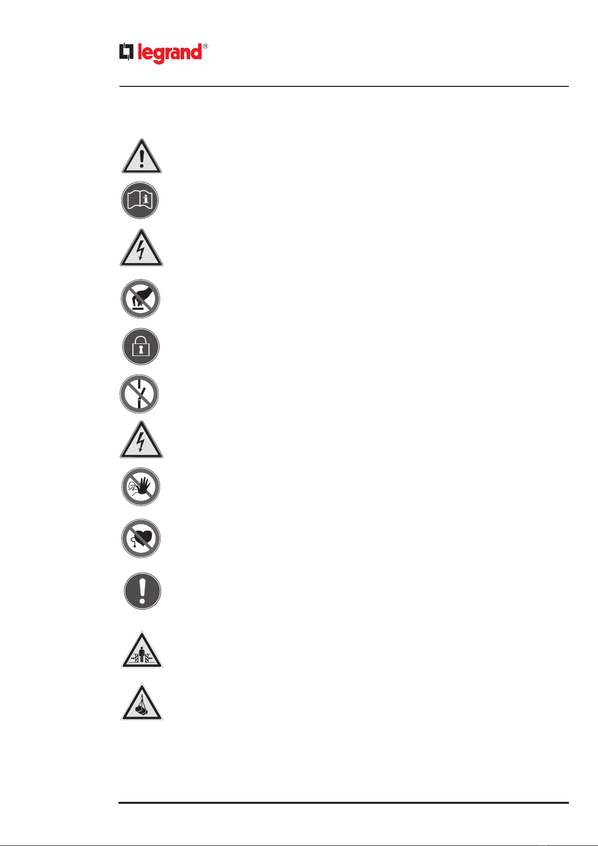
1 Safety guidelines 4
2 Reference standards 6
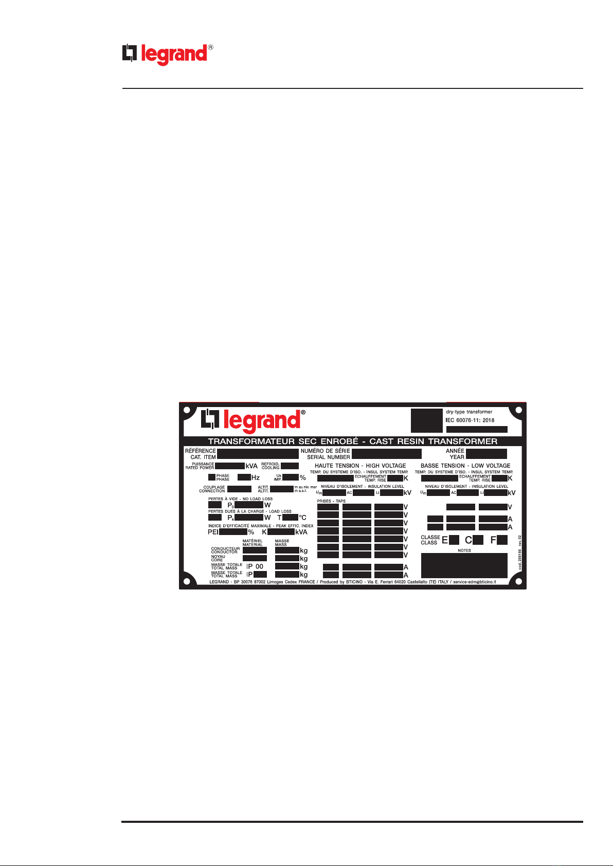
3 Rating plate 6
3.1 Conditions for the correct operation of the transformer 6
4 Transport, receipt and storage 7
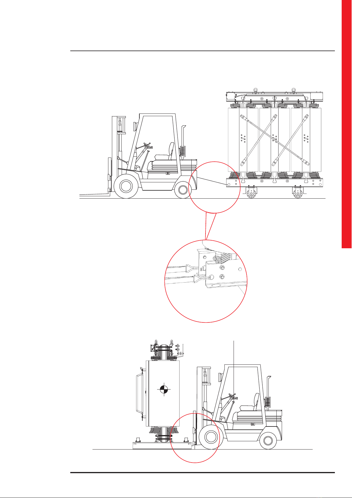
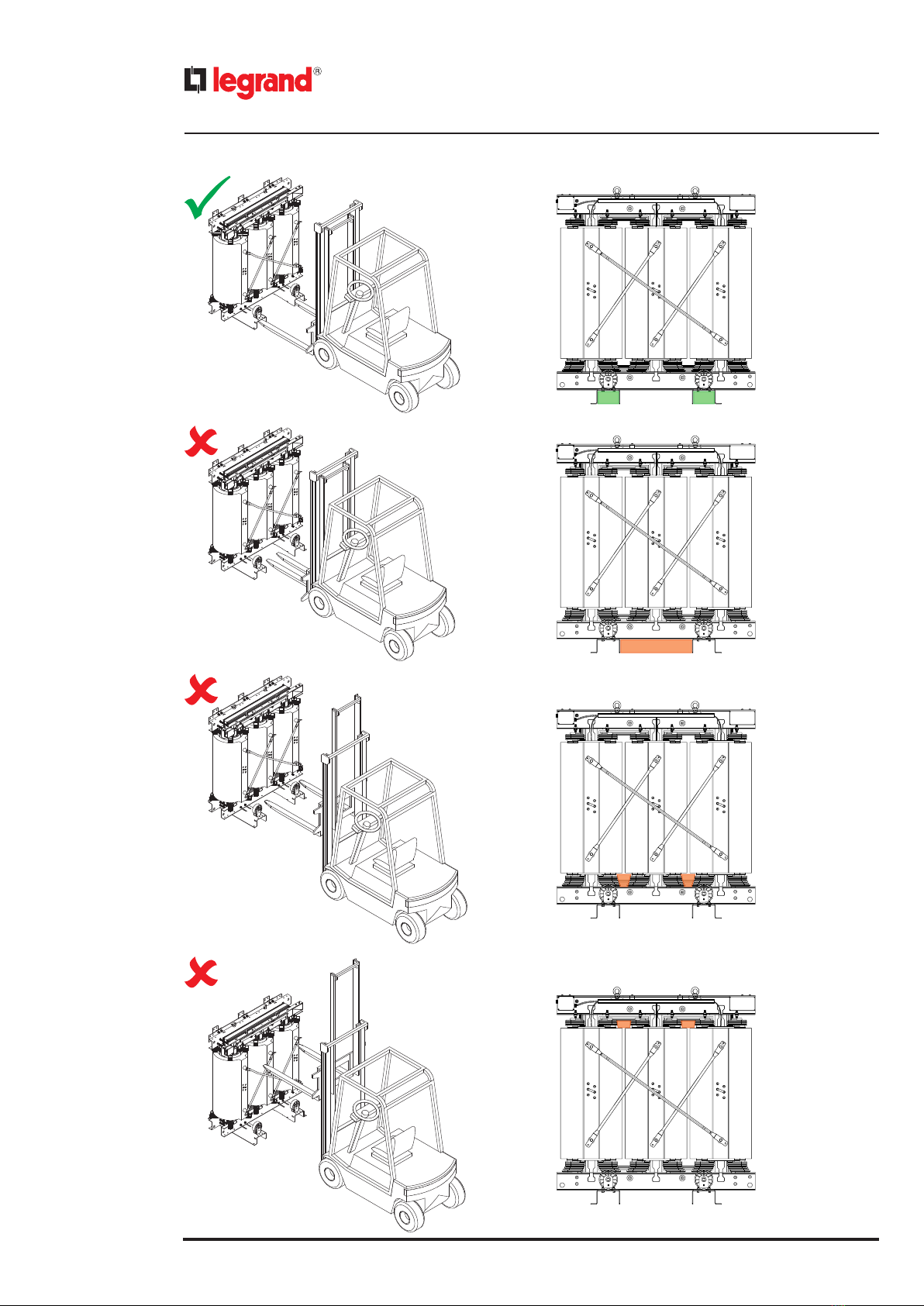
4.1
Lifting the transformer
8
4.2 Moving the transformer 11
4.3 Storing the transformer 12
5 Installation 13
5.1 Installation examples 13
5.1.1 Installation in protection enclosure 13
5.1.2 Installation without protection enclosure/box (IP00) 14
5.1.3 Examples of wrong installation 15
5.2 Connections on the Low Voltage side - LV 16
5.3 Connections on the High Voltage side - HV 16
5.4 Tightening torque for electrical and mechanical connections 17
5.5 Positioning 17
5.6 Ventilation 18
5.7 Protection against overvoltages 18
5.8 Temperature monitoring systems 19
6 Commissioning 20
6.1 Earth Connection 20
6.2 Tappings for voltage setting on HV windings 21
6.3 Cleaning 22
6.4 Measurement of windings earth resistance 22
6.5 Energising 22
7 Reception, installation and initial energising of the transformer 23
8 Maintenance 24
8.1 Indicative table on the main maintenance operations 24
8.2 Guide for trouble-shooting 26
8.3 Customer Care 26
9 Additional information 27
10 Environmental aspects 28

4
1. Safety guidelines
A cast resin transformer is an electrical equipment. It must be installed, protected and used in compliance
with the existing national and international Standards and Regulations. The possible improper installation
and use of a cast resin transformer may cause risks of electric shock or re.
Please, read this installation manually carefully before: lifting, moving or energising the transformer.
Every operation on the transformer must be performed when the transformer is not energised..
Before operating on the CRT, make sure that the transformer cannot be put under voltage without your
permission..
Do not energise the transformer before having connected the core to earth..
Do not energise the transformer before having carefully and completely inspected it.
Do not get close to the cast resin transformer before having connected the windings to earth.
Do not access the transformer operation area or remove the protection devices when the transformer is
under voltage..
Each transformer generates a magnetic eld. For this reason, any carrier of metallic devices as pacemakers
should not get closer than 3 m to an energised transformer.
This transformer must be installed according to the installation directions and preferably by a skilled and
qualied HV electrician.
Do not open, disassemble, alter or modify the transformer with the exception of special indications reported
in the Installation Manual.
All Legrand products must be opened and repaired only by personnel trained and authorized by Legrand.
Legrand is not responsible for any non-authorized opening or repair.
When moving the transformer or its components, always be aware of the risk of crushing.
When lifting the transformer, do not stand under suspended loads.

5
Cast Resin Transformers
Installation, use and maintenance manual
4
5
8
9
11
6
10
1
2
12
13
6
7
1. Low Voltage Terminal (LV)
2. Lifting eye bolt
3. Magnetic core
4. Rating plate
5. High Voltage (HV) winding
6. Horizontal movement hooking points
7. Connection earthing
8. Trolley with swivel rollers
9. Voltage switch
10. Delta connection
11. High Voltage Terminals
12. Temperature probe
13. Auxiliary circuit box for probes
3

6
IEC 60076-11 – Power transformers – Part. 11: Dry-type transformer.
IEC 60076-1 – Power transformers – Part 1: General.
IEC 60076-2 – Power transformers – Part. 2: Temperature rise.
IEC 60076-3 – Power transformers – Part 3: Insulation levels, dielectric tests and external clearances in air.
IEC 60076-5 – Power transformers – Part. 5: Ability to withstand short circuit.
IEC 60076-10 – Power transformers – Part. 10: Determination of sound levels.
IEC 60085 – Electrical insulation – Thermal evalution and designation.
IEC 60270 – High-voltage test techniques – Partial discharge measurements.
IEC 60529 – Degrees of protection provided by enclosures (IP code).
2. Reference standards
3. Rating plate
3.1 Conditions for the correct operation of the transformer
• Respect of all the instructions reported in this manual.
• Operation of the transformer in accordance with the rating plate data.
• Earth connection of the transformer with the correct terminals.
• Protection of the transformer against: chemical agents, pollution, atmospheric pollution, sun radiation, vegetation and
animals that could influence the normal operating conditions.
• Protection of the transformer against mechanical damages during installation and operation.
• Protection against overvoltages.
A rating plate showing nominal values and serial number is applied on each transformer.

7
Cast Resin Transformers
Installation, use and maintenance manual
During transport, the transformers must be adequately fixed as indicated in the explanatory images. HV and LV connec-
tions must not be stressed by the retaining straps.
4. Transport, receipt and storage
Any non-conformity must be recorded on the delivery note and notied to the forwarding agent or to Legrand.
It has to be verified that the data on the rating plate are the same data reported on shipping documents and test reports
of the transformer.
It has to be verified that each transformer is provided with contractual accessories such as rollers, temperature sensors,
control thermometer, etc. …
Once the transformer is at its destination, it is highly recommended to carefully examine it.
In particular the following details have to be verified: HV and LV terminals and connections, presence of scratches and/or
cracks on the windings of HV and their centering with respect to the windings of LV, integrity of the protection enclosure
(if present), presence of impurities, dirt, foreign body, moisture or water.

8
4.1 Lifting the transformer
Do not stand under suspended loads.
Move the transformer only in vertical position
Use all 4 eye bolts during lifting. Do not allow that the angle between the ropes to exceed 60°.The attachment point must
be at least equal to the distance between the eyebolts.
Gradually increase the tension on the lifting cables to avoid sudden shock or stress to the transformer.
If the transformer has a protective enclosure, remove the centre panel of the roof to allow the eyebolts to be attached.
max 45°

9
Cast Resin Transformers
Installation, use and maintenance manual
Lift the transformer avoiding improper lifting (that may cause it to tip over): be careful about the high centre of gravity
of the transformer.
It is forbidden to lift the transformer by inserting the forks of the forklift under the upper yoke of the core.

10

11
Cast Resin Transformers
Installation, use and maintenance manual
4.2 Moving the transformer
The transformer (with or without enclosure) must be moved
using the track or lower jokes where the proper holes are lo-
cated.
Do not move the transformers by applying force
on the windings or on their connections.
Avoid moving the transformer on sloping surfa-
ces.
It is recommended to avoid moving the tran-
sformer on the rollers more than 10 m.
Movement can be made only in two directions,
according to the rollers orientation.
Attachment points for
horizontal movement
using ropes.

12
4.3 Storing the transformer
If the transformer is not installed immediately, it has to be pro-
tected against water, dust, humidity and sunlight even if provi-
ded with enclosure.
In case of storage the packaging supplied with the transformer
must not be removed.
If the transformer has been lifted using eyebolts, restore the in-
tegrity of the packaging with adhesive tape.
The temperature during storage and installation
must not decrease below -25°C (unless otherwise
agreed order stage).
After a long storage at very low temperatures or in
an environment with high humidity, the transfor-
mer must be dried before being placed in service.

13
Cast Resin Transformers
Installation, use and maintenance manual
5.1 Installation examples
The cable connections of High and Low Voltage can be done with cables coming from the bottom or the top.
Some examples are listed below.
5.1.1 Installation in protection enclosure
5. Installation
Dry type cast resin transformers are designed for indoor installations, in a site protected from direct sunlight, in clean and
dry environments, without risk of water intrusion. Standard installation must be:
1. At a sea level height not above 1000 m
2. At a temperature of the cooling air not exceeding the following values:
a. 20 ° C yearly average
b. 30°C warmest month average
c. 40°C maximum
3. According to all other normal operating conditions as per IEC 60076-11 Standard.
During the installation refer to the safety rules existing in your country.
During the operations for the connection and installation, always protect the windings to avoid external
parts such as bolts, washers, cable parts, etc. following into the windings and jeopardizing the insulation
capability of the transformer.
BT MT
1U 1V 1W
MT
BT
1U 1V 1W
1V 1W 1U

14
5.1.2 Installation without protection enclosure/box (IP00)
Between HV and LV connections and transformers’ windings
and delta connections, the minimum distances shown in the
table must be respected.
HV and LV cables must always be supported to avoid mechani-
cal stress on the terminals.
kV D (mm)
≤ 12 ≥ 125
≤ 17,5 ≥ 170
≤ 24 ≥ 225
≤ 36 ≥ 320
HV cable
from
Sequence
of the
phases
Activities to be performed
Top U - V - W None
Bottom V - W - U Move the bolts from the top
to the bottom terminals
HV cables, even if shielded, must not pass inside delta connec-
tion on HV side.
1U 1V 1W
1U1W1V
BT MT
D
D

15
Cast Resin Transformers
Installation, use and maintenance manual
Example 1
Example 2
5.1.3 Examples of wrong installation
High voltage connection cables must not be laid inside the triangle connection and must not touch it. The
connection cables must not touch the windings, or any other active parts of the transformer.

16
5.2 Connections on the Low Voltage side - LV
LV terminals are positioned on the upper part of the transformer and they are in aluminium as standard. We recommend
to make the cable connection with tinned-copper cable terminals, connecting one or two cables in each hole.
Cu
Al
Cupal
In the case of connections with busbar it is necessary to use exible connections to mechanically isolate the transformer
from busbars.
In order to prevent corrosion caused by the direct connection between copper and aluminium, it is necessary to use Cu-
pal intermediate plates (supplied on request) when connecting untreated copper busbars to the LV aluminium terminals.
5.3 Connections on the High Voltage side - HV
The HV terminals positioned on the opposite side to the LV terminals, are made with brass bolts placed at the two ends
of the winding.
In case of connection of cables from the bottom, the upper pins can be inserted on the lower end by inverting the se-
quence of phases in accordance to the example previously reported in the gure.
Do not replace the brass bolts with bolts of a dierent material: this could alter the connection.

17
Cast Resin Transformers
Installation, use and maintenance manual
5.4 Tightening torque for electrical and mechanical connections
Tighten screws and bolts of electrical and mechanical connections in accordance with the values reported in the table: it
is recommended to re-test after a few hours of operation to eliminate the eects of any adjustments.
During the operations of clamping always use two wrenches to prevent distortion or damage.
Electrical connection [Nm]
Mechanical
connection
Screw / Bolt Steel Brass [Nm] (mm)
M 6 10 - 15 5 - 10 20 10
M 8 30 - 40 10 - 15 35 13
M 10 50 - 60 20 - 30 45 17
M 12 60 - 70 40 - 50 60 19
M 14 90 - 100 60 - 70 100 22
M 16 120 - 130 80 - 90 150 24
M 18 - - 200 27
M 20 - - 270 30
M 22 - - 360 32
M 24 - - 460 36
5.5 Positioning
Cast resin transformers do not ensure contact insulation.
It is absolutely forbidden to touch the windings while the transformer is energised.
Therefore the transformer must always be installed in a metal enclosure,inside a cage or in a room with doors enabling
access only when the transformer is de-energised.
Inside this electrical enclosure the transformer has to be positioned complying with minimal insulation distance from the
walls. They are related to the insulation class shown in the Rating plate.
kV A (mm) B (mm) C (mm)
≤ 12 ≥ 125 ≥ 60 (*)
≤ 17,5 ≥ 170 ≥ 80 (*)
≤ 24 ≥ 225 ≥ 120 (*)
≤ 36 ≥ 320 ≥ 200 (*)
C=B except when there is a voltage switch present on the
LV side whereby C = A
In order to prevent horizontal movement of the transfor-
mer the mounting direction of the wheels can be modi-
ed.
B
B
C
A

18
5.6 Ventilation
The transformer during its operation generates losses due to the passage of current through the windings and the effect
on the core of the magnetizing current. The losses, the values of which are shown on the test report, are transformed into
heat that must be dissipated from the room in which the transformer is installed to comply with the conditions of normal
use and prevent over-temperature limits being exceeded.
The room must be equipped with an opening at the bottom part S, to ensure an adequate flow of fresh air and an aper-
ture S’on the opposite wall in the high part, to extract the hot air that rises due to the chimney effect.
To determine the dimensions of the openings required use the following formulas ( valid for an annual average tempe-
rature to 20°C ).
S = 0.185 x (TL / radq(H);
S’= S x 1.15 where: S = net surface of entry in m2
S’= net surface of exit in m2
TL = sum of no-load losses and load losses expressed in kW and indicated on the test report
H = height between two opening in meter
For transformer directly fixed to the floor without rollers, it is good that they are still lifted off the ground to allow air
circulation.
If provided with protective box, the transformers must be placed no closer than 0.2 m from the surrounding walls to allow
air circulation.
In the case in which the enclosure was undersized or poorly ventilated it is advisable to install a forced ventilation system
which can ensure a flow rate of 3.5 - 4 m3 of air per minute for each kW of losses.
If the transformer is equipped with ventilation bars please note that their useful life is approximately 20,000 hours and
that after that period must be replaced. It is also advisable to start them with temperatures above 90°C and switch off
when the temperature is stored at below 80°C.
5.7 Protection against overvoltages
To protect the transformer from overvoltage at power frequency or of atmospheric origin, adequate surge arresters must
be installed. They need to have technical characteristics depending on the level of insulation of the transformer and on
the characteristics of the HV distribution system.
Possible equipment for the correction of the power factor connected close to the transformer must be equipped with
limiters for the inrush current in order to prevent the generation of transient overvoltages.

19
Cast Resin Transformers
Installation, use and maintenance manual
5.8 Temperature monitoring systems
In standard execution the transformers are equipped with Pt100 temperature probes, realized in accordance with the IEC
60751 Standards. Other temperature sensors can be supplied on request, such as PTC sensors according to DIN 44081.
Connection diagrams of the terminal blocks in the probe connection box.
These are the recommended settings when the transformer is equipped with a temperature monitor device.
They depend on the insulation class of the transformer, which is shown on the nameplate.
Recommended setting:
Insulation system
temperature
Alarm Trip
°C °C
180 °C (H) 140 155
155 °C (F) 130 140
130 °C (B) 110 120
Electrical connection diagram, number and function of the electrical contacts, and terminals numeration are detailed on
the manuals of the temperature control devices.
SCHÉMA AUXILIAIRE
AUXILIARY DIAGRAM
Révision / Update
Révision / Update
24/04/2018
10/06/2016
08/03/1999
Cori
Cori
Bucci
Fantozzi
Fantozzi
D'Ambrosio
2U
2V
2W
10
11
12
3
7
8
9
1
2
6
5
4
P11 P21 P31
P11
1
2
3
6
5
4
P21
9
8
7
P31
PT100
A A
B B
C C
D D
E E
F F
8
8
7
7
6
6
5
5
4
4
3
3
2
2
1
1
Riproduzione vietata. Tutti i diritti sono riservati./ All rights reserved.
Bticino Spa
Viale Luigi Borri, 231
21100 Varese (VA) - Italy
Tel. +39 0332 279111
Fax +39 0332 279216
Type de Dessin / Drawing Type
Num
é
ro Disegno / Drawing N°
Scala
de/of
Feuille/Sheet
Modification / Modification
Èmission
/ Issue
Rev
Contr. / Checked
Des. / Drawn
Date / Date
02
01
00
03
Client
Customer
Puissance
Rating
Tension
Voltages
(kVA)
(V)
Freq. (Hz)
Coupiage
Group
GENERAL TOLERANCES + / - 20mm
Massa in kg
A3
Dim. in mm
1:1
SA002102
1
1
PTC 11
PTC 21
5
1
5
q
PTC 31
q
q
6
6
24
8
8
q
q
PTC 32
q
7
3
7
PTC 22
PTC 12
D'Ambrosio
SCHÉMA AUXILIAIRE
AUXILIARY DIAGRAM
Bucci
01/02/1999
2U
2V
PTC 130° (
BLUE / BLUE
) = PTC11 - PTC21 - PTC31
PTC 140° (
BLUE / WHITE
) = PTC12 - PTC22 - PTC32
2W
2
1
12
11
10
9
8
7
3
4
5
6
Ptc11
Ptc32
Ptc12
Ptc31
Ptc12
Ptc31
Ptc11
Ptc32
Ptc21
Ptc22
Ptc22
Ptc21
PTC
A A
B B
C C
D D
E E
F F
8
8
7
7
6
6
5
5
4
4
3
3
2
2
1
1
Riproduzione vietata. Tutti i diritti sono riservati./ All rights reserved.
Bticino Spa
Viale Luigi Borri, 231
21100 Varese (VA) - Italy
Tel. +39 0332 279111
Fax +39 0332 279216
Type de Dessin / Drawing Type
Num
é
ro Disegno / Drawing N°
Scala
de/of
Feuille/Sheet
Modification / Modification
Èmission
/ Issue
Rev
Contr. / Checked
Des. / Drawn
Date / Date
02
01
00
03
Client
Customer
Puissance
Rating
Tension
Voltages
(kVA)
(V)
Freq. (Hz)
Coupiage
Group
GENERAL TOLERANCES + / - 20mm
Massa in kg
A3
Dim. in mm
1:1
SA000800
1
1

20
6. Commissioning
Legrand is not responsible for the installation of the transformer. Before energising the transformer, carry out the
following checks and what indicated in the following paragraphs. These activities are listed in Chapter 7.
6.1 Earth Connection
The earth conductor must be connected to the appropriate terminals which are on the transformer core.
The size of earth conductor must be defined according to fault current and to the current standards.
In any case the earth conductor should never be lower than the following sections:
• copper: 16 mm2
• aluminium: 35 mm2
• steel: 50 mm2
Insulation distances between earth conductor and live parts must always be respected.
M12
1. Verify the mutual position of the windings which must be according to our drawings. Verify that the compression
bolts are centred on the spacers. The spacers must be slightly pressed.
2. Check the connections between cables and HV terminals and between cables or flexible and LV terminals. Tightening
torques must be the ones indicated in the table.
3. Verify the correct operation of the temperature control device.
4. Do not attach accessories or conduits to the transformer windings and core.
Table of contents
Other LEGRAND Transformer manuals
Popular Transformer manuals by other brands

Ormazabal
Ormazabal velatia transforma General instructions

ETI
ETI CTE Series Manual instruction

Charles
Charles 93-ISOG2/6-A Installation instructions and owner's manual

AquaStar
AquaStar LST100 Installation, operation and service manual

YOKOGAWA
YOKOGAWA CTW10 user manual

Inter-m
Inter-m OT-4240 operating manual