lehman Trikes Raider XL 2014+ User manual

2014+ XL Raider
INSTALLATION INSTRUCTIONS
Dec, 2014
2014+ XL MODELS
*Will not fit XR1200 models
*Nightster, Forty-Eight and Iron 883 models may require additional modifications
*All 2014 Models require changes to the BAS settings in the Body Control Module

22014+ XL Raider
PREPARING THE MOTORCYCLE
SWINGARM INSTALLATION
MOTOR MOUNT INSTALLATION
DIFFERENTIAL ASSEMBLY
BELT ALIGNMENT AND STABILIZER LINK
BRAKE SYSTEM
EXHAUST
BODY MOUNT INSTALLATION
BODY
DOOR INSTALLATION
BODY WIRING
BODY INSTALLATION
GRAB HANDLE/FINAL ASSEMBLY
STEERING NECK ADJUSTMENT
INSPECTION
TORQUE SPECIFICATIONS
BOLT BAG BREAKDOWN
© 2010. All rights reserved.
Lehman Trikes® provides this publication as is without warranty of any kind, either expressed or implied. While every precaution has been
taken in the preparation of this manual, Lehman Trikes® assumes no responsibility for errors or omissions. Neither is any liability assumed
for damages resulting from the use of the information contained herein. Lehman Trikes® reserves the right to revise and improve its products
as it sees fit. This publication describes the state of this product at the time of its publication, and may not reflect the product in the future.
Lehman Trikes® is a registered trademark. All other brands and product names are trademarks or registered trademarks of their respective
holders. Printed in the United States of America.
SECTION BREAKOUT

32014+ XL Raider
UNDERSTANDING SAFETY LABELS & INSTRUCTIONS
READ AND BECOME FAMILIAR WITH ALL WARNING, CAUTION SYMBOLS AND STATEMENTS
LISTED BELOW AND IN THE TEXT OF THIS MANUAL BEFORE YOU BEGIN WORK.
DANGER, WARNINGS & CAUTION SYMBOLS
This is the safety alert symbol. When you see this
symbol on your machine or in this manual, be alert
to the potential for personal injury. Your safety is
involved!
SAFETY ALERT WARNING indicates a potential hazard
that may result in severe injury or death to the operator, by-
stander or person (s) inspecting or servicing the vehicle.
WARNING
Indicates a potential hazard that may result in minor per-
sonal injury or damage to the vehicle.
CAUTION
CAUTION indicates special precautions that must be taken
to avoid vehicle damage or property damage.
CAUTION
NOTE provides key information by clarifying instructions.
NOTE:
IMPORTANT provides key reminders during disassembly,
assembly and inspection of components.
IMPORTANT:
SAFETY INFORMATION

42014+ XL Raider
ILLUSTRATIONS
LB6404
RH TRANSMISSION
BRACE
LB6421
LH TRANSMISSION
BRACE
LB6408
RH FRONT BODY
BRACKET
LB6407
LH FRONT BODY
BRACKET
LB6412
PARK BRAKE
BRACKET
LS1150
ENGINE LINK
SPACER 3/8 ID X 5/8
LB1294
CABLE PULL
BRACKET
LS6404
SHORT BODY
MOUNT SPACER
LS6407
BODY BUSHING
LS6406
BODY SUPPORT
LB6402
ENGINE LINK
BUSHING
LL6400
ENGINE LINK
LS6405
LONG BODY
MOUNT SPACER
LB6410
LH REAR BODY
BRACKET
S001917
SWINGARM
S001942
BODY SUPPORT
BRACKET
S002187 MASTER
CYLINDER BRACKET
2014+ MODELS
S002189 2014+
SWINGARM PIN
S001928
EXHAUST
HANGER
LB6422
EXHAUST AND
BODY BRACKET
S001903
MUFFLER
BRACKET

52014+ XL Raider
NOTE: Refer to H-D service manual for detailed
instructions on the proper removal of OEM parts.
1. Place motorcycle on motorcycle lift. Make sure
bike is standing straight up and handlebars are
centered.
2. Raise motorcycle and properly support frame with
center stand. Verify frame is level.
3. Remove seat.
4. Remove side covers and disconnect battery.
NOTE: Always disconnect the negative battery ca-
ble first.
5. Remove side stand.
6. Remove LH passenger foot peg.
7. Disconnect rear wiring harness.
8. Remove and save rear turn signals from fender.
9. Remove rear fender assembly from motorcycle.
NOTE: Unplug oxygen sensors before removing
head pipes.
10. Remove mufflers, heat shields and head pipes
from motorcycle. Save exhaust hardware.
11. Remove chrome belt cover. Save cover and hard-
ware for reinstallation. Remove belt from motorcy-
cle. Mark belt orientation for reinstallation.
12. Remove rear brake line and remove caliper.
13. Remove shocks. Save LH mounting bolts.
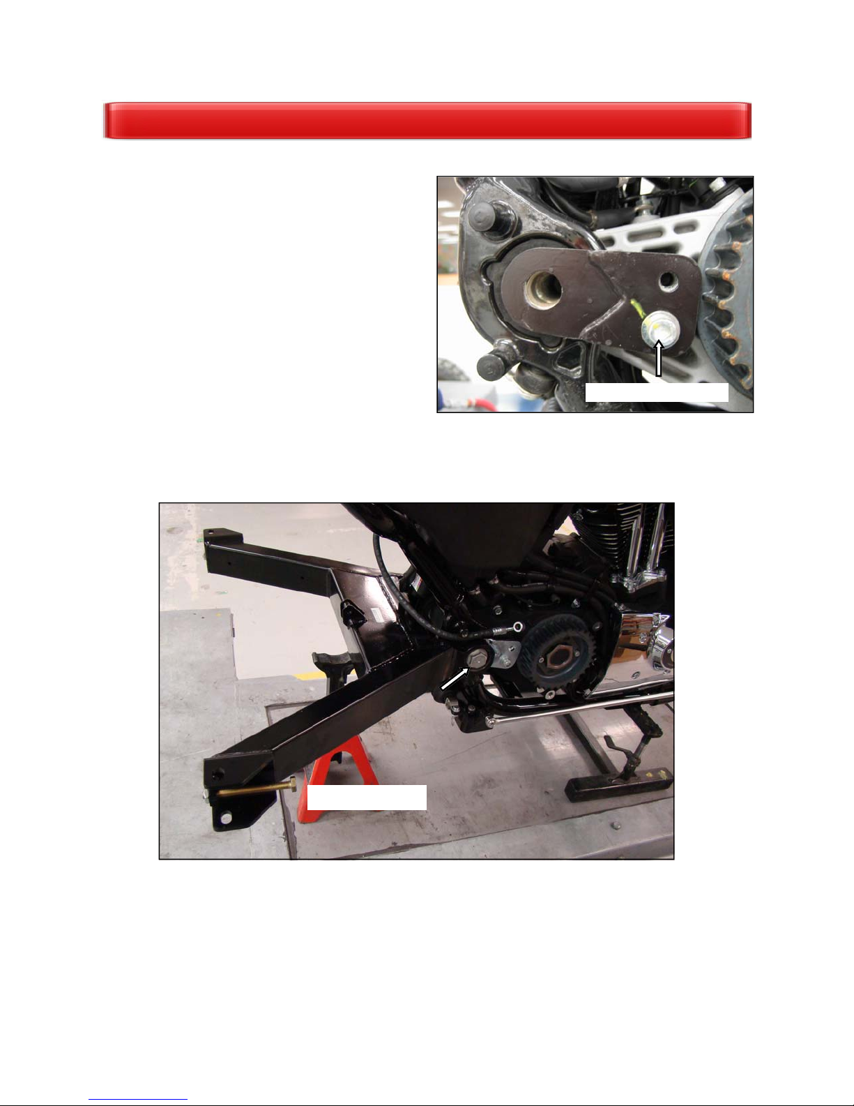
14. See Fig. 1. Remove rear master cylinder and RH
passenger foot peg assembly .
15. Remove rear wheel assembly.
NOTE: OEM swingarm pins will not be reused on
2014+ models.
17. Remove swingarm from H-D frame. Bearings
should be pressed out and reinstalled in trike swin-
garm, Replace bearings if they show signs of wear
or damage.
18. See Fig. 2. Remove rear brake line clamp and
plugs from rear frame.
PREPARING THE MOTORCYCLE
Master cylinder
Remove clamp
Fig. 1
Fig. 2
Remove plugs
RH foot peg

62014+ XL Raider
1. See Fig. 1. Cut crossover pipe even with end
of front head pipe as shown.
2. See Fig. 2. Install steel plug with high temp
silicone into remaining crossover section on
front head pipe. Secure with clamp as shown.
• (1) Steel plug– S002210
• (1) Clamp– S001600
3. See Fig. 3. Cut rear head pipe in front of cross-
over pipe weld as shown. Discard crossover
pipe
EXHAUST MODIFICATION
Fig. 1
Cut crossover pipe here
Front head pipe
Fig. 2
Rear head pipe
Cut rear head pipe here
Fig. 3
Front head pipe
Install plug
and clamp

72014+ XL Raider
1. See Fig. 1. Install master cylinder bracket to
motorcycle frame using the following hardware.
Use Loctite 242 and Torque to 20 ft. lbs. At-
tach OEM brake line and clamp to LH side as
shown.
• (1) Master Cylinder Bracket– S002187
• (2) 5/16” Hex Head Bolt GR8– CB1161
• (2) 5/16” Flat Washers– CW2010
2. See Fig. 2. Install master cylinder to bracket
using the following hardware. Use Loctite 242
and Torque to 35 ft. lbs.
• (1) Master Cylinder– GB6210
• (1) 3/4” Nut– CN3255
3. Screw long end of link rod with 5/16” thin jam
nut into master cylinder. Place 5/16” lock
washer on short end and screw it into HD
pushrod.
• (1) Link Rod– LR6400
• (1) 5/16” Thin Jam Nut– CN3012
• (1) 5/16” Lock Washer– CW2045
4. Extend rod to raise pedal height to top. Lock
jam nuts into place.
5. Test full stroke of master cylinder and check for
binding.
6. See Fig. 3. Attach OEM brake line to master
cylinder using the following hardware. Torque
banjo bolt to 16 ft. lbs.
• (2) Banjo Washers- GC6002
• (1) Banjo Bolt– CB1697
MASTER CYLINDER INSTALLATION
Attach bracket to frame
Fig. 1
Fig. 2
3/4” nut
Link rod
Jam nut
Lock
washer
Install Line
Fig. 3

82014+ XL Raider
7. See Fig. 4. Remove Allen bolt from RH side of
frame below side cover.
8. See Fig. 5 . Install master cylinder reservoir
and mounting bracket to motorcycle frame us-
ing the following hardware. Reuse OEM Allen
bolt to mount bracket to frame.
• (1) Reservoir Bracket- S002191
• (1) Reservoir- S002194
• (2) 1/2” Spacers- S001530
• (1) OEM Allen Head Bolt
• (1) 1/4” x 1-1/4” Button Head Bolt– CB1094
• (1) 1/4” Lock Nut– CN3040
9. See Fig. 5. Attach rubber hose to reservoir as
shown using the following hardware.
• (16.5”) 5/16” Rubber Hose- CH1008
• (1) Hose Clamp– CC2010
10. See Fig. 6. Route brake hose from reservoir
and below swingarm to master cylinder. Install
hose to master cylinder with hose clamp.
• (1) Hose Clamp– CC2010
MASTER CYLINDER INSTALLATION
Fig. 4
Remove OEM bolt
LH side
OEM bolt
Spacers
Fig. 5
Fig. 6
Attach hose
to reservoir
Attach hose to
master cylinder

92014+ XL Raider
1. Press bearing assemblies out of HD swingarm
using an appropriate press collar or socket. Re-
fer to HD service manual for proper procedures.
2. Press bearings into Lehman swingarm. Bearings
should bottom out inside swingarm collar.
NOTE: Make sure there is no dirt or powder coat
material in the bearing bore where the bearing
needs to seat. See Fig. 1.
3. See Fig. 2. Remove top and center bolts from
rear primary cover and drill out to 1/4”.
4. See Fig. 3. Install LH transmission brace behind
primary cover. Install using Loctite 242 with 1/4”
x 2-3/4” bolts and flat washers into top hole and
1/4” x 2-1/2” bolt and flat washer into lower hole.
Both bolts will thread into bracket. Torque to
110 inch lbs.
• (1) LH Transmission Brace– LB6421
• (1) 1/4” x 2-3/4”Socket Bolts- CB1122
• (1) 1/4” x 2-1/2” Socket Bolts CB1116
• (1) 6.4 X 1.6 Flat Washers- CW2160
SWINGARM INSTALLATION
Fig. 3
Fig. 2
Fig. 1
Drill out top 2
holes

10 2014+ XL Raider
5. See Fig. 4. Install RH transmission brace
(LB6404) using Loctite 242 with original bolt in
lower hole only. Leave this bolt loose until
swingarm is in place.
6. Slide swingarm over transmission braces and
line up holes on both sides.
7. Install new swingarm pin through swingarm
from RH side. Apply Loctite 242 to threads and
install OEM nut. Torque to 70 ft. lbs.
• (1) 2014+ Swingarm Pin- S002189
• (1) OEM Pivot Shaft Nut
8. Verify swingarm moves freely up and down.
Place a jack stand under swingarm for support.
Torque RH transmission brace lower bolt to
33 ft. lbs.
SWINGARM INSTALLATION
Fig. 4
Install lower bolt only
Fig. 7
Swingarm installed

11 2014+ XL Raider
1. Remove original upper and lower stabilizer links
from front of motorcycle. Remove lower bracket
at frame. Remove upper bracket at cylinder
head.
2. See Fig. 1. Install two bushings into each side of
new motor mounts. Steel inserts will slide into
bushings.
• (8) Rubber Bushings- LB6402
• (2) Motor Mounts- LL6400
• (4) Steel Inserts– LS1150
3. See Fig. 2. Reinstall original Torx head bolts and
large 3/8” fender washer under upper and lower
RH bolts. Use Loctite 242. Torque to 33 ft. lbs.
• (2) 3/8” Fender Washers– CW2048
4. On lower mount use Loctite 242 on Torx head
bolts to reconnect bracket to frame. Torque to
33 ft. lbs.
5. See Fig. 3. On upper mount use Loctite 242 on
Torx head bolts to frame. Torque to 33 ft. lbs.
Reinstall the engine bracket to cylinder head.
Torque to 60 ft. lbs.
MOTOR MOUNT INSTALLATION
Fig. 1
Fig. 2
Fig. 3
LB6402
Install large
washer to
lower RH bolt
Install large
washer to
upper RH bolt
Upper
Lower
Upper
Lower

12 2014+ XL Raider
1. See Fig. 1. Install adjuster bolts and jam nuts to
each side of swingarm as shown. Bolt head
will face front of bike. Thread bolt into swin-
garm just enough to thread nut on backside.
• (2) Adjuster Bolt M10 X 100 (CB1608)
• (2) Jam Nut M10 (CN1912)
2. Support swingarm with jack stands.
3. See Fig. 2. Attach differential assembly to
swingarm as shown.
• (4) Bolt M12 X 30 (CB1987)
• (4) Nut M12 (CN1917)
NOTE: Swingarm plates will sit above differen-
tial plates Slide differential as far forward as
possible. Set jack stands under axle tubes.
4. Tighten pinch block hardware just enough to
allow differential to slide on swingarm plates.
5. See Fig. 3. Remove upper, lower and rear
housing plates.
6. See Fig. 3. Carefully slide belt over front and
rear pulleys.
7. Reinstall housing plates with original hardware
using Loctite 242. Install all hardware before
tightening. Torque hardware to 17 ft. lbs.
DIFFERENTIAL INSTALLATION
Fig. 2
Fig. 1
Fig. 3
Jam nut
Adjuster
Swingarm plate
on top
Differential
plate
Remove
plates
Install belt

13 2014+ XL Raider
NOTE: Once proper belt tracking is achieved the
shocks will need to be removed.
1. Temporarily install shocks to trike as shown.
2. See Fig. 1. Install spacer between shock and
frame on upper RH side. Use 1/2” x 2-3/4” bolt
and 14mm flat washer.
• (1) RH Shock Spacer– S001941
• (1) 1/2” x 2-3/4” Hex Bolt– CB1427
• (1) 14mm Flat Washer– CW2155
3. See Fig. 2. RH Shock will mount to threaded
hole on RH axle tube with shoulder bolt and flat
washer.
• (1) 1/2” X 1-1/2” Shoulder Bolt– CB1426
• (1) 14mm Flat Washer– CW2155
4. See Fig. 3. Install LH shock as shown using
original H-D hardware.
DIFFERENTIAL INSTALLATION
Fig. 2
Fig. 8
Fig. 1
Spacer
Thread bolt
into axle tube
RH Shock
RH Shock
LH Shock
CB1426
1/2” Shoulder
3/8” Threads

14 2014+ XL Raider
1. Using adjuster bolts, push differential assembly
back until belt has about 3/8” slack with 10 lbs.
pressure at midpoint of bottom run. Measure
between swingarm and differential to ensure
that both sides are equal distance.
2. Rotate pulleys forward for at least 3 revolutions
of rear pulley by pulling backwards on bottom
run of belt. Pull belt straight back to get an ac-
curate reading. Check that belt is not climbing
flanges on rear pulley. The adjusters may need
to be moved in or out from side to side to
achieve proper tracking.
3. Torque rear differential plate bolts to 75 ft. lbs.
4. See Fig. 1. Once proper tracking is obtained,
re-check belt tension. The correct deflection
is 5/16” – 3/8” with 10 lbs. of pressure ap-
plied.
5. Torque and mark (4) “Swingarm to Differential
Bolts” to 93 ft. lbs. using 16mm shallow socket
and 18mm wrench.
6. Adjust belt tension by loosening rear plate bolts
and moving adjusters same amount on both
sides. If any adjustment is made you must re-
check belt tracking.
NOTE: Be sure belt is not climbing up side of
the pulley or squeaking as belt is rotated.
8. After all adjustments are made, tighten adjuster
lock nuts.
9. Remove rear shocks for body installation.
NOTE: Body will interfere with shocks during
installation if they are not removed.
10. See Fig. 2. Chrome sprocket cover will need to
be modified before reinstalling. Trim 3/16” from
inner shaft to allow clearance with new trans-
mission bracket in place.
11. Reinstall cover using two 1/4” washers behind
the lower mounting hole to achieve proper
clearance with front pulley. Chrome exhaust
bracket will also be reinstalled Use original
mounting hardware.
• (2) 1/4” Flat Washer– CW2005
NOTE: Torque 1/4” bolt to 110 in. lbs. Torque
3/8” bolt to 33 ft. lbs.
BELT TENSIONING
Fig. 1
Drive belt deflection
Fig. 2
Trim 3/16”

15 2014+ XL Raider
1. See Fig’s 1 thru 3. Install differential brace to
trike as shown adjusting as necessary for fit-
ment. Attach to housing and swingarm using the
following hardware.
• (1) M10 X 35 Bolt- CB1607
• (1) M8 X 40 Bolt- CB1975
• (1) Conical Spacer- S001784
• (1) M10 Lock Nut- CN3049
2. Tighten jam nuts on differential brace after final
adjustments are made.
3. Torque front differential housing brace bolt to
17 ft. lbs.
4. Torque differential brace bolt (swingarm side) to
36 ft. lbs.
STABILIZER INSTALLATION
Fig. 1
Fig. 2
Install spacer
in housing
Fig. 3

16 2014+ XL Raider
1. See Fig. 1. Attach brass block to swingarm
using the following hardware. Insert spacer
under brass block.
• (1) Brass Block– S002123
• (1) 1/4” x 3/4” Bolt– CB1100
• (1) 1/4” Flat Washer- CW2005
• (1) Spacer– S001530
2. Attach brake lines and residual valve to brass
tee. Torque valve to 11 ft-lbs.
• (2) Brake Lines– S001976
• (1) Residual Valve- S002037
• (1) Banjo Washer– GC6002
3. See Fig. 2. Route OEM line above swingarm
to residual valve as shown. Secure brake line
to swingarm with cable tie.
4. See Fig. 2. Install OEM Brake line to residual
valve using the following hardware. Torque
banjo bolt to 16 ft-lbs.
• (1) M10 Banjo Bolt– CB6001
• (2) Banjo Washers– GC6002
BRAKE INSTALLATION
Fig. 2
Fig. 1

17 2014+ XL Raider
5. See Figs. 3 & 4. Install brake lines to calipers
with the following hardware. Torque banjo
bolts to 16 ft. lbs.
• (1) M10 Banjo Bolt– CB6001
• (2) Banjo Washer– GC6002
6. See Figs. 3 & 4. Secure brake lines to swin-
garm with brake line routing clips in swingarm.
Secure to differential with cable tie as shown.
• (4) Brake Line Clip- S001650
• (2) Cable Tie– CT1036
WARNING: Use correct DOT-rated brake fluid
7. Fill brake system with fluid. Bleed rear brake
system with bleed screws at calipers and check
for leaks.
Fig. 3
BRAKE INSTALLATION
Cable Tie
Clips
Clips
Fig. 4
Cable Tie

18 2014+ XL Raider
Park Brake Assembly
1. See Fig. 1. Install park brake cables to caliper
brackets. Secure cable to bracket with cir-clip
provided on cables.
2. See Fig. 2. Attach park brake bracket with RH
body mount bracket to trike using original foot
peg mounting holes using the following hard-
ware. Body mount will go on outside of park
brake bracket. Spacers will go over bolts on
inside of bracket. Torque to 33 ft. lbs.
• (1) Park Brake Bracket– LB6412
• (1) RH Body Mount– LB6408
• (2) Short Spacers– LS6404
• (2) 3/8” x 2” Bolt– CB1255
• (2) 3/8” Flat Washers– CW2015
3. See Fig. 3. LH body mount will use longer
spacers with the following hardware. Brake
line clamp will be installed on lower bolt.
• (1) LH Body Mount– LB6407
• (2) Long Spacers– LS6405
• (2) 3/8” x 2” Bolt– CB1255
• (2) 3/8” Flat Washers– CW2015
• (1) Brake Line Clamp– GC0112
PARK BRAKE INSTALLATION
Brake line clamp
RH body mount bracket
Park brake bracket
Short spacers
LH body mount bracket
Fig. 3
Fig. 2
Fig. 1

19 2014+ XL Raider
4. See Fig. 4. Remove snap ring from one side of
pin on park brake lever. Hold handle on its side
and push release button at end of handle to
allow pin to slide out.
• (1) Park Brake Lever– GB1099M
5. See Fig. 4. Place hand brake within park brake
bracket, ensuring ratchet is secure on cross
brace. Attach with pin and snap ring.
6. See Fig. 4. Attach park brake cable pulling
bracket (LB1294) to hand brake using clevis
pin and cotter key.
7. See Fig. 5. Route long LH park brake cable
above differential and down RH side of hous-
ing. Attach to top of differential housing with
clamp as shown.
• (1) 1/2” Clamp– S001654
• (1) M8 x 30 Button Head Bolt– CB1929
8. See Fig. 5. Route short RH cable under differ-
ential and into park brake bracket. Attach LH
and RH cables together with clamp to lower
axle tube bolt as shown. Check for proper
clearance with other components.
• (1) 3/4” Clamp– GC0108
9. See Fig. 6. Attach park brake cables to bracket
as shown using nuts and washers provided on
cables. Use one nut and washer on each side
of bracket
10. See Fig. 6. Thread one 5/16” NF nut onto each
brake cable. Place threaded end of brake ca-
bles through holes in cable pulling bracket.
Thread a second nut onto each brake cable on
the front of the bracket.
• (4) 5/16” Nuts– CN3009
11. Ensure park brakes are properly set up, adjust
park brake nuts on both sides. Brakes should
hold within 3-4 clicks on lever.
PARK BRAKE INSTALLATION
Attach cables to
park brake bracket
Attach cable ends
to pulling bracket
with jam nuts
Fig. 5
Fig. 6
Attach LH cable
to housing
Secure with
clamp
Fig. 4

20 2014+ XL Raider
1. Reinstall H-D head pipes onto bike.
2. See Fig. 1. Install adapter plate to muffler
bracket using the following hardware. Leave
hardware loose.
• (1) Muffler Bracket– S001903
• (1) Adapter Plate– S002175
• (2) 5/16” x 1” Hex Head GR8 Bolt– CB1161
• (4) 5/16” Flat Washers– CW2010
• (2) 5/16” Lock Nuts– CN3045
3. See Fig. 2. Assemble body/exhaust bracket to
muffler bracket as shown. Insert rubber bush-
ing into muffler bracket first.
• (1) Rubber Bushing- GM0300
• (1) RH Body/Exhaust Bracket- LB6422
• (1) Exhaust Hanger Bracket- S001928
• (2) 5/16” x 1” Hex Head GR8 Bolt– CB1161
• (4) 5/16” Flat Washers– CW2010
• (2) 5/16” Lock Nuts– CN3045
EXHAUST SYSTEM INSTALLATION
Fig. 1
Fig. 2
Install adapter plate
Insert rubber
bushing
Hanger
Body/Exhaust
bracket
Front of bike
Table of contents
Other lehman Trikes Motorcycle manuals