lehman Trikes Renegade User manual

1997-2001 FLH Renegade– Rev. 3
1997-2001
H-D TOURING MODELS
INSTALLATION
INSTRUCTIONS
*1997-01 MODELS REQUIRE BELT UPGRADE
December 2013

1997-2001 FLH Renegade– Rev. 3
Table of Contents
SECTION
Introduction
Unpacking Kit
Preparing Motorcycle
Installing Lehman Swingarm
Top Motor Mount Link
Carrier and Pulleys
Installing Differential
Belt Tensioning and Tracking
Brake Systems
Installing Lehman Frame and Suspension
Installing Exhaust
Lights and Wiring
Body
Neck Race Preload
Motor Mounts
General Information
Replacement Parts
Renegade Torque Specifications
Final Trike Inspection
*Notes before starting conversion
*For 1997-01 models, the standard Lehman Renegade conversion will not accommodate the
original 1-1/2” final drive belt. The following belt replacement is required to properly complete
the Renegade installation.
2
Model Belt Required H-D part number
FLH 1997-01 1-1/8" width, 139 tooth 40024-04

1997-2001 FLH Renegade– Rev. 3
UNDERSTANDING SAFETY LABELS & INSTRUCTIONS
READ AND BECOME FAMILIAR WITH ALL WARNING, CAUTION SYMBOLS AND STATEMENTS
LISTED BELOW AND IN THE TEXT OF THIS MANUAL BEFORE YOU BEGIN WORK.
DANGER, WARNINGS & CAUTION SYMBOLS
Throughout these instructions “Front” or “Forward” refers to the front of the bike. The front of any com-
ponent is the end which faces toward the front of the bike. The “Left” and “Right” hand sides refer to the
position of the parts as viewed by a rider sitting on the seat, facing forward.
NOTE: The symbol HD refers to Harley Davidson. The symbol LH refers to left-hand side while seated
on the bike. The symbol RH refers to the right-hand side while seated on the bike.
These instructions do not include information, specifications, or procedures relating to the motorcycle
itself. For this information, refer to the factory service manual.
The information in these instructions is provided to Lehman Trike dealers. It is proprietary to Lehman
Trikes, Inc. and provided solely for use by dealers. Any unauthorized duplication or distribution is a vio-
lation of international copyright law.
3
This is the safety alert symbol. When you see this
symbol on your machine or in this manual, be alert
to the potential for personal injury. Your safety is
involved!
SAFETY ALERT WARNING indicates a potential hazard
that may result in severe injury or death to the operator, by-
stander or person (s) inspecting or servicing the vehicle.
Indicates a potential hazard that may result in minor per-
sonal injury or damage to the vehicle.
CAUTION indicates special precautions that must be taken
to avoid vehicle damage or property damage.
NOTE provides key information by clarifying instructions.
IMPORTANT provides key reminders during disassembly,
assembly and inspection of components.
WARNING
CAUTION
CAUTION
NOTE:
IMPORTANT:

1997-2001 FLH Renegade– Rev. 3
General Safety Information
This kit is designed to be installed by a competent technician. Improper installation can affect
the safe operation of your trike, which could also result in serious injury or death. Make sure you
have a complete understanding of the work to be preformed. Unqualified installers are urged to
have the unit installed by a trained technician.
• Always protect yourself when the vehicle is in the air. Make sure the vehicle is properly supported
anytime you use a hoist or jack.
• Always use the proper tools.
• Protect your eyes by using proper safety glasses or goggles.
• Read through the installation instructions before you begin. Make sure you have all the proper tools,
parts and skill set to perform the installation safely and completely.
NOTE: Compliance with national (DOT-USA, MOT-Canada), State, Provincial, and local vehicle is
standards is the responsibility of the installer. Installation of the parking brake and grab handles
is necessary to achieve compliance with DOT/MOT.
ARB Label Confirmation– California Kits
1. See Fig. 1. California Air Resource Board (ARB) certification
label must be affixed on all swingarms for kits sold into Califor-
nia.
2. Label should be placed on left side of swingarm 1/2” from rear
weld.
3. Make sure label correlates with correct model year.
4
Fig. 1

1997-2001 FLH Renegade– Rev. 3
Unpacking the Kit The crate contains the following:
• Body
• Differential with brakes
• Tires mounted on rims
• Boxed swingarm
• Lehman frame
• Hardware box containing smaller parts and bolt bags
• Warranty Book
• Owner’s Manual
• Packing/parts list
5
Fig. 1

1997-2001 FLH Renegade– Rev. 3
6
LS2009– 1997-2001 SWINGARM
LF2084-FRAME
MODULAR DIFFERENTIAL

1997-2001 FLH Renegade– Rev. 3
Preparing Motorcycle
The following instructions are a guide to preparing the motorcycle to accept the Lehman Trike Conver-
sion Kit. This will assist you in removing the necessary parts to install the kit.
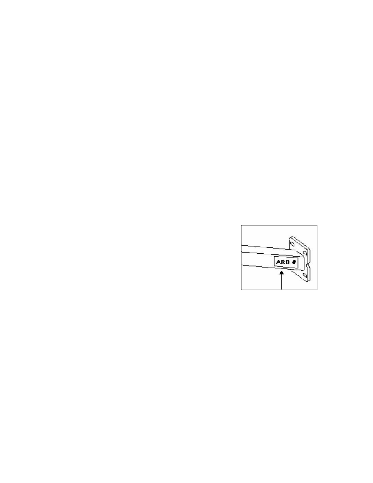
1. Note motorcycle year, model and serial number, as well as Lehman serial number, located
inside body, on left-side of swingarm and on warranty registration form in owner’s manual.
2. Make sure motorcycle is standing straight up and handlebars are centered. Support motorcycle un-
der rear of transmission so it is straight up and down and handlebars are straight. The front forks or
handlebars should be anchored to hold bike.
**NOTE**
Use a small spirit level on rear wheel or disc brake to stand bike straight up. Any movement of
handlebars will move bike off level. Locate reference point on bike frame that is level and check
it frequently.
3. Remove seat and save mounting screw.
4. Disconnect battery.
**CAUTION**
Always disconnect negative battery cable first. If positive cable should contact a grounded ob-
ject while negative cable is installed, resulting sparks may cause an explosion.
5. Remove tour pack. Save mounting bar, spacers and hardware for rear hole.
6. Raise motorcycle lift to working height.
7. Remove side stand mounting bolt and separate side stand from bracket.
8. Remove passenger footboards. Save boards and hardware for re-installation.
9. Remove side covers.
10. Remove rear side cover grommets from motorcycle for use with Lehman side cover mounts.
11. Remove saddlebags (if equipped).
12. Remove mufflers and saddlebag mounts. Keep all muffler mounting hardware including rubber iso-
lators located in saddlebag mounts. These parts will be re-used.
13. Remove rear heat shields from exhaust pipes and loosen head pipe bolts.
14. Remove carriage bolt from lower RH exhaust bracket and save bolt.
15. Support bike on center stand.
16. Disconnect airlines from shocks and remove shocks. Stand shocks upright to prevent oil leaks.
Save air valve plate and discard original shock mounting bolts.
17. Remove rear fender. Save two front mounting bolts. Save turn signal lights and fender mounting
hardware, including stud plate for grab rail. These parts will be re-used.
18. Remove brake line from caliper and remove caliper.
19. Remove clip from rear axle and remove axle nut with 36mm socket. Axle can now be removed.
20. Remove rear wheel assembly.
21. Support transmission from below with jack and padded block.
22. Remove pivot shaft nut from LH side of bike. Remove two swingarm brackets. Tap shaft out of
swingarm and remove from RH side. Swingarm may now be removed.
23. For 1997-2001 models, fuel tank must be removed. Refer to HD service manual for procedure.
7

1997-2001 FLH Renegade– Rev. 3
Installing Lehman Swingarm
Note: If all original components of H-D swingarm are in good working order, they may be re-
used.
1. Press bearing assemblies out of H-D swingarm using appropriate press collar or socket. Refer to
HD service manual.
Note: Make sure there is no dirt or powder coat material in bearing bore where bearing is to be
started.
2. Press bearings into Lehman swingarm following H-D service manual procedure. Bearings should
bottom out on stop in Lehman swingarm collar.
Note: Refer to H-D service manual for swingarm installation procedures and torque specifica-
tions for specific model of motorcycle.
3. Install Lehman swingarm with word “TOP” (stamped into swingarm collar) facing upward. Use Loc-
tite 242 on threads. Torque rear swingarm (fork) pivot shaft to 45 ft.-lbs.
4. Re-install rear swingarm (fork) brackets. Apply Loctite 242 and torque bolts to 42 ft.-lbs.
5. Be sure swingarm moves freely up and down with no side to side movement. Light resistance is
normal.
8

1997-2001 FLH Renegade– Rev. 3
9
Top Motor Mount Link
1. Before loosening lock nuts for original top motor mount
link, measure length from center to center of bolt holes.
2. Remove OEM top motor mount link.
3. Adjust Lehman stabilizer link (Fig. 1) to achieve same
length as OEM motor mount link.
4. See Fig’s. 2 & 3. Position top reinforcement plates
(LB1040) and side plates (LP1200) against frame and out-
line around them.
5. See Fig’s. 2 & 3. Sand or grind frame to bare metal finish
inside outline where brackets will fit. A slightly rough sur-
face is desirable.
Note: Use a generous amount of glue (Loctite 330) to fill between bracket and frame. Apply glue
to plate and spray activator onto glue rather than frame.
Fig. 1
Fig. 2
Fig. 3

1997-2001 FLH Renegade– Rev. 3
6. See Fig. 4. Install 3/8” x 2” bolt, and flat washer through brackets (LB1040) frame shim washers
and lock nut. Use 2-3 “C” clamps to hold bracket to frame. Use 1 “C” clamp to hold side reinforce-
ment plates (LP1200) to frame
7. Allow adhesive to cure for 24 hours.
8. Installation may proceed while glue cures.
9. Attach link assembly to upper frame mounting bracket.
Fig. 4
10

1997-2001 FLH Renegade– Rev. 3
11
10. Link should run horizontal to motorcycle. Be sure to shim both sides of link end with supplied shims
and use OEM spacer (Fig.’s 4 & 5).
11. Tighten all bolts to factory torque specs (frame-22 ft.-lbs., engine-33 ft.-lbs.)
12. Check for any interference of motorcycle parts (wire harnesses, air hoses, etc.).
13. Reroute any wire harnesses around or behind bracket. The coil wire on a fuel-injected model will
run over top edge of bracket.
Note: Make sure harnesses are not pinched when fuel tank is reinstalled.
Fig. 5

1997-2001 FLH Renegade– Rev. 3
12
Head Bolts and Front Motor Mount
FLH Head Bolts
1. Remove existing 3/8” bolt, lock washer and flat washer that holds engine stabilizer bracket to en-
gine.
2. Apply blue Loctite 242 to threads of 3/8” x 1 1/4” hex flange-locking bolt.
3. Assemble bolt, spacer (LS1189) and external tooth lock washer in appropriate order.
4. Torque bolt to 42 ft.-lbs.
5. Reinstall gas tank according to H-D service manual once top motor mount glue is fully cured.
FLH Lower Engine Mount Bolt
1. Remove 3/8” bolt; lock washer and flat washer that holds engine stabilizer to engine.
2. Apply blue Loctite 242 to threads of 3/8” x 1 1/2” hex flange-locking bolt.
3. Install 3/8” x 1 1/2” flanged bolt and original washer. Torque bolt to 42 ft.-lbs.
4. On same bolt, install 3/8” supplied locknut and torque to 38 ft.-lbs.
5. Remove bolt, lock washer and flat washers that hold stabilizer to frame.
6. Apply Loctite to supplied 3/8” x 1 1/2” flanged head bolt. Install supplied bolt with original flat wash-
ers to frame. Torque bolt to 42 ft.-lbs.
7. Remove front engine mount; apply Loctite to threads and re-install nut. Torque bolt to 45-54 ft.-lbs.

1997-2001 FLH Renegade– Rev. 3
13
Differential Installation
1. See Fig. 1. Attach LH adapter plate (LP1038) to
swingarm as shown. Leave hardware loose.
2. See Fig. 2. Attach RH adapter plate to swin-
garm as shown with park brake bracket mounted
to lower holes. Leave hardware loose.
3. See Fig. 1 and 2. Install 3/8” nut to adjuster bolt
and thread into adapter plate from backside. Run
bolt completely into adapter plate.
Fig. 1
Fig. 2

1997-2001 FLH Renegade– Rev. 3
14
4. See Fig. 3 and 4. Loosely install hardware to
pinch blocks before installing differential to
swingarm.
Fig. 3
Fig. 4

1997-2001 FLH Renegade– Rev. 3
15
5. Support swingarm with jack stands.
6. See Fig. 5. With differential assembly on lift,
slide belt over LH axle tube and against center
housing.
7. See Fig. 5. Set differential assembly on swin-
garm adapter plates. Slide differential as far
forward as possible. Set jack stands under
axle tubes.
8. Tighten pinch block hardware just enough to
allow differential to slide on swingarm adapter
plates.
9. See Fig. 5. Remove upper, lower and rear
housing plates.
10. See Fig. 6. Carefully slide belt over pulley.
Reinstall housing plates with original hardware us-
ing Loctite 242. Install all hardware before tighten-
ing. Torque hardware to 17 ft. lbs
Fig. 5
Install belt
Fig. 6
Remove plates

1997-2001 FLH Renegade– Rev. 3
Belt Tensioning and Tracking
1. Center differential to motorcycle frame– this is
critical for proper belt tensioning. Make sure
distance is within 1/16” from side to side.
2. See Fig. 1. Level swingarm to motorcycle frame.
This will help achieve proper ride height. With
standard shocks, measure 12” from inner boss
against center section to center of upper motor-
cycle frame.
3. See Fig. 2. Using adjusters, push differential
assembly back until belt has about 3/8” slack
with 10 lbs. pressure at midpoint of bottom run.
Measure between adapter plates and pinch
blocks to ensure that distances are equal.
4. Rotate pulleys forward for at least 3 revolutions
of rear pulley by pulling backwards on bottom
run of belt. Pull belt straight back to get an accu-
rate reading. Check that belt is running about
0.030” from flange on rear pulley. Tap differen-
tial left or right to achieve this reading. Belt may
ride next to flange as long as it’s not trying to
climb.
5. Tighten socket head screws (8) that hold adapter
plates to swingarm and torque to 35 ft. lbs.
6. Once tracking is obtained, re-check belt tension. Raise and lower differential assembly slowly with a
jack while checking belt tension. When tightest position is located, apply 10 lbs. force at midpoint of
lower strand of belt. Correct deflection is 5/16” - 3/8”.
7. Increase or reduce belt deflection by turning adjuster screw on each side in or out an equal number
of turns.
8. Look along top of belt to check belt alignment on front pulley. There should be about 0.030” clear-
ance between pulley flange and belt. If adjustment is required, loosen cap screws that hold adapter
plate to swingarm and tap differential housing with rubber mallet in desired direction. Check rear
alignment and belt tension again if adjustment is required.
Note: If necessary, apply chalk to edge of belt to aid in getting proper clearance between belt and
pulley flanges. If visible clearance cannot be obtained, be sure belt is not climbing up the side of
pulleys or squeaking as belt is rotated.
9. After all adjustments are made, tighten adjuster lock nuts and tighten pinch block bolts. Tighten
pinch blocks in a crosswise pattern. Go over both sides at least 2 times to seat blocks over pins.
Torque bolts to 25 ft. lbs.
16
Fig. 1
12”
Drive belt deflection
Fig. 2

1997-2001 FLH Renegade– Rev. 3
Disc Brakes
CAUTION: Brakes are a critical safety compo-
nent of the trike. Verify all brake components
have been properly installed before test riding.
Improper brake operation could result in death
or serious injury. Do not allow dirt or debris to
enter master cylinder reservoir. Brake pads will
need to be seated in during initial test ride.
Brake System
1. See Fig. 1. Attach brass tee to differential
brace using the following hardware.
• (1) Brass Tee– CF5105
• (1) Spacer– S001530
• (2) 1/4” x 1-3/4” Hex Bolt– CB1100
• (2) 1/4” Flat Washers– CW2005
• (2) 1/4” Lock Nut– CN3042
2. See Fig. 1. Install original brake line from
master cyclinder and rear braided lines to
brass tee using the following hardware. Torque
banjo bolt to 16 ft. lbs.
• (1) Banjo Bolt– S002022
• (2) Banjo Washers- GC6002
• (2) 45” M10 Braided Line– S001976
3. See Fig. 2. Install (2) braided brake lines to
rear calipers as shown. Torque bolts to 16 ft.
lbs.
• (2) M10 Banjo Bolt– CB6001
• (4) M10 Banjo Washers- GC6002
4. Secure brake lines to swingarm with cable ties.
17
Fig. 1
Fig. 2
OEM line
Spacer
Install brake lines to LH/RH calipers

1997-2001 FLH Renegade– Rev. 3
Note: Be sure you have correct model year res-
ervoir extension pack before proceeding
(Reminder: packs are labeled 1997-2007 and
2008+). 1997-99 models do not require an exten-
sion.
5. See Fig. 3. Remove original master cylinder
reservoir cap screws and discard. Install exten-
sion to master cylinder with new extension
screws. Do not over tighten extension
screws.
Note: Verify all brake lines and hardware are tight
before bleeding system.
6. Add brake fluid (refer to OEM reservoir cap for
brake fluid requirements) to brake system and
work brakes to fill lines.
7. Remove rubber caps on bleeder valves. Install
clear brake bleeder hose over bleeder valve on
caliper.
8. Pump brake pedal to build pressure.
9. While holding the brake pedal, open bleeder
valve to release pressure and remove air from
system. Repeat bleeding on both calipers until
fluid is solid without bubbles in bleeder hose.
10. Tighten bleeder valves and check for leaks.
11. Install master cylinder reservoir cap with new
screws. Do not over tighten cap screws.
Park Brake Assembly
1. See Fig. 4. Install park brake cable to caliper
brackets. Secure cable to bracket with cir-clip
provided on cables.
18
Fig. 3
Supplied screws
Screw extensions
Fig. 4
Attach cable
Secure to bracket

1997-2001 FLH Renegade– Rev. 3
2. See Fig. 5. Remove snap ring from one side of
large clevis pin on brake lever. Hold park brake
lever on its side and push release button at end
of park brake lever to allow clevis pin to slide out.
3. See Fig. 5.Place park brake lever within park
brake bracket, ensuring ratchet is secure on
cross brace. Attach with large clevis pin.
4. See Fig. 5. Attach park brake cable pulling
bracket to brake lever using small clevis pin and
cotter pin.
• (1) Cable Pulling Bracket– LB1294
• (1) Clevis Pin– CC3106
• (1) Cotter Pin- CC4017
5. See Fig. 6. Route left park brake cable above
differential and under motorcycle frame, attach-
ing cable ties to cable and frame, and install in
left hole in handle mount.
6. See Fig. 7. Route right park brake cable up
around axle and forward to right hole in handle
mount.
7. See Fig. 7. Secure both cables to upper rear
pinch block with clamp (GC0108).
8. See Fig. 8. Secure cable retaining nuts to handle
mount with 7/8” wrench.
9. Check for tire clearance.
10. See Fig. 8. Thread one 5/16” NF nut onto each
brake cable. Place threaded end of brake cables
through holes in cable bracket. Thread second
nut onto each brake cable.
11. Adjust park brake cables at handle to engage at
3–4 clicks.
Note: Take up slack in cables before tightening
ends to ensure good adjustment range with
threaded end of brake cables.
19
Fig. 6
Left park brake cable
Fig. 7
Fig. 8
Cable routing
Cable retaining nuts
Adjuster nuts
Attach clamp
Fig. 5

1997-2001 FLH Renegade– Rev. 3
20
Installing Lehman Frame and
1. See Figs. 1-3. Install frame plates to H-D frame with (2)
5/16” X 1 1/2” bolts, flat washers (if necessary, between
frame plate and motorcycle frame) and lock nuts for
front hole only. Rear bolt will be used with imitation
fender. Do not tighten bolts.
Note: See Fig. 1. Front bolt on each side will install
from inside with head of bolt toward middle of trike.
This provides clearance between fender and bolt.
2. Set frame in place and install (2) 1/2” X 1 1/2” bolts, flat
washers and lock washers, through front holes of trike
frame and into original shock mount on H-D frame.
3. See Fig. 2 and 3. Attach frame plates (LB1220) to Leh-
man frame plate using 5/16” X 1” bolts, flat washers and a
lock nuts.
4. See Fig. 2. Level Lehman frame to H-D frame. Frames
should be parallel with each other. Tighten all bolts when
level. Torque front 1/2” bolts to 78 ft.-lbs. Torque all
frame plate bolts to 19 ft. lbs.
5. See Fig. 3. Lower differential and install 1/2” X 2 1/4”
bottom shock bolt through lower shock eye and thread it
into shock plate. Use (1) washer under head of bolt.
Torque bolt to 40 ft.-lbs. and secure bolt with lock nut.
Note: Do not install flat washer under lock nut.
6. See Fig. 3. Raise differential and install top of shock using 1/2” X 2 1/4” bolt, lock washers and (1)
washer under head of bolt. Shock should run parallel to frame tube when viewed from rear. Torque
shock bolts to 40 ft.-lbs.
Fig. 2
Fig. 1
Front bolt on each side
Rear bolt on each side
Fig. 3
Level frame Frame plate
Table of contents
Other lehman Trikes Motorcycle manuals