LEI accessories PD-N User manual

PT-W
PT-W, PD-W, PD-WBK,
PD-N and PD-NBK
TRANSDUCERS
INSTALLATION MANUAL
PD-N and
PD-WBK
PD-W and
PD-WBK

When the transducer is mounted on the outside of the hull, periodi-
cally wash the transducer’s face with soap and water to remove any
oil film that may collect. Oil and dirt on the face will reduce the
sensitivity or may even prevent operation.
NOTICE
CopyrightCopyright
CopyrightCopyright
Copyright ©©
©©
©1995, 1996 Lowrance Electronics, Inc.1995, 1996 Lowrance Electronics, Inc.
1995, 1996 Lowrance Electronics, Inc.1995, 1996 Lowrance Electronics, Inc.
1995, 1996 Lowrance Electronics, Inc.
All rights reserved.All rights reserved.
All rights reserved.

1
PT-W INSTALLATION INSTRUCTIONS ONLY
GOOD
MOUNTING
LOCATIONS
The PT-W is a wide cone angle (20 degree) transducer designed to be
used with portable sonar units.
Assemble the transducer and bracket as shown below. Press the
rubber grommet into the hole in the top of the bracket. Tie one end of
the lanyard through this hole.
To use the PT-W, choose an area on the transom that is free from air
bubbles when the boat is moving. Although this is not a high speed
transducer, it will operate when the boat is moving faster than trolling
speeds. It is important to mount the transducer in an area that is free
from air bubbles, since they cause interference on the sonar's display.
Once a good location is found, clean the area before attaching the
suction cup. Moisen the suction cup and press it firmly onto the hull.
The suction cup should be mounted just above the bottom edge of the
hull. This allows the transducer a good chance to be in smooth water at
all times.
Tie the lanyard to the boat. This will prevent the loss of the transducer if
the suction cup comes loose. Route the transducer cable to the sonar
unit.

2
Location - General
1. The transducer must be placed in a location that has a smooth flow of
water at all times. If the transducer is to be mounted inside the hull,
then the chosen location must be in the water at all times. If the
transducer is not placed in a smooth flow of water, interference will
show on the sonar’s display in the form of random lines or dots
whenever the boat is moving.
2. The transducer should be installed with it’s face pointing straight
down, if possible.
3. If possible, route the transducer cable away from other wiring on the
boat. Electrical noise from engine wiring can be displayed on the
sonar’s screen. Noise from bilge pumps and aerators can also be
picked up, so use caution when routing the transducer cable around
these wires, also.
PD-WPD-W
PD-WPD-W
PD-W
PD-WBKPD-WBK
PD-WBKPD-WBK
PD-WBK
PD-NPD-N
PD-NPD-N
PD-N
PD-NBKPD-NBK
PD-NBKPD-NBK
PD-NBK
The PD-W and PD-WBK are wide
cone angle (20 degree) transducers
and can be mounted to shoot
through the hull, or, with an automo-
tive hose clamp, attached to a troll-
ing motor. The PD-N and PD-NBK
narrow cone angle (8 degree) trans-
ducers are shoot-thru-hull mount
only.
Read this manual carefully before
attempting the installation. Use ex-
treme care if mounting the trans-
ducer inside the hull, since once it is
epoxied into position, the trans-
ducer usually cannot be removed.
Remember, the transducer location
is the most critical part of a sonar
installation. If it isn’t done properly,
the sonar can’t perform at it’s de-
signed potential.
PD-W & PD-N INSTALLATION INSTRUCTIONS

3
SHOOT-THRU-HULL
The transducer installation inside a fiberglass hull must be in an area
that does not have air bubbles in the resin or separated fiberglass
layers. The sonar signal must pass through solid fiberglass. A success-
ful transducer installation can be made on hulls with flotation materials
(such as plywood, balsa wood, or foam) between layers of fiberglass if
the material is removed from the chosen area. For example, some
manufacturers use a layer of fiberglass, then a core of balsa wood,
finishing with an outer layer of fiberglass. Removing the inner layer of
fiberglass and the balsa wood core exposes the outer layer of fiberglass.
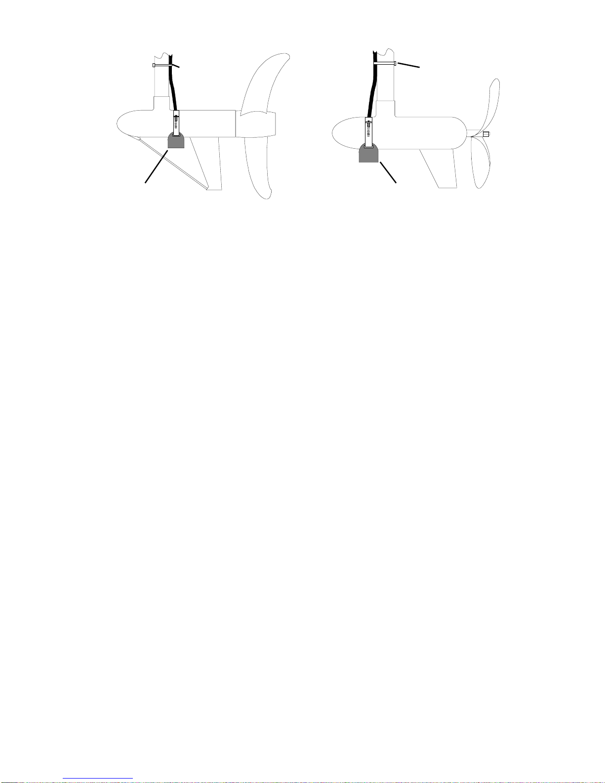
The transducer can then be epoxied directly to the outer layer of fiber-
glass. Epoxy is poured into the hole and the transducer is then placed
into the epoxy. After the epoxy cures, the hull is watertight and structur-
ally sound. Remember, the sonar signal must pass through solid fiber-
glass. Any air bubbles in the fiberglass or the epoxy will reduce or
eliminate the sonar signals.
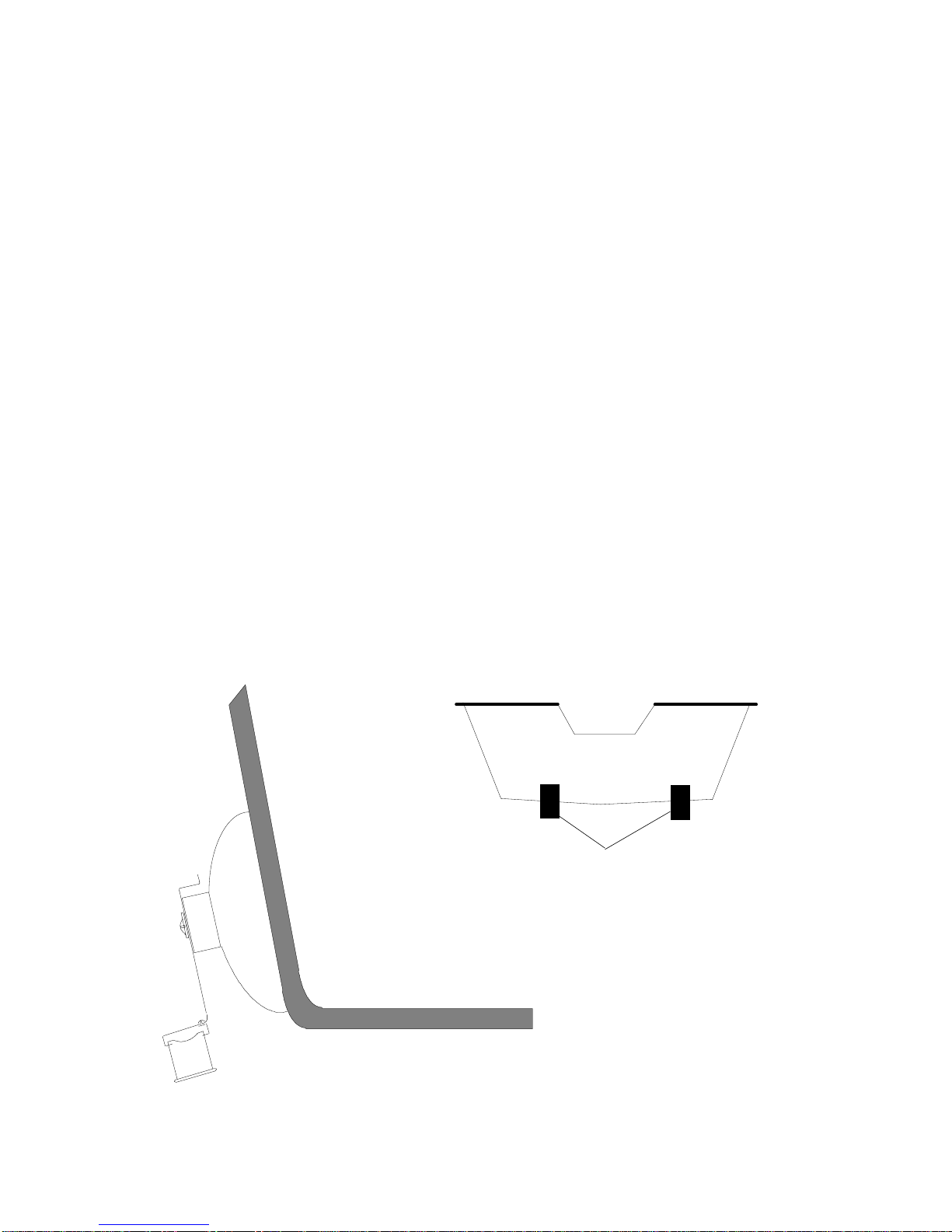
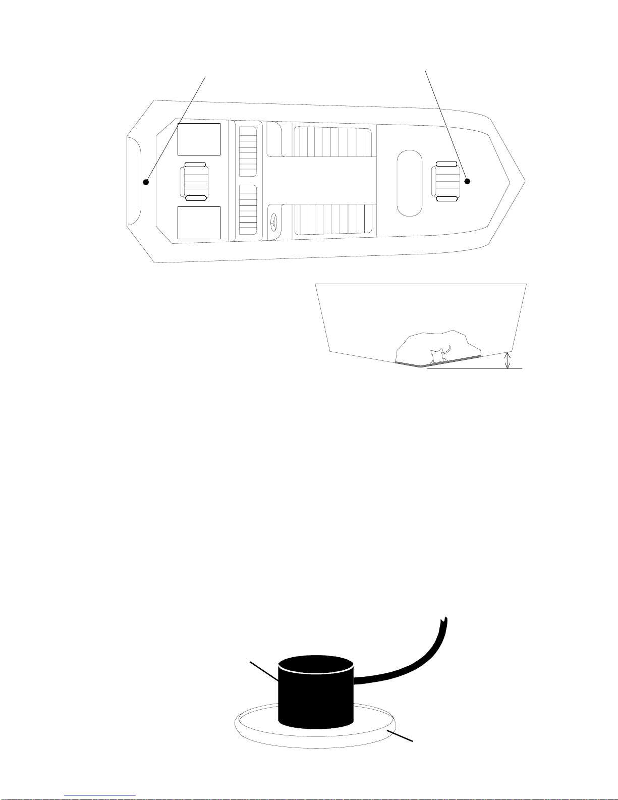
To choose the proper location for thru-hull mounting, anchor the boat in
60 feet of water. Add a little water to the sump of the boat. Plug the
transducer into the sonar unit, turn it on, then hold the transducer over
the side of the boat. Adjust the sensitivity and range controls until a
second bottom echo is seen on the display. (you will need to turn the
automatic and ASP functions off on L.C.G. units.) Don’t touch the
controls once they’ve been set. Next, take the transducer out of the
water and place it in the water in the sump of the boat. Observe the
sonar signal to see if there is a noticeable decrease in sensitivity. The
second bottom signal may disappear and the bottom signal may de-
crease in intensity. Move the transducer around to find the best location.
If the sensitivity control has to be increased greatly to compensate, then
a different type of transducer should be mounted on the outside of the
hull. If not, then mark the location that shot through the hull the best and
follow the instructions below for a thru-hull mounting.

4
(HIGH SPEED)(HIGH SPEED)
(HIGH SPEED) TRANSDUCER LOCATIONTRANSDUCER LOCATION
TRANSDUCER LOCATIONTRANSDUCER LOCATION
TRANSDUCER LOCATION
(TROLLING SPEEDS)(TROLLING SPEEDS)
(TROLLING SPEEDS)
TRANSDUCER LOCATIONTRANSDUCER LOCATION
TRANSDUCER LOCATION
Shoot-thru-hull Installation
1. Dry the chosen area thoroughly, then sand both the inside surface of
the hull and the face of the transducer with 100 grit sandpaper. The
surface of the hull must be flat so the entire transducer face is in
contact with the hull prior to bonding.
2. Make certain the area is clean, dry, and free of oil or grease. Build a
small dam out of caulking compound or RTV around the mounting
area. It should be at least 1/2" greater in diameter than the trans-
ducer. Use a good two-part epoxy that sets up rock hard. Do not use
5 minute or “fast setting” epoxy. Do not use RTV silicone rubber
adhesive or any other glue.
TRANSDUCERTRANSDUCER
TRANSDUCER
RTV DAMRTV DAM
RTV DAMRTV DAM
RTV DAM
DEADRISE LESS THAN TENDEADRISE LESS THAN TEN
DEADRISE LESS THAN TEN
DEGREESDEGREES
DEGREESDEGREES
DEGREES

5
HULLHULL
HULLHULL
HULL RTV DAMRTV DAM
RTV DAMRTV DAM
RTV DAM
EPOXYEPOXY
EPOXYEPOXY
EPOXY
3. Follow the instructions on the epoxy package and mix it thoroughly.
Do not mix it too fast, as it will cause bubbles to form in the epoxy.
Apply a small amount on the entire face of the transducer, then pour
1/16" level into the area contained by the dam. Place the transducer
into the epoxy, twisting and turning it to force any air bubbles out from
under the transducer face. The face of the transducer should be
parallel with the hull, with a minimum amount of epoxy between the
hull and transducer. Hold the transducer down with a weight until the
epoxy dries. Afterwards, route the cable to the sonar unit.

6
LITHO IN U.S.A. 988-0140-30
CABLE TIECABLE TIE
CABLE TIECABLE TIE
CABLE TIE
TRANSDUCERTRANSDUCER
TRANSDUCER
CABLE TIECABLE TIE
CABLE TIECABLE TIE
CABLE TIE
TRANSDUCERTRANSDUCER
TRANSDUCER
Trolling Motor Mount - PD-W Only
The top of the transducer is curved to fit the contour of the motor on
electric trolling motors. Attach it using a automotive hose clamp avail-
able at any auto parts store.
1. Measure the diameter of your trolling motor and purchase a hose
clamp slight larger.
2. Determine the mounting location. It should be ahead of the skeg.
Water turbulence is at a minimum at this position. Some trolling
motors have a wire brace from the motor to the skeg. The transducer
won’t be affected by this.
3. Position the transducer to aim straight down with the cable angled
away form the direction of travel. Mount it with the hose clamp.
4. Tie the cable to the motor shaft using plastic cable ties (available at
automotive or electrical supply stores). Be certain there is enough
slack for the motor to turn freely.
This manual suits for next models
14
Table of contents
Other LEI accessories Transducer manuals
Popular Transducer manuals by other brands

SOLIDDRIVE
SOLIDDRIVE MSK-1 Installation and use guide

Matelec
Matelec FPC-12569 quick start guide

Pulsar Measurement
Pulsar Measurement HART dBi Series installation manual

S+S Regeltechnik
S+S Regeltechnik PREMASGARD 111x manual

S+S Regeltechnik
S+S Regeltechnik THERMASGARD MWTM Series Operating Instructions, Mounting & Installation

Aplisens
Aplisens PM-22 user manual