Leica Geosystems iCON gps 60 User manual

Leica iCON gps 60
User Manual
Version 2.7
English

iCON gps 60, Introduction 2
Introduction
Purchase Congratulations on the purchase of a Leica iCON gps 60 system.
This manual contains important safety directions as well as instructions for setting up
the product and operating it. Refer to "1 Safety Directions" for further information.
Read carefully through the User Manual before you switch on the product.
Product Identifica-
tion
The model and serial number of your product are indicated on the type plate.
Always refer to this information when you need to contact your agency or Leica
Geosystems authorised service centre.
Trademarks • Windows is a registered trademark of Microsoft Corporation in the United States
and other countries
• CompactFlash and CF are trademarks of SanDisk Corporation
• Bluetooth®is a registered trademark of Bluetooth SIG, Inc.
All other trademarks are the property of their respective owners.
Validity of this
manual
This manual applies to the Leica iCON gps 60 SmartAntenna.
Available documen-
tation
Refer to the following resources for all Leica iCON gps 60 documentation/soft-
ware:
• the Leica USB documentation card
• https://myworld.leica-geosystems.com
myWorld@Leica Geosystems (https://myworld.leica-geosystems.com) offers a
wide range of services, information and training material.
With direct access to myWorld, you are able to access all relevant services whenever
it is convenient for you, 24 hours a day, 7 days per week. This increases your efficiency
and keeps you and your equipment instantly updated with the latest information from
Leica Geosystems.
Name Description/Format
Leica iCON gps
60 Quick Guide
Provides an overview of the product together with tech-
nical data and safety directions. Intended as a quick
reference field guide.
Leica iCON gps
60 User Manual
All instructions required in order to operate the product
to a basic level are contained in the User Manual.
Provides an overview of the product together with tech-
nical data and safety directions.
Service Description
myProducts Add all products that you and your company own and explore your
world of Leica Geosystems: View detailed information on your prod-
ucts and update your products with the latest software and keep up-
to-date with the latest documentation.
myService View the current service status and full service history of your prod-
ucts in Leica Geosystems service centres. Access detailed informa-
tion on the services performed and download your latest calibration
certificates and service reports.

iCON gps 60, Introduction 3
mySupport View the current service status and full service history of your prod-
ucts in Leica Geosystems service centres. Access detailed informa-
tion on the services performed and download your latest calibration
certificates and service reports.
myTraining Enhance your product knowledge with Leica Geosystems Campus -
Information, Knowledge, Training. Study the latest online training
material on your products and register for seminars or courses in
your country.
myTrustedSer-
vices
Add your subscriptions and manage users for Leica Geosystems
Trusted Services, the secure software services, that assist you to
optimise your workflow and increase your efficiency.
Service Description

iCON gps 60, Table of Contents 4
Table of Contents
In this manual Chapter Page
1 Safety Directions 7
1.1 General Introduction 7
1.2 Definition of Use 7
1.3 Limits of Use 8
1.4 Responsibilities 8
1.5 Hazards of Use 8
1.6 Electromagnetic Compatibility EMC 11
1.7 FCC Statement, Applicable in U.S. 13
1.8 IC Statement, Applicable in Canada 14
2 Description of the System 15
2.1 System Components 15
2.2 Unpacking the Container 17
2.2.1 Base Station Container 17
2.2.2 Rover Setup Container 19
2.3 Instrument Components 20
2.4 Compatible Field Controllers 20
2.4.1 Available Field Controller 20
2.4.2 Holder and Clamps for Field Controllers 22
2.4.3 iCON Series Field Software Overview 23
3 Using the iCON gps 60 SmartAntenna 24
3.1 Power Supply 24
3.2 Batteries 24
3.2.1 Installing the Internal Battery 24
3.2.2 General Battery Handling 25
3.3 Installing a SIM Card 25
3.4 Slot-in-Device 26
3.5 External Radios 26
3.6 Using USB Memory Devices 27
3.7 Installing Adapters 27
3.8 Installation on a Machine 28
3.9 Antenna Heights 29
3.9.1 Understanding Antenna Heights 29
3.9.2 The Mechanical Reference Plane, MRP 29
3.9.3 Measuring the Antenna Height for a Pillar Setup 30
3.9.4 Measuring the Antenna Height for a Tripod Setup 32
3.9.5 Measuring the Antenna Height for a Pole Setup 33
4 Setups with Accessories 34
4.1 Real-Time Base Setup 34
4.2 Local Base Station Setup with External GNSS Antenna 35
4.3 Real-Time Base with Raw Data Logging 36
4.4 Raw Data Logging Setup 38
4.5 Real-Time Rover Setup 38
4.6 Setup for Machine Use 40
4.7 Establish Bluetooth Data Connection 40
5 iCON gps 60 SmartAntenna User Interface 41
5.1 User Interface Description 41
5.2 Main Menu 42

iCON gps 60, Table of Contents 5
5.3 Submenus 45
5.3.1 Navigation in Submenus 45
5.3.2 How to Change Settings and Edit Values 45
5.3.3 Available Sub Menus 47
6 Software Tools 55
6.1 Base Setup 55
6.1.1 Base Setup Description 55
6.1.2 Manual Base Setup 55
6.1.3 Base Setup using BasePilot 67
6.2 Rover Setup 68
6.3 ORP and NMEA Output 73
6.4 Raw Data Logging 75
6.5 iCON Telematics 75
6.6 Import, Export, or Delete Data 78
6.7 Licensing 80
7 Coordinate Systems 81
8 Care and Transport 82
8.1 Transport 82
8.2 Storage 82
8.3 Cleaning and Drying 82
9 Technical Data 84
9.1 Technical Data iCON gps 60 SmartAntenna 84
9.1.1 Tracking Characteristics 84
9.1.2 Accuracy 84
9.1.3 General Technical Data of the Instrument 85
9.2 Antennas Technical Data 88
9.3 Pin Assignments and Sockets 89
9.4 Conformity Declarations 90
9.4.1 iCON gps 60 90
9.4.2 GFU14, SATEL Satelline 3AS, GFU27, SATEL Satelline
M3-TR1 93
9.4.3 GFU15, Pacific Crest PDL 94
9.4.4 TFR-300L 95
9.4.5 CCD7 - SATEL TA13 95
9.4.6 CCD8 - Intuicom 900SLR 96
10 Software Licence Agreement 98
Appendix A NMEA Message Formats 99
A.1 Overview 99
A.2 Symbols Used for Describing the NMEA Formats 99
A.3 GGA - Global Positioning System Fix Data 101
A.4 GGK - Real-Time Position with DOP 102
A.5 GGQ - Real-Time Position with CQ 103
A.6 GLL - Geographic Position Latitude/Longitude 104
A.7 GNS - GNSS Fix Data 104
A.8 GSA - GNSS DOP and Active Satellites 105
A.9 GSV - GNSS Satellites in View 106
A.10 HDT - Heading, True 107
A.11 LLK - Leica Local Position and GDOP 107
A.12 LLQ - Leica Local Position and Quality 108
A.13 RMC - Recommended Minimum Specific GNSS Data 109

iCON gps 60, Table of Contents 6
A.14 VTG - Course Over Ground and Ground Speed 109
A.15 ZDA - Time and Date 110
Appendix B ORP – Orientation and Position 111
Appendix C Glossary 114
C.1 C 114
C.2 G 115
C.3 N 116
C.4 W 117

iCON gps 60, Safety Directions 7
1 Safety Directions
1.1 General Introduction
Description The following directions enable the person responsible for the product, and the
person who actually uses the equipment, to anticipate and avoid operational hazards.
The person responsible for the product must ensure that all users understand these
directions and adhere to them.
About Warning
Messages
Warning messages are an essential part of the safety concept of the instrument. They
appear wherever hazards or hazardous situations can occur.
Warning messages...
• make the user alert about direct and indirect hazards concerning the use of the
product.
• contain general rules of behaviour.
For the users‘ safety, all safety instructions and safety messages shall be strictly
observed and followed! Therefore, the manual must always be available to all persons
performing any tasks described here.
DANGER, WARNING, CAUTION and NOTICE are standardised signal words for iden-
tifying levels of hazards and risks related to personal injury and property damage. For
your safety, it is important to read and fully understand the following table with the
different signal words and their definitions! Supplementary safety information
symbols may be placed within a warning message as well as supplementary text.
Type Description
DANGER Indicates an imminently hazardous situation which, if not
avoided, will result in death or serious injury.
WARNING Indicates a potentially hazardous situation or an unintended
use which, if not avoided, could result in death or serious injury.
CAUTION Indicates a potentially hazardous situation or an unintended
use which, if not avoided, may result in minor or moderate
injury.
NOTICE Indicates a potentially hazardous situation or an unintended
use which, if not avoided, may result in appreciable material,
financial and environmental damage.
Important paragraphs which must be adhered to in practice as
they enable the product to be used in a technically correct and
efficient manner.

iCON gps 60, Safety Directions 8
1.2 Definition of Use
Intended use • Computing with software.
• Carrying out measurement tasks using various GNSS measuring techniques.
• Recording GNSS and point related data.
• Remote control of product.
• Data communication with external appliances.
• Measuring raw data and computing coordinates using carrier phase and code signal
from GNSS satellites.
Reasonably fore-
seeable misuse
• Use of the product without instruction.
• Use outside of the intended use and limits.
• Disabling safety systems.
• Removal of hazard notices.
• Opening the product using tools, for example screwdriver, unless this is permitted
for certain functions.
• Modification or conversion of the product.
• Use after misappropriation.
• Use of products with obvious damages or defects.
• Use with accessories from other manufacturers without the prior explicit approval
of Leica Geosystems.
• Inadequate safeguards at the working site.
• Controlling of machines, moving objects or similar monitoring application without
additional control and safety installations.
1.3 Limits of Use
Environment Suitable for use in an atmosphere appropriate for permanent human habitation: not
suitable for use in aggressive or explosive environments.
DANGER Local safety authorities and safety experts must be contacted before working in
hazardous areas, or close to electrical installations or similar situations by the person
in charge of the product.
1.4 Responsibilities
Manufacturer of
the product
Leica Geosystems AG, CH-9435 Heerbrugg, hereinafter referred to as Leica Geosys-
tems, is responsible for supplying the product, including the user manual and original
accessories, in a safe condition.

iCON gps 60, Safety Directions 9
Person responsible
for the product
The person responsible for the product has the following duties:
• To understand the safety instructions on the product and the instructions in the
user manual.
• To ensure that it is used in accordance with the instructions.
• To be familiar with local regulations relating to safety and accident prevention.
• To inform Leica Geosystems immediately if the product and the application
becomes unsafe.
• To ensure that the national laws, regulations and conditions for the operation of
e.g. radio transmitters or lasers are respected.
• To ensure that the radio modem is not operated without the permission of the local
authorities on frequencies and/or output power levels other than those specifically
reserved and intended for use without a specific permit.
The internal and external radio modems have been designed to operate on
frequency ranges and output power ranges, the exact use of which differs from one
region and/or country to another.
1.5 Hazards of Use
CAUTION Watch out for erroneous measurement results if the product has been dropped or has
been misused, modified, stored for long periods or transported.
Precautions:
Periodically carry out test measurements and perform the field adjustments indicated
in the user manual, particularly after the product has been subjected to abnormal use
as well as before and after important measurements.
DANGER Because of the risk of electrocution, it is dangerous to use poles and extensions in the
vicinity of electrical installations such as power cables or electrical railways.
Precautions:
Keep at a safe distance from electrical installations. If it is essential to work in this
environment, first contact the safety authorities responsible for the electrical instal-
lations and follow their instructions.
WARNING During dynamic applications, for example stakeout procedures there is a danger of
accidents occurring if the user does not pay attention to the environmental conditions
around, for example obstacles, excavations or traffic.
Precautions:
The person responsible for the product must make all users fully aware of the existing
dangers.
WARNING Inadequate securing of the working site can lead to dangerous situations, for example
in traffic, on building sites and at industrial installations.
Precautions:
Always ensure that the working site is adequately secured. Adhere to the regulations
governing safety, accident prevention and road traffic.

iCON gps 60, Safety Directions 10
CAUTION If the accessories used with the product are not properly secured and the product is
subjected to mechanical shock, for example blows or falling, the product may be
damaged or people can sustain injury.
Precautions:
When setting up the product, make sure that the accessories are correctly adapted,
fitted, secured, and locked in position.
Avoid subjecting the product to mechanical stress.
WARNING If the product is used with accessories, for example masts, staffs, poles, you may
increase the risk of being struck by lightning.
Precautions:
Do not use the product in a thunderstorm.
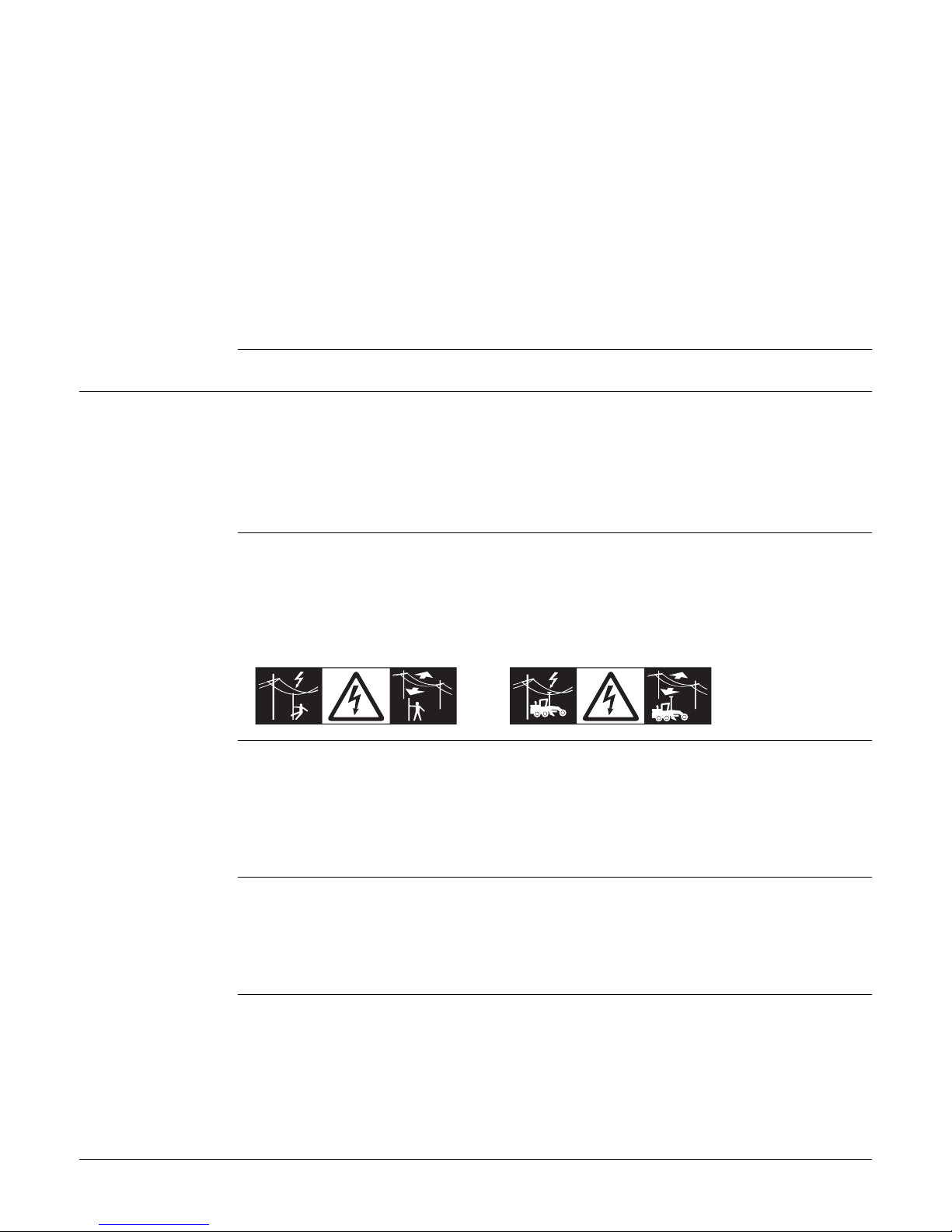
DANGER If the product is used with accessories, for example on masts, staffs, poles, you may
increase the risk of being struck by lightning. Danger from high voltages also exists
near power lines. Lightning, voltage peaks, or the touching of power lines can cause
damage, injury and death.
Precautions:
• Do not use the product in a thunderstorm as you can increase the risk of being
struck by lightning.
• Be sure to remain at a safe distance from electrical installations. Do not use the
product directly under or close to power lines. If it is essential to work in such an
environment contact the safety authorities responsible for electrical installations
and follow their instructions.
• If the product has to be permanently mounted in an exposed location, it is advis-
able to provide a lightning conductor system. A suggestion on how to design a
lightning conductor for the product is given below. Always follow the regulations in
force in your country regarding grounding antennas and masts. These installations
must be carried out by an authorised specialist.
• To prevent damages due to indirect lightning strikes (voltage spikes) cables, for
example for antenna, power source or modem should be protected with appro-
priate protection elements, like a lightning arrester. These installations must be
carried out by an authorised specialist.
• If there is a risk of a thunderstorm, or if the equipment is to remain unused and
unattended for a long period, protect your product additionally by unplugging all
systems components and disconnecting all connecting cables and supply cables, for
example, instrument - antenna.
Lightning conduc-
tors
Suggestion for design of a lightning conductor for a GNSS system:
1) On non-metallic structures
Protection by air terminals is recommended. An air terminal is a pointed solid or
tubular rod of conducting material with proper mounting and connection to a
conductor. The position of four air terminals can be uniformly distributed around
the antenna at a distance equal to the height of the air terminal.
The air terminal diameter should be 12 mm for copper or 15 mm for aluminium. The
height of the air terminals should be 25 cm to 50 cm. All air terminals should be
connected to the down conductors. The diameter of the air terminal should be kept
to a minimum to reduce GNSS signal shading.
2) On metallic structures
Protection is as described for non-metallic structures, but the air terminals can be
connected directly to the conducting structure without the need for down conduc-
tors.

iCON gps 60, Safety Directions 11
Air terminal
arrangement, plan
view
Grounding the
instrument/antenna
CAUTION During the transport, shipping or disposal of batteries it is possible for inappropriate
mechanical influences to constitute a fire hazard.
Precautions:
Before shipping the product or disposing of it, discharge the batteries by running the
product until they are flat.
When transporting or shipping batteries, the person in charge of the product must
ensure that the applicable national and international rules and regulations are
observed. Before transportation or shipping contact your local passenger or freight
transport company.
WARNING High mechanical stress, high ambient temperatures or immersion into fluids can cause
leakage, fire or explosions of the batteries.
Precautions:
Protect the batteries from mechanical influences and high ambient temperatures. Do
not drop or immerse batteries into fluids.
WARNING If battery terminals are short circuited e.g. by coming in contact with jewellery, keys,
metallised paper or other metals, the battery can overheat and cause injury or fire, for
example by storing or transporting in pockets.
Precautions:
Make sure that the battery terminals do not come into contact with metallic objects.
WARNING Incorrect fastening of the external antenna to vehicles or transporters poses the risk
of the equipment being broken by mechanical influence, vibration or airstream. This
may result in accident and physical injury.
Precautions:
Attach the external antenna professionally. The external antenna must be secured
additionally, for example by use of a safety cord. Ensure that the mounting device is
correctly mounted and able to carry the weight of the external antenna (>1 kg) safely.
a) Antenna
b) Support structure
c) Air terminal
GS_039
a
b
c
a) Antenna
b) Lightning conductor array
c) Antenna/instrument connection
d) Metallic mast
e) Connection to earth
GS_040
e
d
c
a
b

iCON gps 60, Safety Directions 12
WARNING If the product is improperly disposed of, the following can happen:
• If polymer parts are burnt, poisonous gases are produced which may impair health.
• If batteries are damaged or are heated strongly, they can explode and cause
poisoning, burning, corrosion or environmental contamination.
• By disposing of the product irresponsibly you may enable unauthorised persons to
use it in contravention of the regulations, exposing themselves and third parties to
the risk of severe injury and rendering the environment liable to contamination.
Precautions:
Product-specific treatment and waste management information can be downloaded
from the Leica Geosystems home page at http://www.leica-
geosystems.com/treatment or received from your Leica Geosystems distributor.
WARNING Only Leica Geosystems authorised service centres are entitled to repair these prod-
ucts.
1.6 Electromagnetic Compatibility EMC
Description The term Electromagnetic Compatibility is taken to mean the capability of the product
to function smoothly in an environment where electromagnetic radiation and electro-
static discharges are present, and without causing electromagnetic disturbances to
other equipment.
WARNING Electromagnetic radiation can cause disturbances in other equipment.
Although the product meets the strict regulations and standards which are in force in
this respect, Leica Geosystems cannot completely exclude the possibility that other
equipment may be disturbed.
CAUTION There is a risk that disturbances may be caused in other equipment if the product is
used with accessories from other manufacturers, for example field computers,
personal computers or other electronic equipment, non-standard cables or external
batteries.
Precautions:
Use only the equipment and accessories recommended by Leica Geosystems. When
combined with the product, they meet the strict requirements stipulated by the guide-
lines and standards. When using computers or other electronic equipment, pay atten-
tion to the information about electromagnetic compatibility provided by the manufac-
turer.
CAUTION Disturbances caused by electromagnetic radiation can result in erroneous measure-
ments.
Although the product meets the strict regulations and standards which are in force in
this respect, Leica Geosystems cannot completely exclude the possibility that the
product may be disturbed by intense electromagnetic radiation, for example, near
radio transmitters, two-way radios or diesel generators.
Precautions:
Check the plausibility of results obtained under these conditions.
The product must not be disposed with household waste.
Dispose of the product appropriately in accordance with the national
regulations in force in your country.
Always prevent access to the product by unauthorised personnel.

iCON gps 60, Safety Directions 13
CAUTION If the product is operated with connecting cables attached at only one of their two
ends, for example external supply cables, interface cables, the permitted level of elec-
tromagnetic radiation may be exceeded and the correct functioning of other products
may be impaired.
Precautions:
While the product is in use, connecting cables, for example product to external battery,
product to computer, must be connected at both ends.
Radios or Digital
Cellular Phones
Use of product with radio or digital cellular phone devices:
WARNING Electromagnetic fields can cause disturbances in other equipment, in installations, in
medical devices, for example pacemakers or hearing aids and in aircraft. It can also
affect humans and animals.
Precautions:
Although the product meets the strict regulations and standards which are in force in
this respect, Leica Geosystems cannot completely exclude the possibility that other
equipment can be disturbed or that humans or animals can be affected.
• Do not operate the product with radio or digital cellular phone devices in the vicinity
of filling stations or chemical installations, or in other areas where an explosion
hazard exists.
• Do not operate the product with radio or digital cellular phone devices near to
medical equipment.
• Do not operate the product with radio or digital cellular phone devices in aircraft.
1.7 FCC Statement, Applicable in U.S.
WARNING
WARNING Changes or modifications not expressly approved by Leica Geosystems for compliance
could void the user's authority to operate the equipment.
This equipment has been tested and found to comply with the limits for a Class B
digital device, pursuant to part 15 of the FCC rules.
These limits are designed to provide reasonable protection against harmful interfer-
ence in a residential installation.
This equipment generates, uses and can radiate radio frequency energy and, if not
installed and used in accordance with the instructions, may cause harmful interference
to radio communications. However, there is no guarantee that interference will not
occur in a particular installation.
If this equipment does cause harmful interference to radio or television reception,
which can be determined by turning the equipment off and on, the user is encouraged
to try to correct the interference by one or more of the following measures:
• Reorient or relocate the receiving antenna.
• Increase the separation between the equipment and the receiver.
• Connect the equipment into an outlet on a circuit different from that to which the
receiver is connected.
• Consult the dealer or an experienced radio/TV technician for help.

iCON gps 60, Safety Directions 14
Labelling iCON gps
60 SmartAntenna
Labelling internal
battery GEB222
Labelling CGA60
1.8 IC Statement, Applicable in Canada
WARNING This Class (B) digital apparatus complies with Canadian ICES-003.
Cet appareil numérique de la classe (B) est conforme à la norme NMB-003 du Canada.
Canada Compliance
Statement
This device complies with Industry Canada‘s licence-exempt RSS 247. Operation is
subject to the following two conditions:
1) This device may not cause interference; and
2) This device must accept any interference, including interference that may cause
undesired operation of the device.
Canada Déclaration
de Conformité
Le présent appareil est conforme aux CNR 247 d’Industrie Canada applicables aux
appareils radio exempts de licence. L’exploitation est autorisée aux deux conditions
suivantes:
1) l’appareil ne doit pas produire de brouillage;
2) l’appareil doit accepter tout brouillage radioélectrique subi, même si le brouillage
est susceptible d’en compromettre le fonctionnement.
This device complies with part 15 of the FCC Rules.
Operation is subject to the following two conditions:
(1) This device may not cause harmful interference, and
(2) this device must accept any interference received,
including interference that may cause undesired
operation.
FCC ID: RFD-ICGXX
IC: 3177A-ICGXX
Contains transmitter module:
FCC-ID: N7NMC7304
IC: 2417C-MC7304
S.No.: 1234567
Art.No: 78199X
Model: iCG60
Equip. No: 12345678
Power 12V nominal/0.5A max.
Leica Geosystems AG
CH-9435 Heerbrugg
Manufactured: 20XX
Made in Switzerland
003561_006
005043_001
CGA60
NMCU12345678F
S. No.: 12345678 HW Rev: X.XX
Manufactured: 20XX P/N:01018920
Type: CGA60 Art. No.: 805284
Power: 4.5 - 18V DC / 50mA max.
Leica Geosystems AG
CH-9435 Heerbrugg
Made in Canada
005690_001

iCON gps 60, Description of the System 15
2 Description of the System
2.1 System Components
Description The Leica iCON gps 60 SmartAntenna together with dedicated accessories like the
Field Controllers, the Leica CGA60 GNSS antenna, a machine computer, or an external
radio offers you highest productivity and flexibility. For example, a Base Station config-
uration as well as Rover configuration is possible, but the system also can be used in
a Machine configuration.
Two example configurations are shown in the following paragraphs.
Main components,
Base Station config-
uration a) Radio antenna
b) Satel Radio CCD7
c) iCON gps 60 SmartAntenna
d) GAD108 Antenna arm
e) GSZ4-1 Height hook
f) GRT146 Carrier
g) Tribrach
h) Tripod
i) CC60/CC61/CC65/CC66 Field
Controller
j) Battery for Field Controller
k) GEB371 external battery
l) GEV219 power cable
Component Description
iCON gps 60 Smart-
Antenna
To calculate the position from the computed ranges to all
visible GNSS (Global Navigation Satellite System) satellites.
Field Controller Compatible controllers running iCON field software can be
used to operate the iCON gps 60 SmartAntenna.
Satel radio CCD7 For long-range data transmission.
Radio antenna The use of an external radio antenna maximises radio
coverage.
Tripod, tribrach,
carrier
To setup the instrument as a Base Station.
007392_001
a
b
c
i
k
l
j
d
e
f
h
g

iCON gps 60, Description of the System 16
Main components,
Rover configuration
Satellite channels Depending on the satellite systems and signals configured, a maximum number of 120
channels is allocated.
Special features
iCON gps 60 Smart-
Antenna
iCON gps 60 SmartAntenna is equipped with several special features:
• Wide supply voltage range of 9 V to 28 V
• Voltage peak protection and reverse polarity protection
• Can be used on a machine when being mounted inside the cabin
• Can be used near the sea
• Protection caps on connectors
• Display and keys for status and configuration
• Versatile connectivity including USB, Serial RS232, Ethernet and Bluetooth
• USB host port for data transfer and firmware upgrade
• Integrated high speed LTE (4G) / HSPA (3.5G) / GPRS (2G) modem for countries
without 3G
• Integrated radio options
• Backwards compatibility: supports external GFU communication devices for cost
effective upgrade from legacy Leica systems
• Robust, compact plastic housing
a) Satel Radio CCD7
b) iCON gps 60 SmartAntenna
c) GAD109 QN/TNC adapter
d) Radio antenna
e) Pole
f) Pole clamp
g) Holder for Field Controller
h) GEB221/GEB222 battery
i) CC80 Field Controller
j) Battery for Field Controller
Component Description
iCON gps 60 Smart-
Antenna
To calculate the position from the computed ranges to all
visible GNSS (Global Navigation Satellite System) satellites.
Field Controller Compatible controllers running iCON field software can be
used to operate the iCON gps 60 SmartAntenna.
Satel radio CCD7 For long-range data transmission.
Radio antenna The use of an external radio antenna maximises radio
coverage.
Pole, pole clamp,
holder for Field
Controller
To setup the instrument as a Rover.
007407_002
a
b
c
h
i
f
d
e
j
g
Instrument Description
iCON gps 60 Smart-
Antenna
GPS, GLONASS, BeiDou and Galileo GNSS receiver, triple
frequency, code and phase, real-time capable

iCON gps 60, Description of the System 17
Special features
CGA60
CGA60 antennas are equipped with several special features:
• Can be used near the sea
• Standard robust 5/8" Whitworth thread
• Robust TNC connector
• Future proof four constellation, triple frequency antenna element
• Robust, compact plastic housing
Commands for
Remote Config
The iCON gps 60 SmartAntenna can be communicated:
• via the MPI protocol on the serial port P1 and Bluetooth.
• via the Leica Machine Control Net Protocol on the serial port P1 and Bluetooth.
Documentation for these communication protocols is available on request from the
Leica Geosystems representative.
2.2 Unpacking the Container
Description Available delivery packages:
• A hard-top container comprising all items for a GNSS Rover setup.
• Different hard-top containers comprising all items for a Base Station setup,
including various Field Controllers.
2.2.1 Base Station Container
CTC5 Container
upper shell
The large-size CTC5 container comprises all items for the Base Station setup. The
content of the upper shell is the same for all available container configuration.
a) CGA60 Robust triple frequency GNSS
antenna
b) GFU radio
c) GSZ4-1 Height hook
d) Cable set
e) GHT36 Base for telescopic rod
f) GHT58 Tripod bracket for GFU housing
g) GAD34 Arm, adapter antenna to exten-
sion
h) GRT146 Carrier
003489_002
a
b
c
d
e
g
h
f

iCON gps 60, Description of the System 18
CTC5 container
lower shell - iCON
CC60/CC61/CC65/CC
66
Large-size CTC5 container configuration with iCON CC60/CC61/CC65/CC66 Field
Controller.
CTC5 container
lower shell - iCON
CC80
Large-size CTC5 container configuration with iCON CC80 Field Controller.
a) Tribrach
b) GEB221/GEB222 Battery
c) Radio antennas
d) AC-adapter for Field Controller
e) GAD108 Antenna arm
f) MS1 Industrial 1 GB USB memory stick
g) Allen key
h) QN/TNC adapter
i) Manuals & USB documentation card
j) Ball mount
k) iCON gps 60 SmartAntenna
l) Spare stylus for Field Controller
m) Spare battery for Field Controller
n) CC60/CC61/CC65/CC66 Field Controller
003490_002
a
b
c
i
j
l
m
k
d
e
f
g
hn
a) Tribrach
b) GEB221/GEB222 Battery
c) Radio antennas
d) AC-adapter for Field Controller
e) GAD108 Antenna arm
f) MS1 Industrial 1 GB USB memory stick
g) Allen key
h) QN/TNC adapter
i) Manuals & USB documentation card
j) Ball mount
k) iCON gps 60 SmartAntenna
l) Spare stylus for Field Controller
m) Spare battery for Field Controller
n) CC80 Field Controller
010933_001
a
b
c
i
j
l
m
k
d
e
f
g
hn

iCON gps 60, Description of the System 19
2.2.2 Rover Setup Container
CTC5 container -
iCON gps 60 Smart-
Antenna
The CTC5 container comprises the iCON gps 60 SmartAntenna and its accessories.
The container can additionally hold a iCON CC80 Field Controller with accesso-
ries.
Lower shell
a) GEB221/GEB222 Battery
b) Radio antenna
c) AC-adapter for Field Controller*
d) GAD108 Antenna arm
e) MS1 Industrial 1 GB USB memory stick
f) Allen key
g) QN/TNC adapter
h) Manuals & USB documentation card
i) iCON gps 60 SmartAntenna
j) Spare stylus for Field Controller*
k) Spare battery for Field Controller*
l) CC80 Field Controller*
* optional accessory
Upper shell
a) Cable set
011001_001
a
b
c
i
j
l
k
d
e
f
g
h
011002_001
a

iCON gps 60, Description of the System 20
2.3 Instrument Components
iCON gps 60 Smart-
Antenna compo-
nents
CGA60 components
2.4 Compatible Field Controllers
About the control-
lers The iCON gps 60 SmartAntenna can be used as a standalone device or in
combination with compatible controllers running iCON field software.
2.4.1 Available Field Controller
CC60/CC61/CC65/CC
66 upside
a) User interface, including
ON/OFF button
b) USB data port
c) Antenna connector (QN)
d) LEMO connector (serial)
e) Whitworth thread, 5/8"
f) Radio cover
g) Battery holder
h) Antenna connector (TNC)
Element Function
USB 2.0 USB A data port, for data exchange, software updates.
LEMO connector (8-pin,
female)
RS232 for connection of external power supply, data
in/out or external radio.
Antenna connector (TNC) For connection of an external GNSS antenna, for
example CGA60 for reference setup and machine use
case.
Antenna connector (QN) For connection of an external radio antenna.
003554_002
a b dc efgh
a) Whitworth thread, 5/8"
b) Mechanical reference plane
c) TNC female connector
005691_001
a
b
c
a) Screen
b) D-SUB 9 port
c) USB host port for USB stick
d) Keyboard
e) Speaker
f) Docking station contacts
003495_002
a
b
c
e
f
d
Table of contents
Other Leica Geosystems GPS manuals