4
PROCON1250p - Test procedures
PRECAUTION
• To prevent short circuit during any test, the oscilloscope must be
EARTH INSULATED, this occurs because some test require to connect
its probe to the amplifier output, non-compliance may cause damages
to oscilloscope inputs circuitry.
• Before removing or installing any modules and connectors, disconnect
the amplifier from AC MAINS and measure the DC supply voltages across
each of the power supply capacitors. If your measurement on any of
the caps is greater than 10Vdc, connect a 100E 90W resistor across
the applicable caps to discharge them for your safety. Remember to
remove the discharge resistor immediately after discharging caps. Do
not power up the amplifier with the discharge resistor connected.
• Do not check the amplifier with the speakers connected use the
appropriate load resistors only.
• BE CAREFUL increasing the Variac you must not exceed the nominal
mains voltage plus its tolerance (see specifications) any upper volt-
age can be cause of damage.
VISUAL CHECK
• Use compressed air to clear dust in the amplifier chassis.
• Before proceed to supply the amplifier check visually the internal
assembly, if appears an evident damage find the most possible rea-
sons that cause it.
• Check the wiring cables for possible interruptions or shorts.
• If the damage has burnt a printed circuit board don’t try to repair
it, replace with a new one.
TESTING GEAR
• Audio Generator
• Dual Trace Oscilloscope
• Digital Multimeter
• 4E 800W, 8E 1300W, 100E 90W resistors
• Variac
• Digital Thermometer (not indispensable)
SETUP
• Connect the Variac between the Mains and the amplifier and set
it at zero voltage.
• Turn full counter-clockwise the LEVEL potentiometers.
• Connect the audio generator to the channel inputs and set it to
1KHz 775mVrms (0dBu) sinusoidal signal.
• Connect the two scope traces to the amplifier outputs, before the
relay, and set them in DC at 50V/div. 2mS/div.
SUPPLY CHECK
• Verify with the Multimeter the insulation between the heatsinks and
all transistor collectors mounted on them; placing the multimeter tips
between the screw heads and the collector pins you can exclude an
erroneus reading due to the insulation of the heatsink anodization.
• Verify with the Multimeter the NTC (RT1) and R1 paralleled resistor
value, it must be about 7Kohm (at 25°c).
• Disconnect the amplifier module supplies of each channel (red and
yellow wires).
• Set the Variac to the nominal mains voltage, turn on the Amplifier,
then check with the Multimeter the AC supply voltages:
F1-F2 = 29±2Vac.
RED secondary wires = 137±7Vac.
• Re-set the Variac at zero voltage, turn off the amplifier and recon-
nect the supplies at each amplifier module.
• Set up the Variac slowly monitoring the oscilloscope screen, it should
display no signal; if you notice a DC voltage or a protection trips check
the amplifier as suggested in the ADVICES.
• As soon as the +12VF supply circuit reaches its nominal value,
all cooling fans run at their minimum and the speaker output relais
(J201-202) switch.
• When the Variac ac voltage reaches the nominal voltage verify the
DC supplies as follow:
+VCC = +92±6Vdc
-VCC = -92±6Vdc
U501 pin 8 = +12±0.5Vdc
U501 pin 4 = -12±0.5Vdc
U403 pin 3 = +12.5±0.5Vdc
• If one or more voltages don’t correspond, check the rectifiers, ca-
pacitors and transformers disconnecting them from circuitry.
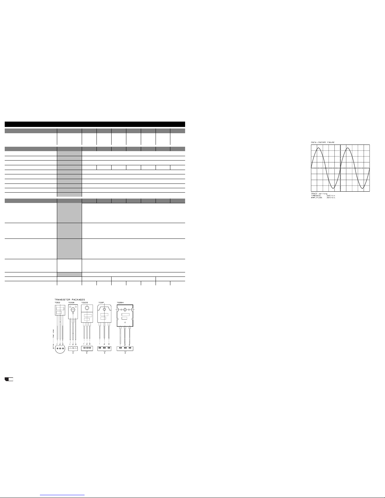
CHANNEL CHECK
• Be sure you have disconnected the load resistor.
• Increasing the input signal also the output signal raise accordingly,
it must be symmet-
rical without visible
distortion or oscillation
as shown in figure
(note: the figure is
representative don`t
refer to the levels
displayed). If there is
a distortion read the
section ADVICES.
• When the input sig-
nal exceeds -20dBu
(24Vpp on output)
the fans turn at their
maximum speed.
• Firstly you must
check the channel
without load, after-
wards you must repeat
the check with the loads attached, the following table reports the
approx. maximum level obtainable with this amp:
out level in level
no load 178Vpp +1.0dBu
1CH 4E 154Vpp +0.8dBu
2CH 4E 141Vpp +0.0dBu
Bridge 8E 278Vpp -0.5dBu
LEVEL METER ADJUSTMENT
• Check if the clip led lights at -2dBu on input (~130Vpp on output),
if necessary adjust the trimmers W301/2 on display board.
OFFSET ADJUSTMENT
• Set the input level at minimum (no signal), the output dc offset
voltage must be within range ±20mV, if necessary adjust the VR201
trimmer (for each channel) to be within this range.
BIAS ADJUSTMENT
• No bias adjustment is necessary for this amplifier circuitry; in any
case the amplifier has the possibility to adjust it if necessary. To check
properly the bias proceed as follows:
• Using a sinusoidal signal (1KHz or more) and the 4E load attached,
wait till the heatsink temperature reaches about 60°c.
• Turn down the signal at the smallest intensity you can read on your
oscilloscope trace connected at the amplifier output.
• Zoom in the crossing region using the amplitude, timebase and
trigger controls of your oscilloscope. If you see a distortion, try to
eliminate it adjusting the VR202 trimmer.
• Finally, set the input level at minimum and verify with the multimeter
attached across an emitter resistance (p.e. R232) that the dc voltage
doesn`t exceed 10mV.
ADVICES
• If you have determinate that the problem is a short on a rail, you
must check the output transistors.
• To determine which transistor devices are bad, use a soldering iron
to lift one leg of each emitter pin and measure the resistance across
emitter and collector of each device. Unsolder and lift one leg of each
base pin and check the base-collector resistance. Replace any device
that measure as a short.
• If all the transistors are OK, unsolder and lift one leg of each diode
and check them.
• Check the circuit board for open foil traces.
• Use the Multimeter to check the resistors, particularly the base and
emitter resistors of damaged transistor.
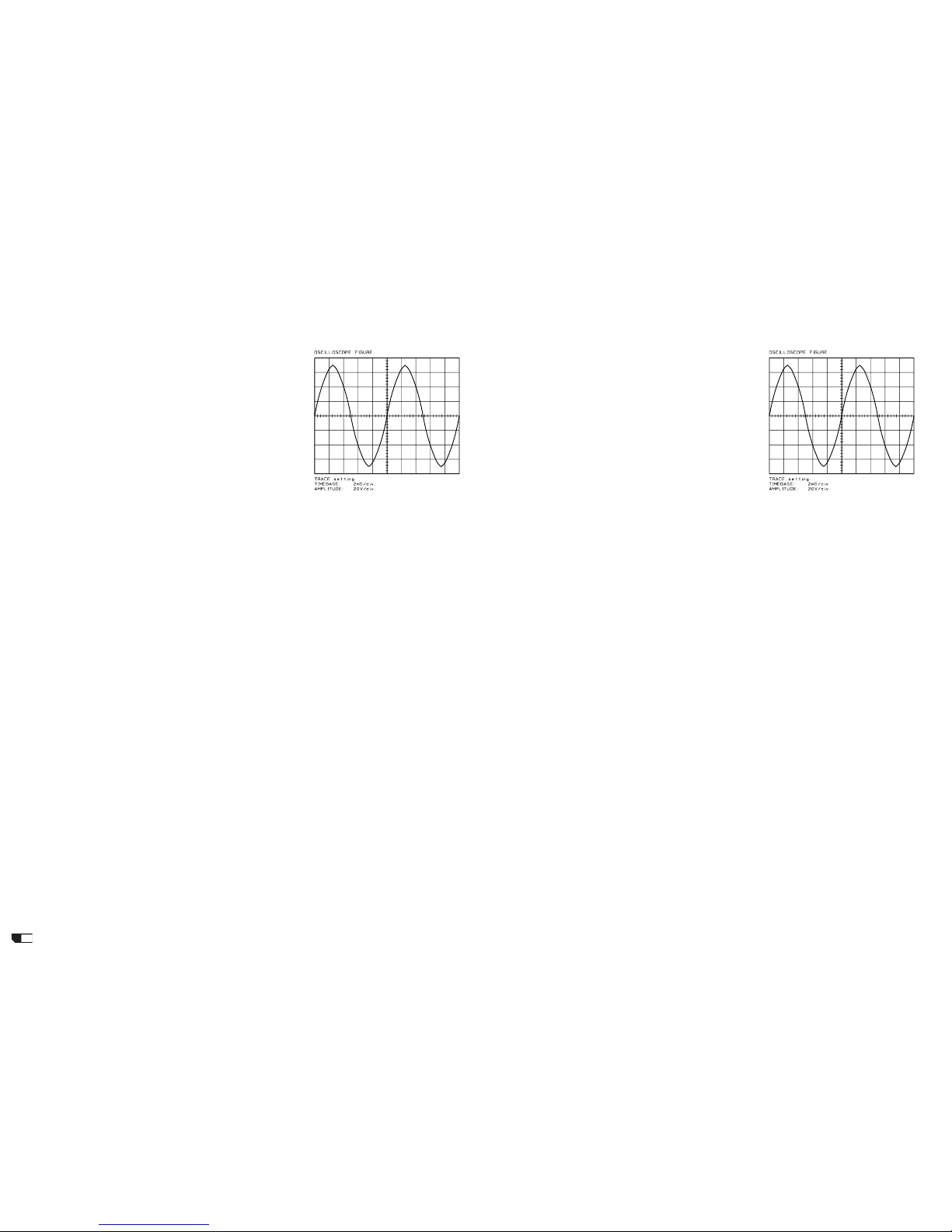
• If the input sinewave appears to be distorted during the negative
cycle, you can assume that the problem is located somewhere in the
circuitry of the positive rail.
• If the positive cycle appears distorted, you can assume that the
problem is in the circuitry of the negative rail.
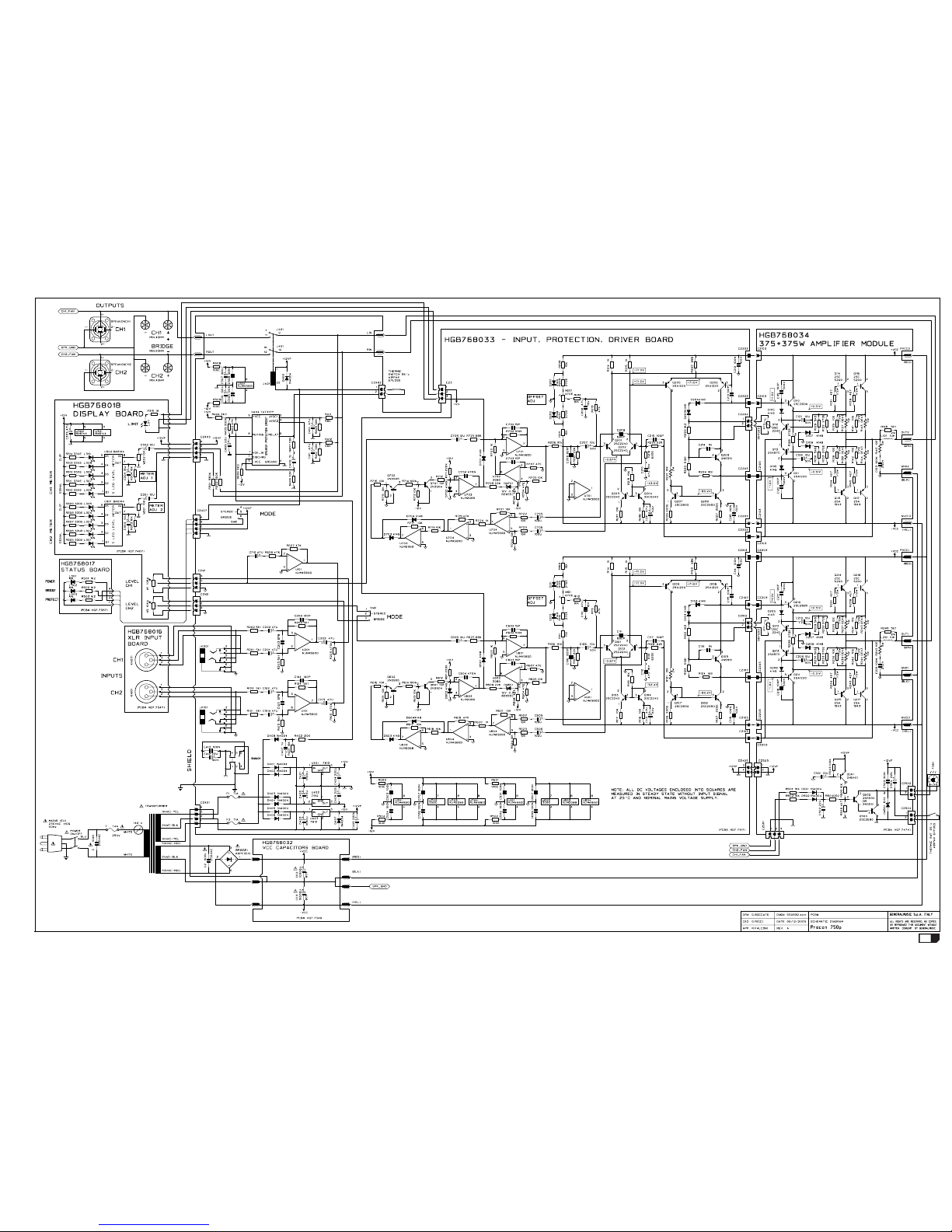
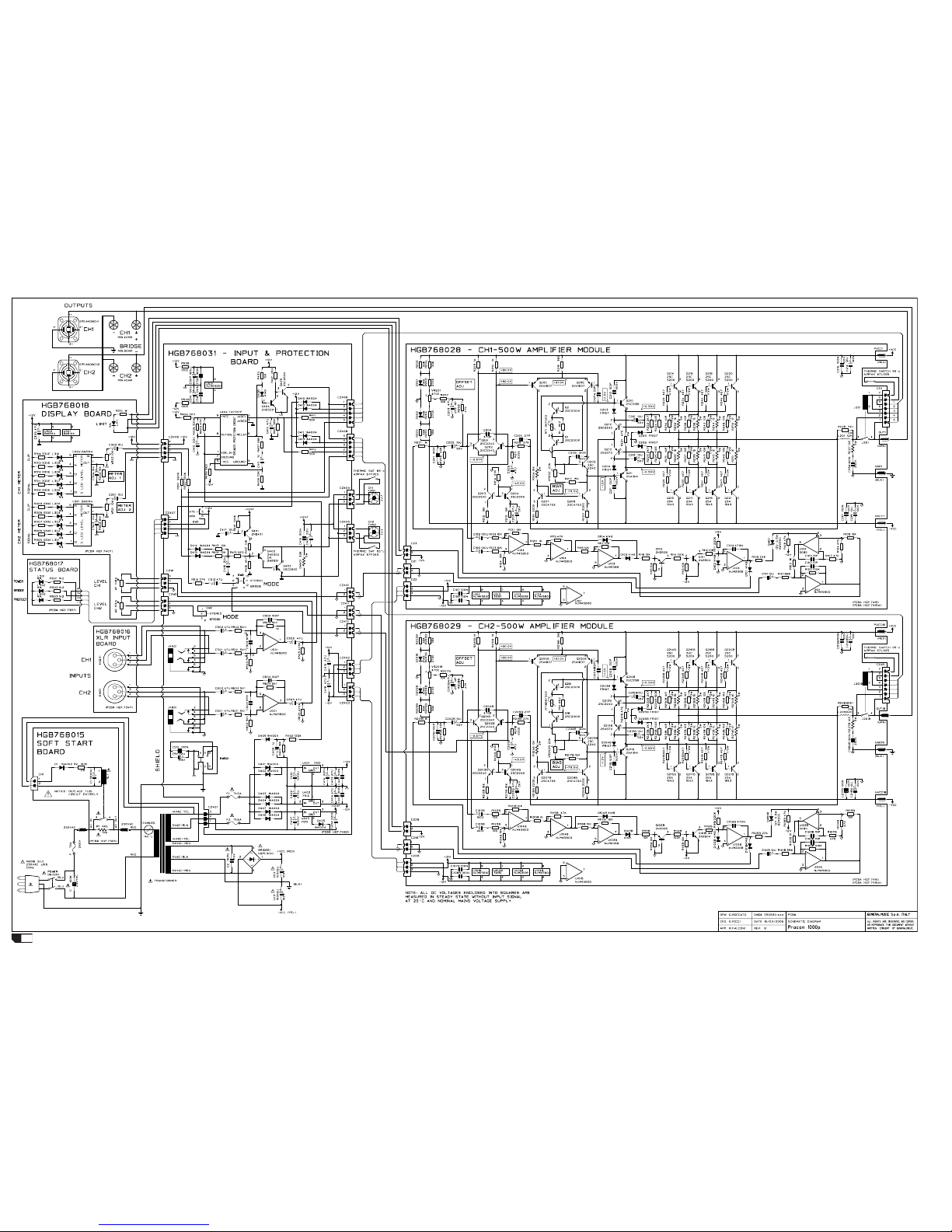
• The dc voltages printed on the schematics are measured with the
amplifier in steady state without input signal and nominal mains volt-
age supply, it can be useful to localize a damage.
PROCON1500p - Test procedures
PRECAUTION
• To prevent short circuit during any test, the oscilloscope must be
EARTH INSULATED, this occurs because some test require to connect
its probe to the amplifier output, non-compliance may cause damages
to oscilloscope inputs circuitry.
• Before removing or installing any modules and connectors, disconnect
the amplifier from AC MAINS and measure the DC supply voltages across
each of the power supply capacitors. If your measurement on any of
the caps is greater than 10Vdc, connect a 100E 100W resistor across
the applicable caps to discharge them for your safety. Remember to
remove the discharge resistor immediately after discharging caps. Do
not power up the amplifier with the discharge resistor connected.
• Do not check the amplifier with the speakers connected use the
appropriate load resistors only.
• BE CAREFUL increasing the Variac you must not exceed the nominal
mains voltage plus its tolerance (see specifications) any upper volt-
age can be cause of damage.
VISUAL CHECK
• Use compressed air to clear dust in the amplifier chassis.
• Before proceed to supply the amplifier check visually the internal
assembly, if appears an evident damage find the most possible rea-
sons that cause it.
• Check the wiring cables for possible interruptions or shorts.
• If the damage has burnt a printed circuit board don’t try to repair
it, replace with a new one.
TESTING GEAR
• Audio Generator
• Dual Trace Oscilloscope
• Digital Multimeter
• 4E 900W, 8E 1500W, 100E 100W resistors
• Variac
• Digital Thermometer (not indispensable)
SETUP
• Connect the Variac between the Mains and the amplifier and set
it at zero voltage.
• Turn full counter-clockwise the LEVEL potentiometers.
• Connect the audio generator to the channel inputs and set it to
1KHz 775mVrms (0dBu) sinusoidal signal.
• Connect the two scope traces to the amplifier outputs, before the
relay, and set them in DC at 50V/div. 2mS/div.
SUPPLY CHECK
• Verify with the Multimeter the insulation between the heatsinks and
all transistor collectors mounted on them; placing the multimeter tips
between the screw heads and the collector pins you can exclude an
erroneus reading due to the insulation of the heatsink anodization.
• Verify with the Multimeter the NTC (RT1) and R1 paralleled resistor
value, it must be about 7Kohm (at 25°c).
• Disconnect the amplifier module supplies of each channel (red and
yellow wires).
• Set the Variac to the nominal mains voltage, turn on the Amplifier,
then check with the Multimeter the AC supply voltages:
F1-F2 = 29±2Vac.
RED secondary wires = 145±8Vac.
• Re-set the Variac at zero voltage, turn off the amplifier and recon-
nect the supplies at each amplifier module.
• Set up the Variac slowly monitoring the oscilloscope screen, it should
display no signal; if you notice a DC voltage or a protection trips check
the amplifier as suggested in the ADVICES.
• As soon as the +12VF supply circuit reaches its nominal value,
all cooling fans run at their minimum and the speaker output relais
(J201-202) switch.
• When the Variac ac voltage reaches the nominal voltage verify the
DC supplies as follow:
+VCC = +97±6Vdc
-VCC = -97±6Vdc
U501 pin 8 = +12±0.5Vdc
U501 pin 4 = -12±0.5Vdc
U403 pin 3 = +12.5±0.5Vdc
• If one or more voltages don’t correspond, check the rectifiers, ca-
pacitors and transformers disconnecting them from circuitry.
CHANNEL CHECK
• Be sure you have disconnected the load resistor.
• Increasing the input signal also the output signal raise accordingly,
it must be symmet-
rical without visible
distortion or oscillation
as shown in figure
(note: the figure is
representative don`t
refer to the levels
displayed). If there is
a distortion read the
section ADVICES.
• When the input sig-
nal exceeds -20dBu
(24Vpp on output)
the fans turn at their
maximum speed.
• Firstly you must
check the channel
without load, after-
wards you must repeat
the check with the loads attached, the following table reports the
approx. maximum level obtainable with this amp:
out level in level
no load 189Vpp +1.0dBu
1CH 4E 166Vpp +0.7dBu
2CH 4E 154Vpp +0.2dBu
Bridge 8E 307Vpp +0.0dBu
LEVEL METER ADJUSTMENT
• Check if the clip led lights at -2dBu on input (~130Vpp on output),
if necessary adjust the trimmers W301/2 on display board.
OFFSET ADJUSTMENT
• Set the input level at minimum (no signal), the output dc offset
voltage must be within range ±20mV, if necessary adjust the VR201
trimmer (for each channel) to be within this range.
BIAS ADJUSTMENT
• No bias adjustment is necessary for this amplifier circuitry; in any
case the amplifier has the possibility to adjust it if necessary. To check
properly the bias proceed as follows:
• Using a sinusoidal signal (1KHz or more) and the 4E load attached,
wait till the heatsink temperature reaches about 60°c.
• Turn down the signal at the smallest intensity you can read on your
oscilloscope trace connected at the amplifier output.
• Zoom in the crossing region using the amplitude, timebase and
trigger controls of your oscilloscope. If you see a distortion, try to
eliminate it adjusting the VR202 trimmer.
• Finally, set the input level at minimum and verify with the multimeter
attached across an emitter resistance (p.e. R232) that the dc voltage
doesn`t exceed 10mV.
ADVICES
• If you have determinate that the problem is a short on a rail, you
must check the output transistors.
• To determine which transistor devices are bad, use a soldering iron
to lift one leg of each emitter pin and measure the resistance across
emitter and collector of each device. Unsolder and lift one leg of each
base pin and check the base-collector resistance. Replace any device
that measure as a short.
• If all the transistors are OK, unsolder and lift one leg of each diode
and check them.
• Check the circuit board for open foil traces.
• Use the Multimeter to check the resistors, particularly the base and
emitter resistors of damaged transistor.
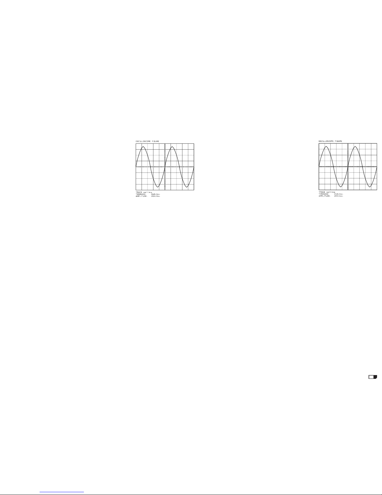
• If the input sinewave appears to be distorted during the negative
cycle, you can assume that the problem is located somewhere in the
circuitry of the positive rail.
• If the positive cycle appears distorted, you can assume that the
problem is in the circuitry of the negative rail.
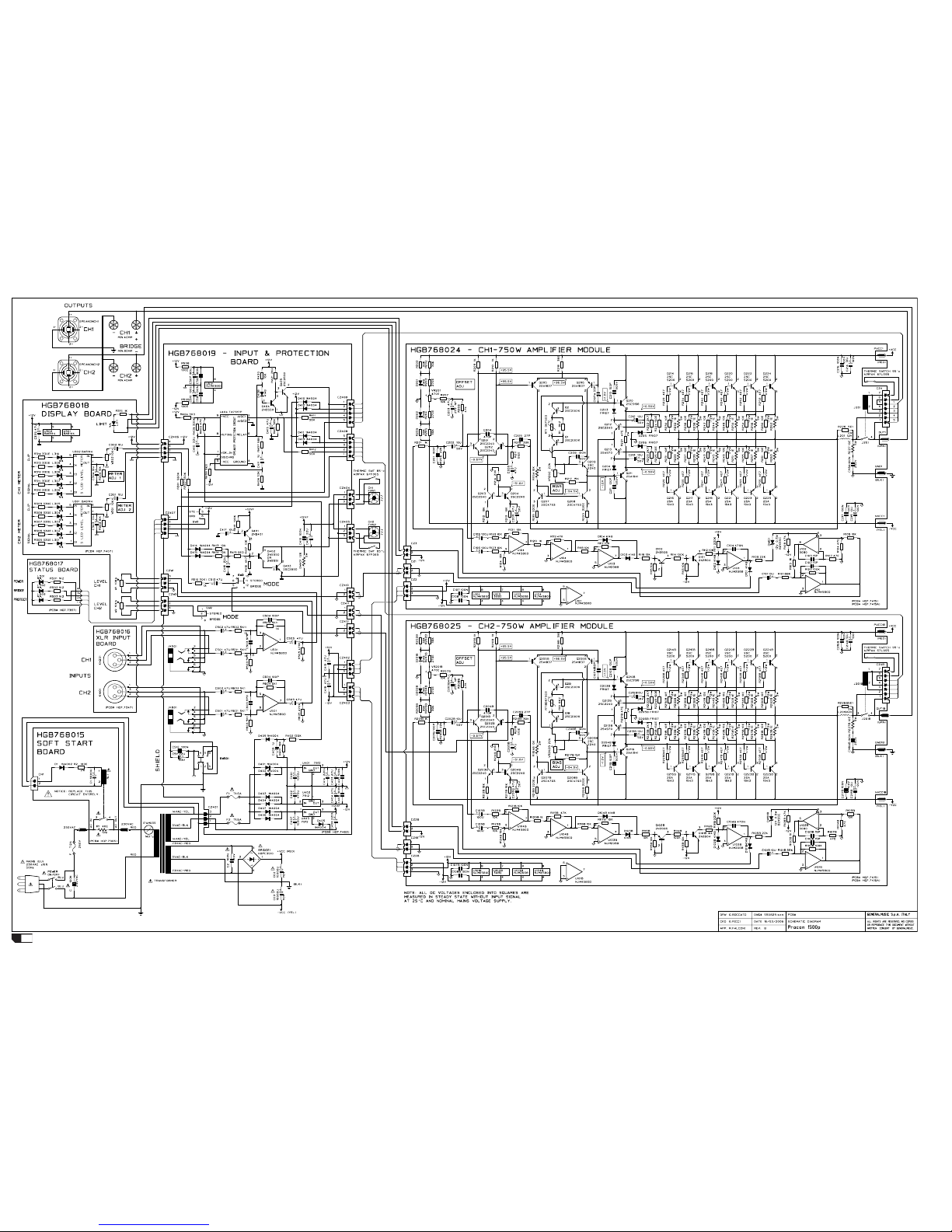
• The dc voltages printed on the schematics are measured with the
amplifier in steady state without input signal and nominal mains volt-
age supply, it can be useful to localize a damage.