LENCO LED-2217 User manual

55.5cm (22”) Full HD LED TV WITH DVB-S2,H.264,DVB-T/C AND CI
Model No.: LED-2217
For information and support, www.lenco.eu

1
Contents
SAFETY INFORMATION .............................................................................................................3
Headphone Warning....................................................................................................................................................... 4
Where to install.............................................................................................................................................................. 4
LED Screen..................................................................................................................................................................... 4
Unit and Accessories ................................................................................................................5
Getting Started.........................................................................................................................5
Front view....................................................................................................................................................................... 5
Remote Control ........................................................................................................................6-7
Aerial connection .....................................................................................................................8
Connecting the TV Antenna ............................................................................................................................................ 8
Connecting external devices ....................................................................................................8
HDMI Lead...................................................................................................................................................................... 8
SCART Lead.................................................................................................................................................................... 8
VGA Cable ....................................................................................................................................................................... 8
CONNECTIONS ............................................................................................................................................................. 10
PC connection............................................................................................................................................................... 10
VGA, HDMI PC Connection............................................................................................................................................ 10
Satellite connection...................................................................................................................................................... 10
Connecting an audio system ........................................................................................................................................ 11
Connecting a DVD player.............................................................................................................................................. 11
COAX Connection.......................................................................................................................................................... 12
HDMI Connection.......................................................................................................................................................... 12
SCART Connection........................................................................................................................................................ 12
USB Connection............................................................................................................................................................ 12
AV Connection .............................................................................................................................................................. 13
YPbPr Connection......................................................................................................................................................... 13
Common Interface Slot...........................................................................................................14
USING YOUR COMMON INTERFACE SLOT .................................................................................................................... 14
Auto installation setup ...........................................................................................................14
Power On / Off the LED TV............................................................................................................................................ 14
INSTALLATION MENU OPERATION ..........................................................................................15
INSTALLATION GUIDE .................................................................................................................................................. 15
TV SETTINGS Menu.................................................................................................................16
Auto Scan ..................................................................................................................................................................... 16
PROGRAMME EDIT ....................................................................................................................................................... 18
Signal Information........................................................................................................................................................ 18
Cl Information .............................................................................................................................................................. 18
Dish Setup .................................................................................................................................................................... 18
MENU SETTINGS.....................................................................................................................23
Picture menu................................................................................................................................................................ 23
SOUND menu................................................................................................................................................................ 24
Time menu.................................................................................................................... ........................................... 24
OPTIONS menu............................................................................................................................................................. 24

2
LOCK menu................................................................................................................................................................... 25
Multimedia Operation.............................................................................................................26
Basic Operation ............................................................................................................................................................ 26
1. Photo ........................................................................................................................................................................ 27
2. Music ........................................................................................................................................................................ 27
3. Movie ........................................................................................................................................................................ 28
4. Text ........................................................................................................................................................................... 28
TROUBLE SHOOTING GUIDE ....................................................................................................40
TECHNICAL SPECIFICATIONS .................................................................................................40
cations .......................................................................................................................................................... 40
DVD Operation 32-39
.........................................................................................................................
Recording Operation 29-31
.........................................................................................................................

3
Introduction
Thank you for purchasing this LED TV which has been designed and manufactured to give you many years of trouble
free service.
You may already be familiar with using a similar product but please take time to read these instructions which have
been written to ensure you get the very best from your purchase.
HDMI
terface) is the next generation of digital interface. Unlike conventional connec-
tions, it transmits uncompressed digital and audio signals using a single cabl
input via the HDMI socket on the back of the TV.
Safety is important
To ensure your safety and the safety of others, please read the safety precautions BEFORE you operate this product.
Disclaimer
The illustrations of the LED-TV, accessories and menus shown in this User’s Manual may differ from the actual prod-
uct.
SAFETY INFORMATION
IMPORTANT SAFETY INSTRUCTIONS - READ CAREFULLY BEFORE USE.
Take note of the following safety information which appears on the back of the TV.
CAUTION: TO PREVENT ELECTRICAL SHOCK, DO NOT REMOVE ANY COVER SCREWS, NO USER
SERVICEABLE PARTS INSIDE, REFER SERVICING TO QUALIFIED SERVICE PERSONNEL.
This symbol indicates that there are important operating maintenance instructions in the literature
accompanying this unit.
This symbol indicates that dangerous voltage constituting a risk of electric shock is present within this
unit.
Keep these instructions
Do not use this TV near water.
Clean only with a slightly damp cloth.
Do not block any ventilation openings.
Install in accordance with the supplied Quick Start Guide and this User Guide.
Protect the power chord from being walked on or pinched, particularly at plugs, and the point where it exits from
the TV.
Do not allow the power chord to overhang the edge of a table.
Unplug this TV during lightening storms or when unused for long periods of time.
WARNING! TO REDUCE THE RISK OF FIRE OR ELECTRICAL SHOCK, DO NOT EXPOSE THIS TV TO RAIN
OR MOISTURE. THE TV MUST NOT BE EXPOSED TO DRIPPING AND SPLASHING AND NO OBJECTS
FILLED WITH LIQUIDS SHOULD BE PLACED ON THE TV.
NOTE: No nak candles should be placed on the TV.
NOTE: When displaying the same still picture for more than 2 hours without any interruption, the picture contours of
the continuously displayed contents may remain visible on screen, i.e. a persistant image remains. The same applies,
when displaying for more than 2 hours:
the same background/wallpaper
logos, video games, computer images, Teletext
cont ratio (e.g. 4:3 format)
These do not represent any malfunction and will not be covered by the manufacturer’s warranty

4
This unit has been produced according to all current
safety regulations. The following safety tips should
safeguard users against careless use and the dangers
connected with such use.
Although this appliance has been carefully manufac-
tured and rigorously checked prior leaving the fac-
tory, as with all electrical appliances it is possible for
problems to develop. If you notice smoke, an excessive
build up of heat or any other unexpected phenomena,
you should disconnect the plug from the mains power
socket immediately.
Ensur y ventilated! Never
place next to or underneath curtains!
The mains plug or appliance coupler is used as the
disconnect device, the disconnect device shall remain
readily operable.
This set should only be connected to a mains power
supply which matches that stated on the label on the
rear of the TV - do not attempt to connect it to any
other type of supply.
The socket - outlet must be installed near the equip-
ment and easily accessible.
To prevent overload, don’t share the same mains sup-
ply socket with too many other items of equipment.
Apparatus with Class 1 construction shall be con-
nected to a mains socket outlet with a protective earth
connection.
Keep away from rodents. Rodents enjoy biting into
el exes.
Always hold the plug when pulling out the plug from
the mains supply sock ex, the
ex can become overloaded and cause a short circuit.
Set up the unit so that no one is able to trip over the
ex.
Do not place heavy it x, which may dam-
age it.
Take not ex cannot be reached and pulled
by young children, avoiding injury.
Do not set up the unit near to heat sources. The casing
ex could be damaged by the impact of heat.
The screen is made of plastic and can break if damage
is done to it. Be careful when collecting sharp edged
plastic splinters to avoid injury.
Avoid placing the unit on any surfaces that may be
subject to vibrations or shocks.
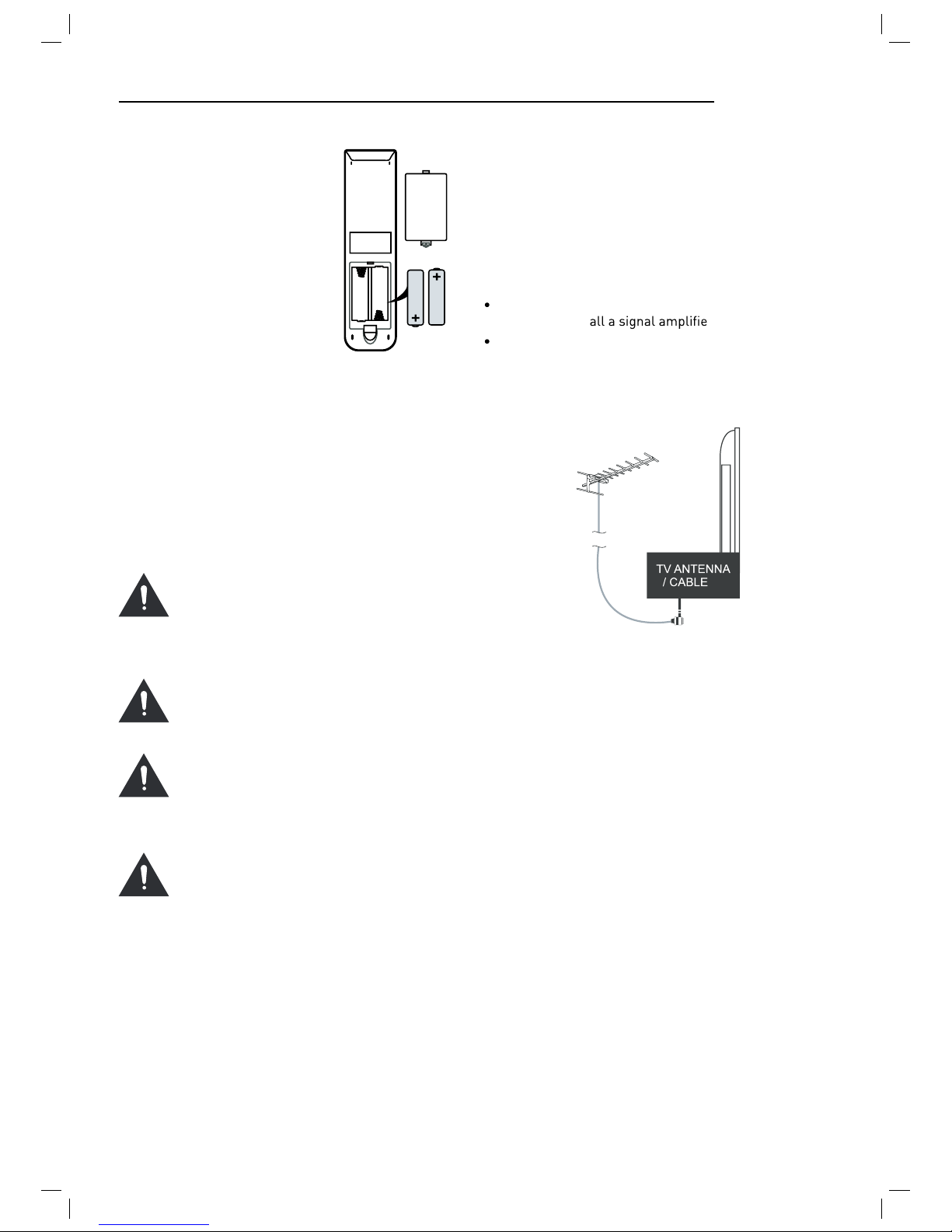
To protect the unit during a thunderstorm unplug the
AC power cable and disconnect the aerial. Caution: Do
not touch the aerial (RF) connector.
When you leave your home for long periods of time,
unplug the AC power cable for safety reasons.
The unit becomes warm when in operation. Do not
place any covers or blankets on the unit in order to
prevent overheating. The ventilation holes are not to
be blocked. Do not set up near radiators. Do not place
in direct sunshine. When placing on a shelf leave 5 cm
(2”) free space around the whole unit.
Do not allow water or moisture to enter the TV. Do
NOT use in wet or moist areas such as Bathrooms,
steamy kitchens or near swimming pools.
Do not use this unit when moisture condensation may
occur
Any repairs must be c rsonnel
only.
Do not open this unit. A non-expert attempting to re-
pair the unit could be dangerous and potentially cause
re hazard.
Liquids spilt into the unit can cause serious damage.
Switch the set OFF and disconnect the mains power
supply, then c ce person before
attempting to use the unit again.
Do NOT remove the safety covers. There are no use-
able or serviceable parts inside. You may invalidate the
warranty rsonnel must only service this
apparatus.
Do NOT tap or shake the screen, you may damage the
internal circuits. Take good care of the remote control,
do not drop.
Never plac rces on or
close to the TV.
High temperatures can melt plastic and lead t res.
To clean the TV use a soft dry cloth. Do NOT use sol-
vents or petr For stubborn stains, you
may use a damp cloth with dilute detergent.
Headphone Warning
Loud music can damage your hearing
irreversibly, therefore do not set the volume
to a high level when listening through
headphones, particularly for lengthy
listening periods.
Where to install
Locate the television away from direct sunlight and
strong lights, soft indirect lighting is recommended for
comfortable viewing. Use curtains or blinds to prevent
direct sunlight falling on the screen. Place the TV on a
sturdy platform of which the surfac
steady. This will prevent it from falling over.
Make sure the television is located in a position where it
cannot be pushed or hit by objects, as pressure will break
or damage the screen, and so that small objects cannot
be inserted into the ventilation slots or openings in the
cabinet.
LED Screen
The LED display panels are manufactured using an
extremely high level of precision technology, however
sometimes some parts of the screen may be missing
picture elements or have luminous spots. This is not a
sign of malfunction.

5
Unit and Accessories
TV set Remote Control Batteries
for Remote
Control
Converter cable for
AV and YPbPr video
Getting Started
Front view
Packaging materials are no toys. Please keep away from
children. Plastic bags can cause suffocation when pulled
over the head.
This Television is designed to work with any DTV Antenna,
Analog or Digital cabl xed Satellite Dish aligned
with Astr ted with a universal LNB.
Other Dishes and LNBs can be used but full set up is
required. The Television is preset for the abov xed
dish/LNB and when quickstart is used Astra 19.2E will be
instantly tuned without need of a “search”
Mains adapter
Mains adaptor
Mains cable
Remote Control window
INPUT
MENU
CH+
CH-
VOL+
VOL-
POWER
1). (IR) Infrared Receiver: Receives IR signals from the remote control.
(Power on/Standby)LED Indicator: Press POWER to turn on and off.
Indicator on(Blue) Standby mode
Indicator on(Off) Power on mode
2).The functions of the buttons are described as bellows:
INPUT: Press to display the input source menu.
MENU: Press to display the OSD menu, press again to exit the menu.
CH+/-: Press to scan through channels.
VOL+/-: Press to adjust the volume.
POWER: Turn on/standby the TV set.
The effective receiving range for the signal is 5-8 metres from the front of the remote
control window, and 300to the left or right side and 200above or below the remote control
window.
POWER MUTE
REC
TV/AV
MENU
TV/TXT CANCEL REVEAL NICAM/A2
HOLD SIZE SUBPAGE INDEX
PICTURE EPG
SOUND SLEEP
SCREEN
EXIT
HCLOV
FAV
1234
5678
90
DISPLAY
REC LIST CH/LIST SUBTITLE REPEAT
OK

Remote control
6
The remote control is using Infra-Red(IR). Point it towards the front of the TV. The remote
control may not work correctly if it is operated out of range or out of angle.
POWER: Turn the TV on/standby.
MUTE: Press to mute the sound, press again or press
VOL+ to unmute.
REC LIST: Record List.
CH/LIST: Display the programs list.
SUBTITLE: Turn on/off the subtitle display in DTV mode
REP: Repeat playing the title or chapter.
CURSOR KEYS OK
Allows you to navigate the on-screen menus and adjust the
system settings to your preference.
NUMBER BUTTONS
Press0-9 to select a TV channel directly when you
are watching TV.
Return to the previous channel viewed.
INPUT: Press to display the input source menu.
DISPLAY: Press to display the current mode’s information.
MENU: System setup menu.
EXIT: Exit the OSD menu.
FAV: Display the favorite program list.
REC : Press to start record the program in DTV mode.
: Previous chapter.
: Next chapter.
: Fast reverse.
: Fast forward.
: Stop program.
: Pause program.
: Play program.
ETUMREWOP
REC
INPUT
MENU
TV/TXT CANCEL REVEAL NICAM/A2
HOLD SIZE SUBPAGE INDEX
PICTURE EPG
SOUND SLEEP
SCREEN
EXIT
HCLOV
FAV
1234
5678
90
DISPLAY
REC LIST CH/LIST SUBTITLE REPEAT
OK

Remote control (continued)
7
CH / : Scan through channels.
VOL / : Adjust the volume.
PICTURE: Select the picture mode.
NICAM/A2: TV Nicam/A2 select.
SOUND: Select the sound mode.
SLEEP: Standby timer.
SCREEN: Turn on/off the screen.
TV/TXT: Turn off/on the Teletext display.
CANCEL: Cancel the Teletext display.
REVEAL: Reveal any hidden text.
HOLD: Hold or carry on the current subpage.
SIZE: Press to see top half of page double size,
Press again to see the bottom
half of page double size. Press again for normal size.
SUBPAGE: Press to enter subpages, pressagain to cancel.
INDEX: Go to index.
Colour buttons:Short cuts-follow the coloured links in the text
ETUMREWOP
REC
INPUT
MENU
TV/TXT CANCEL REVEAL NICAM/A2
HOLD SIZE SUBPAGE INDEX
PICTURE EPG
SOUND SLEEP
SCREEN
EXIT
HCLOV
FAV
1234
5678
90
DISPLAY
REC LIST CH/LIST SUBTITLE REPEAT
OK
EPG: To show the Electronic Program Guide during no-menu
state only in DTV mode.

8
Installing Batteries in the
Remote Control
1. Remove the battery compart-
ment cover at the rear of the
remote control by pushing
the retaining clip forward and
pulling up.
2. Install the supplied batter-
ies, ensuring the polarity
matches what is shown in the
battery compartment.
3. Replace the battery compart-
ment cover.
Aerial connection
WARNING! ENSURE THE TV AND ALL ANCILLARY
EQUIPMENT IS UNPLUGGED FROM THE MAINS BEFORE
MAKING ANY CONNECTIONS!
Connecting the TV Antenna
Connect the TV antenna to the aerial socket with a 75
ohm co-axial plug. For best results use a high gain TV
aerial, preferably roof or loft mounted.
To improve picture quality in a poor signal area, pur-
chase and inst r.
If the antenna needs to be split for two TVs, use a 2-
Way Signal Splitter (not supplied).
Using the Remote Control
To use the remote control point it at the TV and press the
required buttons. You must be within 6 meters and at an
angle of less than 30 degrees from the center of the TV.
NOTE: Sunshine or other strong light sources may inter-
fere with the signal from the remote control. In this situa-
tion turn the TV away from the light source.
WARNING! DO NOT LEAVE BATTERIES IN
THE REMOTE CONTROL FOR EXTENDED
PERIODS AS THEY CAN LEAK OR CORRODE
CAUSING DAMAGE TO THE REMOTE CON-
TROL. CHECK THEM PERIODICALLY AND
REPLACE THEM AS REQUIRED.
WARNING! DO NOT MIX BATTERY TYPES.
WHEN INSERTING BATTERIES, REPLACE
ALL BATTERIES AT THE SAME TIME. DO
NOT MIX OLD AND NEW BATTERIES.
WARNING! EXHAUSTED BATTERIES MUST
BE TREATED WITH CARE AND DISPOSED
OF ACCORDING TO ANY SAFETY OR RECY-
CLING REGULATIONS IN FORCE IN YOUR
LOCAL AREA, NEVER DISPOSE OF BATTER-
IES INTO GENERAL WASTE, OR FIRE.
WARNING! NEVER EXPOSE BATTERIES TO
EXCESSIVE HEAT SUCH AS SUNSHINE, FIRE
OR THE LIKE.
Connecting external devices
This instruction manual shows the simplest and most ef-
fective way of connecting your TV to ancillary equipment.
Alternate methods are listed below.
HDMI Lead
You can connect this TV to a compatible device using a
HDMI lead. This method will give the best picture.
Connect the cable from the HDMI equipment to the TV
HDMI socket.
SCART Lead
You can connect this TV to a compatible device using
a SCART lead. The connection uses component video
signals, i.e. the red, green and blue (RGB) content of the
video are sent on separate signals.
VGA Cable
You can use your TV as a monitor for your personal com-
puter by using a VGA cable. Sound from your personal
computer may also be played through the TV.

9
Connecting external devices (continued)
Output t
Common Int fac
Sat t
Output t
POWER USB HDMI SCART PC-IN VGA YPbPr AV
MINI MINI
Satelliten Receiver
oder Blue-Ray DVD
USB device
Converter cable
audio
DVB-S2

10
Connecting external devices (continued)
CONNECTIONS
Name Function Description
POWER Connect to power supply
HDMI Connect to the HDMI output of your
DVD or Satellite Box
DVB-S2 Connect to Satellite signal
VGA (PC IN) Connect to the PC VGA output to dis-
play PC graphics
PC-IN PC Audio input
Mini YpbPr Connect to the YPbPr output on exter-
nal devices
Mini AV Connect to AV output on external
devices
SCART Connect to the SCART input / output
of external devices
RF Connect to TV signal cable
Head phone Connect Head phone
CI CI slot (Pay as you view card slot)
Coax Output t
USB Media playback and PVR
Caution:
Before connecting external devices:
Makes sure to disconnect the appliances from the
power supply in order to avoid any potential damage
from occurring.
Make sure to establish the required connection.
Make sure that the connectors are properly and cor-
rectly attached before connecting the appliances to the
power supply.
PC connection
As PCs are sometimes still supplied with a ‘conventional’
CRT monitor, you may need to adjust the display set-
tings of your PCs graphics card, otherwise the pictures
may not appear correctly. Switch on your PC (still with
your original monitor connected) now select the screen
resolution, and select 60Hz refresh rate. Switch off your
PC, then connect it to your TV while both appliances are
still switched off.
VGA, HDMI PC Connection
Use a PC-VGA cable (not supplied) to connect the TV to
your PC. You can also use an HDMI cable to connect to
your PC (if your PC Graphic card supports HDMI). When
the HDMI cable is used, the PC audio cable is no longer
required. If you use the HDMI to DVI cable, you will need
to use the PC audio cable. Connect all cables carefully
and do not bend or break the connector pins.
When using the VGA cable
Switch on the TV
Switch on the PC
Select PC/VGA as input source
When using the HDMI cable
Select HDMI as input source
VGA cable
HDMI to DVI cable
Audio cable
HDMI to HDMI
(All illustrated cables are not supplied)
Satellite connection
DVB-S/DVB-S2 Signal
Connect the DVB-S/DVB-S2 signal to the SATELLITE LNB
on the TV SET. Select the SATELLITE input source using
the INPUT button on the remote control.
DVB-S2

11
Connecting Video camera and Video recorder
Video camera
Connect the AV cable to the TV and to the video cam-
era.
Turn on both video camera and the TV.
Select AV/CVBS source
You can now see the playback picture from the video
camera. Note:
To connect the video camera using other cables, refer
to the video camera instruction manual.
Video recorder
Connect the Scart cable to the TV and video recorder.
Turn on both video recorder and the TV.
Select Scart source
You can now see the playback picture from the video
recorder.
Note:
To connect the video recorder using other cables, refer
to the video recorder instruction manual.
Scart cable
Video recorder
Video camera
(Mini AV cables is supplied)
Connecting an audio system
You can supply the TV sound to the stereo system (A) with
the Scart socket. Use a special Scart cable SCART to RCA.
(Please consult y structions for details). If you
have a surr coder (B) Use the
Scart cable or the special Scart cable Scart to RCA.
Scart to RCA cable
Scart cable
(All illustrated cables are not supplied)
Connecting a DVD player
Connect a DVD player using either a SCART cable or the
HDMI cable. (only if your external equipment supports
HDMI).
HDMI to HDMI
SCART
(All illustrated cables are not supplied)
When using the SCART cable
Switch on the TV
Switch on the DVD player
Select SCART as input source
When using the HDMI cable
Select HDMI as input source
Use Scart adapter cable
Mini Audio and Video transfer
cable

POWER USB HDMI SCART PC-IN VGA YPbPr AV
MINI MINI
12
COAX Connection
TV Back
Coax Cable
Connect t evice to the COAX output jack
on the TV.
HDMI Connection
TV Back
elbaCIMDH
DVCR Back
SCART Connection
HDMI connection allo to t ansf cont ol signals th ough one cable only. These signals a e
tansf ed in digital.
DVCR Back
DVCR
Connect the SCART connect to the ext tem
and the SCART connect V. The SCART lead
ope at connection. If the tv does not
select the SCART input automatically, select SCART using
the SOURCE button on the emote cont v.
Sc cable
USB Connection
ve in t lect the USB channel sou ce using the SOURCE button on the emote
cont ol.
USB P
TV Back
DVCR
POWER USB HDMI SCART PC-IN VGA YPbPr AV
MINI MINI
POWER USB HDMI SCART PC-IN VGA YPbPr AV
MINI MINI
DVB-S2

13
TV Back
Audio and video cable (RCA)
Mini audio and video
transfer cable
DVD or VCR back
Connect the VIDEO and AUDIO output jack of the DVD or VCR to the VIDEO jacks on the TV set using the RCA cable.
Match the jack colors: Video is yellow, Audio left is white, and Audio right is red. Select the AV input source via the
SOURCE button on the remote control.
YPbPr Connection
Connect the YPbPr output of the DVD or VCR to the YPbPr input on the TV set. Connect the Audio output of the DVD or
VCR to the Audio input jacks on the TV set using the RCA cable.
Match the jacks colors : Y is green, Pb is blue, Pr is red, Audio left is white, and Audio right is red. Select YPbPr input
source via the SOURCE button on the remote control.
TV Back
Audio video cable (RCA)
Audio cable
Mini video transfer cable
DVD or VCR back
DVD or VCR
DVD or VCR back
DVD or VCR
DVD or VCR
USB HDMI SCART PC-IN VGA YPbPr AV
MINI MINI
USB HDMI SCART PC-IN VGA YPbPr AV
MINI MINI
AV Connection

14
CI Slot
CAM
Smart Card
1. Turn on the TV and ensure ‘DTV’ Source is selected.
2. If the CAM is detected the TV will display the following
message on the screen. “Common Interface Module
inserted” wait for a few moments until the card is
activated.
3. Select the relevant digital Pay Per View channel.
4. Detailed information on the Smart Card in use is dis-
played
5. Press the Ok button to access the card menu. Refer to
the Module Instruction Manual for setting details.
6. When the module is removed, the following message
will appear on the screen. “Common Interface module
removed”.
Auto installation setup
Power On / Off the LED TV
To turn on the LED TV
Press the power button on the LED TV or the POWER but-
ton on the remote control, the standby indicator will light
green.
Common Interface Slot
USING YOUR COMMON INTERFACE SLOT
Common Interface
The Common Interface (CI) slot is designed to accept
the Conditional Access Module (CAM) and Smart Card
in order to view the pay TV programmes and additional
services. Contact your Pay Per View TV service provider
to get more information about the modules and subscrip-
tions.
NOTE: Conditional Access Module and Smart Cards are
sold separately.
WARNING! SWITCH OFF YOUR TV BEFORE ANY MODULE
IS INSERTED INTO THE COMMON INTERFACE SLOT,
THEN ADD THE SMART CARD TO THE CAM.

15
INSTALLATION MENU OPERATION
INSTALLATION GUIDE
When powering up f rst time the Installation Guide
Will appear on screen.
Choose the language using buttons and then press
OK
Choose the service to install using the buttons and
then press ok.
You will now see the quick-start menu. Ensure that your
signal cable is connected to the TV and press OK 2 times.
The TV will now install the chosen service and tune all
available channels.
You can only install one service at a time but you can re-
turn at any time to install additional services by pressing
the QUICKSTART button on the handset
ATV will install an Analogue Television cable service
DTV will install a Digital Terrestrial Television service
(DVBT)
During the channel search this menu is displayed show-
ing the progress.

16
TV SETTINGS Menu
All the above installations can also be accessed through
the Main Menu system. In the TV Settings menu.
To access the correct service you need the TV to be in the
correct mode, ATV, DTV, cable or Satellite.
Select the mode either from the handset or from the
source menu.
When you are in the correct mode, press Menu button on
the remote control and enter the TV Settings Menu
Press MENU button to display the main menu, use
left/right buttons to select EINSTELLUNGEN menu, press
OK or down button to enter the menu. Press MENU or up
button to return to the main menu.
NOTE: TV SETTINGS can only be selected under the ATV/
DTV/SATELLITE/CABLE modes, it is disabled whilst in all
other modes.
ATV / CABLE SETTINGS
DTV / DVB-T SETTINGS
SATELLITE / DISH SETTINGS
DIGITAL CABLE (DVBC) SETTINGS
Auto Scan
In the Auto Scan menu there are 3 options for you to se-
lect from: DVB Select type, Country and Tune Type.
Press / to select DVB Select type, Country and Tune
Type, press OK to start scanning.
If you select ATV+D rst 50% of the processing is
for ATV tuning, while the second 50% represent DTV tun-
ing. When ATV tuning, you can press MENU to Skip ATV
tuning and start DTV tuning or press EXIT to exit tuning.
During the channel search this menu is displayed show-
ing the progress.
DTV
Input Source
CADTV
SATELLITE
ATV
SCART
YPbPr
PC
HDMI
AV
USB

17
Unlike QUICKSTART the satellite search will search the
whole satellite for channels and will not be instant.
Also the channels will appear in the order on the satellite
and not the pre-set order.
Auto search replaces any previous searched channels
with those of the new search. To add an extra satellite if
you have a suitable Dish/LNB/Switch you must use the
Dish Installation menu.
DTV Manual Tuning
You can manually tune DTV channels in the TV SETTINGS
menu. Press the Left/Right arrow buttons to select the
channel you wish to tune, then press OK button to scan
for the channel.
CADTV Manual Tuning
You can manually tune CADTV channels in the TV SET-
TINGS menu.
Frequency
Select Frequency using the buttons.
Symbol (ks/s)
Select the Symbol (ks/s) using the buttons.
QAM Type
Select the QAM Type using the buttons
ATV Manual Tuning
You can manually tune ATV channels in the TV SETTINGS
menu.
Storage to
Press the buttons to change the numbered location
of the found channel.
System
Select the system using the buttons.
Current CH
Displays the current channel number, press the buttons
to choose the channel you wish to modify.
Search
Press the buttons to scan through the frequencies to
ew channels.
Fine tune
In case of bad reception, you can press the buttons to
mak stments to the tuning. After manual tun-
ing is complete, please press the RED button to save any
found channels.

18
PROGRAMME EDIT
Use up/down keys to select program edit. Press OK or
Right button to enter the menu. Use up/down buttons to
navigate through the menu
Delete
Press the RED button to delete the highlighted channel, a
red circle will appear next to the channel name.
Press the RED button again to c lete.
Press the MENU to return to the main menu.
Move
Press to select the channel, press yellow button to
enter the move mode, then press to move the chan-
nel location, press yellow button again or press OK to
c
Press MENU to return to the main menu.
Skip
Press to select the channel you wish to skip.
Press the BLUE button, a logo will appear next to the
channel name and the channel will be skipped when you
scroll through the channels.
Press the BLUE button again on the highlighted channel
to disable the skip function. Press MENU to return to the
main menu.
Rename (Only available in ATV)
Modify current channel name.
Press the button to enter RENAME mode, then use
the buttons to change name. Press green button
again or press menu button to c
Signal Information
Only available in DTV mode, Signal Information includes:
channel /network/modulation/quality /strength.
Cl Information
When insert CI Module, display CI Information.
Dish Setup
1. If you do not hav xed dish aligned to Astra 19.2E
ted with universal LNB you will need to use this
section.
2. If you hav ed Dish aligned to a different Satellite
or with a different LNB you will need to use this sec-
tion.
3. If you have a motorised Dish with a DiSEqC rotator
and wish to tune more than one satellite you will need
this section.
4. If you are on a DiSEqC switch system you will need
this section.
rst 2 installations can be done by most people so
long as you know what satellite your dish is aligned with
ted with.
Installation of 3 & 4 require an experienced user or
engineer.
To set a different Satellite or LNB
Select Satellite mode, press MENU key, navigate down to
the Dish Setup option, press OK. You will see the Satellite
Dish Setup menu.
To set Multiple Satellites and LNBs (only possible
on multi-LNB dish, switch systems)
Use buttons to select the satellite to which your dish
is aligned. Press OK. An arrow will display against the
chosen satellite.
Press button to navigate to LNB section of the menu.
Select the LNB type and settings for your LNB. Press the
blue Key to search the satellite channels.
Press the Exit button and the button to select the sec-
ond satellite.
Use buttons to select the second satellite to which
your dish is aligned. Press OK. An arrow will display
against the chosen satellite.
FAV
Select a program, press FAV button to set or delete the
channel.
program as the favorite

19
Press button to navigate to LNB section of the menu.
Select the LNB type and settings for your second LNB
and switch settings.
Press the blue Key to search the satellite channels.
A full description of the advanced Dish set up for
multiple satellites using DiSEqC switches and DiSEqC
positioner follows. This should only be attempted by
experience users.
The Dish set up main menu page displays the main inter-
face. The interface consists of Satellite List, Transponder
list and Dish/LNB parameter list
Satellite Edit
Press the Green button to enter the edit menu Edit pa-
rameters as described below
No. The current list number of the selected satellite Sat-
ellite name. Edited from the onscreen keyboard press
button to enter.
Satellite List
The Satellite list displays the satellite names.
In the input frame, use and OK button to select
characters.
Extend: Extended characters
Caps On: Change character case. Press OK button to
select.
Back: Delete letters, press OK to c
OK: Sure to set the naming of the satellite, and return to
Edit Menu
Cancel: Return directly back to edit menu.
Input Frame (On-screen keyboard)
Longitude Direction: Added to determine the location of
the satellite. Use the arrow buttons to select West/
East.
Longitude Angle: Input Longitude. By moving the cursor
buttons to enter the satellite longitude.
Band: band selection. Press to select.
Delete Satellite menu
Press the YELLOW button, the c -
pear. Press OK to delete.
Add Satellite
Press the RED button to see the Add menu.
NO: This is the list placing number. This number cannot
be manually edited.
Table of contents
Other LENCO LED TV manuals

LENCO
LENCO DVL-2695 SILVER User manual

LENCO
LENCO DVL-2690 User manual

LENCO
LENCO DVL-2261 User manual

LENCO
LENCO LED-3901-4K Manual

LENCO
LENCO DVL-1662BK User manual

LENCO
LENCO LED-2250 User manual

LENCO
LENCO LED-2215 User manual

LENCO
LENCO DVL-2458 BLACK User manual

LENCO
LENCO DVL-2461 User manual

LENCO
LENCO LED-2213 User manual