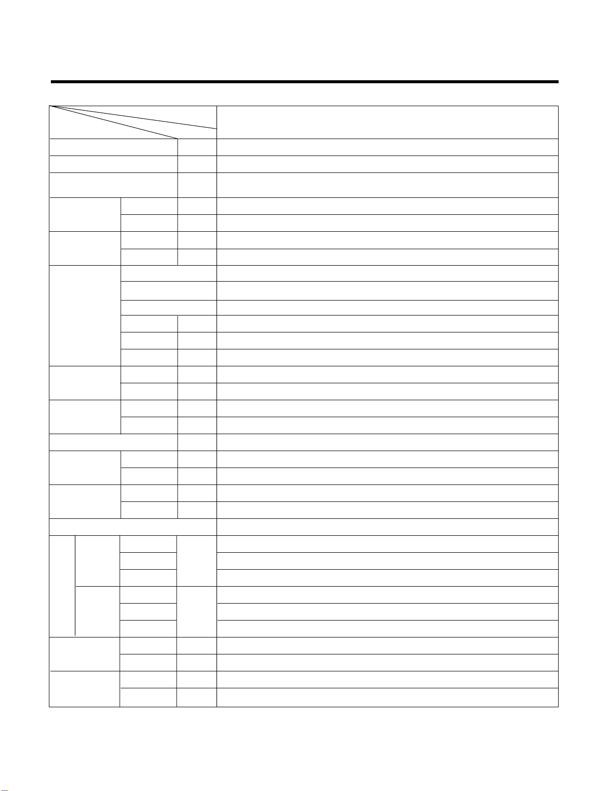
Lennox VHA 30 User manual

INSTALLATION
OPERATING&
MAINTENANCEMANUAL
FLOOR STANDING
SPLIT UNIT
English
July 2002


Contents
Functions 3
Product Specifications 6
Dimensions 7
Refrigeration Cycle Diagram 7
Wiring Diagram 8
Operation Details 9
Installation of Indoor, Outdoor Unit 15
Test Running 26
Cycle 28
Cycle Troubleshooting Guide 31
Electronic Parts Troubleshooting Guide 32
Electronic Control Device 35
Schematic Diagram 36
Exploded View and Replacement Parts List 37
–2–

–3–
Functions
Indoor Unit
Power Switch ON/OFF
Operation Mode Control
Sensing the room temperature
Controlling the room temperature
Starting Current Control
Sensing Heat Exchanger Temperature
Timer Delay Safety Control
Indoor Fan Speed Control
Temperature Setting
Airflow Direction Control
Room temperature Display
Timer Control
Sensing Discharge Air Temperature
• Cooling, Soft Dry, Auto, Fan Cooling Model •
Cooling, Heating, Soft Dry, Fan Heat Pump Model
• Room temperature sensor (Thermistor)
• Maintains the room temperature in accordance with the setting temperature.
• Indoor fan is delayed for 3 sec at the starting.
• Heat exchanger temperature sensor (Thermistor)
• Restarting is inhibited for approx. 3 minutes.
• High, Med, Low 3HP, 5HP • High, Low 8HP
• Up : up to 30°C
• Down : down to 16°C
• Airflow direction Automatic and Manual control
• Low, 10° ~ 35°C, Hi
• Off Timer (1, 2, 3....7 hour)
• Discharge temperature sensor <Thermistor>
• Apply Heat Pump Model Only.

–4–
Remote Control
Operation ON/OFF
Operation Mode Selection
• Cooling, Soft Dry, Auto, Fan Cooling Only Model
• Cooling, Heating, Soft Dry, Fan, E/heater Heat Pump Model
Fan Speed Selection
Setting the temperature
Timer Control
Airflow Direction Control
• High, Medium, Low
• High, Medium
•UporDown
• Off Timer(1, 2, 3...7 hour)
• Airflow direction Auto-Swing and Manual control

–5–
Outdoor Unit
Deice Control
Outdoor Fan Speed Control
Sensing Heat Exchanger Temperature
Sensing Discharge Pressure For Compressor
• De-ice PCB
• One speed
• Heat exchanger temperature sensor (Thermistor)
• Discharge pressure sensor (High Pressure Switch)

Product Specifications
–6–
POWER SUPPLY Ø, V, Hz
COOLING CAPACITY Btu/hr
HEATING CAPACITY Btu/hr
(Incl. elec. Heater)
POWER INPUT COOLING W
HEATING W
RUNNING COOLING A
CURRENT HEATING A
MODEL
MAKER
TYPE
COMPRESSOR CAPACITY Btu/hr
INPUT (KW)
LRA A
NOISE LEVEL INDOOR dB(A)
OUTDOOR dB(A)
AIR INDOOR
CFM/CMM
CIRCULATION OUTDOOR
CFM/CMM
REFRIGERANT (R-22) OZ(kg)
HEAT INDOOR R/C/FPI
EXCHANGER OUTDOOR R/C/FPI
FAN INDOOR TYPE
OUTDOOR TYPE
ROOM TEMPERATURE CONTROL
WIDTH
INDOOR HEIGHT inch(mm)
DEPTH
WIDTH
OUTDOOR HEIGHT inch(mm)
DEPTH
NET WEIGHT INDOOR Ib(kg)
OUTDOOR Ib(kg)
CONNECTIONS LIQUID inch(mm)
GAS inch(mm)
1, 220-240, 50
27,800
27,800 + (2kw)
2,750
2,450
12.5
11.2
H23B33SABHA
BRISTOL
RECIPRO
28,300
2.76
76
48
58
670/19
2,225/63
88.1(2.5)
3/22/18
2/30/16
SIROCO
PROPELLER
MICOM CONTROL
19.68(500)
70.86(1800)
12.59(320)
34.25(870)
31.49(800)
12.59(320)
88.18(40)
143.2(65)
3/8"(Ø9.52)
5/8"(Ø15.88)
ITEMS UNIT
MODEL
VHA 30
D
I
M
E
N
S
I
O
N
S

Dimensions
Indoor Unit
Air Outlet Vent
Remote Signal
Receptor
Air Inlet Vent
Air Intake Vent
(Rear)
Air Outlet
Vent
INDOOR UNIT OUTDOOR UNIT
HEAT
EXCHANGER HEAT
EXCHANGER
COMPRESSOR
GAS SIDE
LIQUID SIDE
COOLING
HEATING
REVERSING
VALVE
CHECK VALVE
CAPILLARY TUBE
CAPILLARY TUBE
BY PATH CAPILLARY TUBE
–7–
Outdoor Unit
Refrigeration Cycle Diagram

Wiring Diagram
(1) VHA 30
WIRING DIAGRAM
OUTDOOR UNIT INDOOR UNIT
*
HIDDEN LINE(
-------
) : FIELD WIRING
NOTE
BL
BK
BR
RD
BLUE
BLACK
BROWN
RED
:
:
:
:
OR
WH
YL
GN/YL
ORANGE
WHITE
YELLOW
GREEN/YELLOW
:
:
:
:
RY-COMP
RY-S/HIGH
RY-HIGH
RY-MID
RY-LO
OR
WH
BK
BL
RD
RY-4WAY
RY-AIRC
RY-EH
RY-SYNC
CAPA
-CITOR
FUSE
CN-GND
(250V/3.15L)
POWER
SUPPLY
HEATER
SM
DISPLAY PCB ASM
MAIN PCB ASM
FAN
MOTOR
68
24
01
DOOR S/W
BK
WH
RD
HVB
ASM
CN1 CN2
EVAP
TH
ROOM
TH
CN1 CN2
A/CL
UNIT
RY-BIMETAL
RY-BIMETAL
RY-BIMETAL
ELECTRIC
HEATER
RY-BIMETAL
RY-BIMETAL
POWER
SUPPLY
POWER
RELAY
TERMINAL
BLOCK
SUMP HEATER
COMP
FAN
MOTOR
BR
BK
BR
BR
BL
BL
BL
BR
WH
OR
OR
RD BL
CSR
BK BK
BL BL BL
GN/YLGN/YL
WH
4
6
6
5
3
2
4
3
1
BL
YL
HIGH PRESS
SWITCH
REVERSING
VALVE
BK
BK
CAPACITOR
CAPACITOR
YL BK
BL
BK
BK
BR BR
RD
BR
BL
BL WH
GN/YL
GN/YL YL
BR
BR BK
BR
PIPE TH
L1 L3
12
L2
42
86
10
FUSE(250V,5A)
FUSE(250V,5A)
1(L)2(N)
–8–

–9–
Operation Details
(1) The function of main control
1. Time Delay Safety Control
3min The compressor is ceased for 3 minutes to balance the pressure in the refrigeration cycle.
(Protection of compressor)
3sec The indoor fan is ceased for 3 seconds to prevent relay noise.
(Protection of fan relay and micro chip)
1min The 4-way valve is ceased for 1min. to prevent the refrigerant-gas abnormal noise when the Heating
operation is OFF or switched to the other operation mode.
2. Airflow Direction Control
This function is to swing the louver left and right automatically and to set it at the desired position.
The procedure is as the following.
1st : Press the ON/OFF Button to operate the product.
2nd : Press the Airflow Direction Control Button to swing the louver left and right automatically.
(Remote controller)
3rd : Repress the Airflow Direction Control Button to set the louver as the desired position.
(Remote controller)
8HP Model don't have this function.
3. Cooling Mode Operation
When selecting the Cooling( ) Mode Operation, the unit will operate according to the setting by the
controller and the operation diagram is as following
Intake Air temp.
Setting Temp. +1°C
(Compressor ON)
Setting Temp. -1°C
(Compressor OFF)
Indoor Fan Speed Selecting
fan speed Selecting
fan speed Selecting
fan speed Selecting
fan speed Selecting
fan speed
3 minutes
More than 3 minutes
More than
Compressor ON OFF ON OFF ON

–10–
4. Auto Operation (Cooling Model only)
The operation procedure is as following.
Auto Operation for Cooling
Press Start/Stop Button
Select Auto Operation Mode
Check the Room temperature
Operation Condition Intake-air Temperature Setting temperature Fan speed
Over 26°C25°C
Over 24°C~below 25.5°C Intake air -1.0°C
Over 22°C~below 23.5°C Intake air -0.5°C
below 21.5°C Intake air Temperature(18°C, MAX)
When Switch to
Auto Operation
Controlled
by Fuzzy logic
Intake Air Temp.
Indoor Fan Speed
Compressor ON OFF
Fuzzy Speed
ON OFF
Setting Temp. +1°C
(Compressor ON)
Setting Temp. -1°C
(Compressor OFF)
3 minutes
More than 3 minutes
More than

–11–
5. Heating Mode Operation
The unit will operate according to the setting by the remote controller and the operation diagram is shown as
following.
Intake Air Temp.
Setting Temp.
(Compressor ON)
Setting Temp. -1°C
Indoor Fan Speed
Compressor
Electric Heater(Option)
ON
ON
OFF ON OFF
OFFOFF ON OFF
OFF
Hot
Start
minimum
10sec.
minimum
10sec.
minimum
10sec.
minimum
10sec.
OFF
AA
OFFLOW LOW
Setting Temp. +1°C
(Compressor OFF)
Selecting
fan speed
Selecting
fan speed
•A point: The indoor pipe temperature to be less then 35°C & Discharge air Temperature to be less than 32°C.
The indoor fan operates for minimum 10sec. even if falls lower than 37°C.
Low(V)Stop(VI)
43˚C
Discharge Air Temp.
Indoor Pipe Temp.
37˚C
28˚C
26˚C
Selecting Fan Speed(IV)
Low(II)Stop(I)
(Hot-Start Operating)
Heating Start
(Hot-Start Release Point)
Selecting Fan Speed(III)
During heating operation, the operating procedure of the indoor fan is as the following.
Step Indoor fan speed Pipe temp. Air discharge temp.
Off 28 C(Hot start operating) -
Low 28 C <43 C
Selecting speed 28 C 43 C
Selecting speed 28 C >37 C
Low 26 C 37 C
Off 26 C -

–12–
6. Hot-Start Control
•The indoor fan stops until the evaporator piping temperature will be reached to 28°C.
•During heating operation, if piping temperatures fall below 26°C fan stops.
•The operation diagram is as following.
7. Defrost Control
•Defrost operation is controlled by timer and sensing temperature of outdoor pipe.
•The first defrost starts only when the outdoor pipe temperature falls below -6°C after 60 minutes passed from
starting of heating operation and more than.
•Defrost ends after 12 minutes pass from starting of defrost operation or when the outdoor pipe temperature rises
over 12°C even if before 12 minutes.
•The second defrost starts only when the outdoor pipe temperature falls below -6°C after 60 minutes pass from
ending of the first defrost and more than.
INDOOR PIPE
TEMP.
INDOOR FAN
SPEED Selecting
fan speed
OFF OFFLOW
1min
Maximum
COMPRESSOR ON
28°C
26°C
More than 60 minutes of
heating operation
More than 10 min.
running of compressor
Outdoor Pipe Temp.
Indoor Fan
Compressor
4-Way Valve
ON
ON ON
ON OFF
ON
OFF
HOT-
START
ON
ON OFF OFFON
12°C
(Defrost OFF)
-6°C
(Defrost ON)
Within
12minutes
Defrost Defrost
More than 60 minutes of
heating operation
More than 10 min.
running of compressor

–13–
11. Child Lock function
This function is to operate Air conditioner only by Remocon.
The procedure is as the following
1st: Press the 2 buttons of the temperature control simultaneously, to raise-to lower on the Display Panel of the
product for more 3 seconds.
2nd: The buzzer sounds and then the window of Display Panel shows
LLOOCC
(LOC) mark.
3rd: To release this function, the reverse again the operating procedure could be done.
During this function is operating, any buttons of Display Panel don't work. But it is possible to operate with
Remote controller.
9. Protection of the evaporator pipe from frosting
•Compressor and outdoor fan stop when indoor pipe temperature is below -2°C and restart at the pipe temperature
is above 12°C.
10. Air Purifying Operation(CA, HA, ZA Model only)
8. Soft Dry Operation Mode
•During Soft Dry Operation, the compressor ON temperature is the setting temperature plus 2°C, the compres-
sor OFF temperature is the setting temperature minus 1°C.
•When the room temperature rises over the compressor ON temperature, the operation mode is switched to the
Cooling mode.
•When the room temperature falls between the compressor ON temperature and OFF temperature, the opera-
tion mode is switched to the Soft Dry Operation.
•The operation diagram is shown below.
Intake Air Temp.
Indoor Fan Speed LOW
Selecting
fan speed Selecting
fan speed
LOW LOW LOW LOW
Compressor OFFON ONON OFF OFF ON
LOW
OFF
Setting Temp. +2°C
(Compressor ON)
Setting Temp. -1°C
(Compresso OFF)
Operation
Cooling Cooling
operation
Dry operation
3 min. 3 min.
10 min.
maximum
7 min. maximum
10 min.
Mode Selecting
Operating Mode
Fan Speed Outdoor OFF
Initial Starting of
Air purifying Oper-
ation
- Low at the initial
- But could be
switched to Med. Hi OFF
- Outdoor not operating
- Fan operating + Air purifying
operating
Repress Air
purifying But-
ton or ON/OFF
Button
When switched to
Air purifying opera-
tion
Selecting Speed of
Main Operating Mode ON or OFF
depend on main
operating
condition.
- Outdoor operating
- Main Operating +
Air purifying operating

–14–
12. Off Timer Function(3HP, 5HP)
This function is to set the time of stopping the unit operation.
The procedure is as the following.
1st: Press the timer set button on the Remocon.
2nd:
The buzzer sounds and then the display window shows the Off-Time to be set as 1:00 ... 7:00 0:00.
- The Off-Time is shifted as the following by each press.
- If you select '0:00', the Off-Timer function will be cancelled.
- During Off-Timer Operation, if you repress the timer set button, the rest time will be displayed.
13. Alarm mode display / only displayed while operating.
CCHH00
: The sensor for sensing room temperature is open or short.
CCHH11
: The sensor for sensing piping temperature of evaporator is open or short.
CCHH22
: Some keys of the display are out of order or short.
CCHH44
: The sensor for sensing discharge temperature is open or short.
14. Function for test operation.
This function shall be operated while the set not operating and start while the fan speed and start/stop buttons
pressing continuously for 3 seconds.
If you press start/stop button continuously for 3 seconds while the fan speed button pressing once more test
operation and the set shall be stopped.
After test operation operating and 18 minutes, test operation and the set shall be stopped.
If you press start/stop button while test operation operating, test operation shall be stopped and the set shall
start.
When test operation operating, the display of
8888::8888
shall be shifted to TEST
But, while child lock function operating,
LLOOCC
shall be displayed instead of TEST.
4-way valve is always off when test operation.
Fan speed is high, air purifying system and auto air flow operations are off when test operation.
Regardless of outside temperature, the set operates when test operation.
But, the set stops when 3 minutes delay mode.
All but start/stop and air purifying system buttons cannot be set.
15. Function of changing set temperature when re-operation after stop.
Heating operation is set to the previous set temperature when re-operation after stop. Cooling operation is set
to the previous set temperature when re-operation with start/stop button.
1.Operation mode.
Cooling/soft dry mode Cooling mode
Heating mode Heating mode
2. Setting the set temperature when cooling operation.
Room temperature > Set temperature: to be set to the previous set temperature.
Room temperature ≤Set temperature
a) Room temperature ≥26°C: to be set to 24°C
b) 22°C≤Room temperature ≤25°C: to be set to 21°C
c) Room temperature ≤21°C:to be set to -1°C less than room temperature.
3. Setting the set temperature when heating operation.
Set the previous set temperature when stopped.
1:00 2:00 3:00 4:00 5:00 6:00 7:00 0:00

1. Selection of the best location
1) Indoor unit
•There should not be any heat source or steam
near the unit.
•There should not be any obstacles to prevent the
air circulation.
•A place where air circulation in the room will be
good.
•A place where drainage can be easily obtained.
•A place where noise prevention is taken into con-
sideration.
•Do not install the unit near the door way.
•Ensure the spaces indicated by arrows from the
wall, ceiling, fence, or other obstacles.
2) Outdoor unit
•If an awning is built over the unit to prevent direct
sunlight or rain exposure, be careful that heat
radiation from the condenser is not restricted.
•There should not be any animals or plants which
could be affected by discharged hot air.
•Ensure the space indicated by arrows from the
wall, ceiling, fence, or other obstacles.
–15–
Installation of Indoor, Outdoor Unit
50cm
50cm
50cm
100cm
5cm
5cm
40cm
100cm
A
B
Indoor unit
Outdoor unit
3) Piping length and the elevation
Cooling Only Model
5/8" 3/8" 30 20
-
PIPE SIZE
MODEL
GAS SIDE LIQUID SIDE
Max.
Length
A(m)
Max.
Elevation
B(m)

–16–
2. Indoor Unit installation
The mounting floor should be strong and solid
enough to prevent it from vibration.
Drill the piping hole with 70mm diameter hole-
core drill at either the right or the left of indoor
unit. The hole should be sightly slant to the out-
door side.
Insert the plastic tube through the hole.
Cut the extruded outside part of the plastic tube,
if necessary.
3. Outdoor unit Installation
Install the outdoor unit on the concrete or any
solid base securely and horizontally by securing
it with bolts (Ø12mm) and nuts.
If there is any vibration transmitted to the build-
ing, mount the rubber underneath the outdoor
unit.
4. Refrigerant amount
Before shipment, this air conditioner is filled with
the rated amount of refrigerant including additional
amount required for air-purging, subject to 5m pip-
ing length. (The rated amount of refrigerant is indi-
cated on the name plate.) But when the piping
length exceeds 5 meters, additional charge is
required according to the following table.
(Unit: g)
Example)
In case of 10m long pipe(one-way), the amount of
refrigerant to be replenished is:
(10 - 5) x 30 = 150g
Wall
Core Drill
Tilt
Cut if necessary
More than 15mm
Wall
Plastic tube
(Bushing)
INSIDE OUTSIDE
200mm
70mm 70mm
89mm
MODEL
30K
(BTU/h)
REFRIGERANT CHARGE
30 per 1m

–17–
■Installation Method
No. Installation works Descriptions
1 Preparation of tools and installation parts Preparation of installation
2 Flaring the pipes To insert the flare nuts, mounted on the
connection parts of both indoor and
outdoor unit, onto the copper pipes.
3 Pipe bending To reduce the flow resistance of refrigerant.
4 Connection of installation parts Connection of long piping
(elbows, socket etc)
5 Tighten the flare nut (outdoor) Connecting the pipings of the outdoor unit.
6 Blowing the pipings To remove dust and scale in working.
7 Tighten the flare nut (indoor) Connecting the pipings of the indoor unit.
8 Check a gas-leakage of the connecting
part of the pipings.
9 Air purging of the piping and indoor unit The air which contains moisture and which
remains in the refrigeration cycle may cause a malfunction on the
compressor
10 Open the 3-way (liquid side) and
3-way (gas side) valves.
11 Form the pipings To prevent heat loss and sweat
12 Checking the drainage (indoor unit) To ensure if water flow drain hose of indoor unit.
13 Connecting the cable between outdoor Preparation of the operating
and indoor unit
14 Connecting the main cable to outdoor unit
15 Supply the power to the crankcase heater To prevent the liquid back to the compressor.
(Before the operating the unit) (Heat pump only)
16 Cooling operation, Heating operation
(Use the remote control or display of the
indoor unit)
1. Procedure

–18–
2. Preparation of installation parts and tools
No. Installation Parts, Tools Use
1 Flaring tool (Ø6,35 - Ø19,05) Flaring the pipes
2 Remear Remove burrs from cut edges of pipes.
3 Pipe cutter (MAX 35mm Copper pipe) Cutting the pipings
4 Wrench (H5, H4 hexagonal wrench) To open the service valve
5 Pipe bender Bending the pipings
6 Leak detector Check a gas-leakage of connecting part
of the pipings
7 Manifold gauge
To measure the pressure, to charge the refrigerant
8 Charge-nipple To connect the Refrigerant Vessel
9 Vacuum pump To remove the air in the pipe.
10 Charge cylinder balance To measure the refrigerant amount
11 Refrigerant Vessel(Refrigerant R-22) Gas charge
Air purge
Cleaning the pipe
12 Spanner To tighten the connecting parts of the pipings
13 Monkey spanner
14 Driver( , )
15 Pliers (150mm) Cutting the wires
16 Tapeline To measure the length
17 Core drill
To make holes through the concrete wall and blocks
18 Voltmeter, Amperemeter, Clampmeter To measure the current and voltage
19 Insulation resistance tester To measure the insulation resistance
20 Glass thermometer
To measure the intake and outlet air temperature of the indoor unit
21 Copper tubes To use the connecting pipings
22 Insulation material To cover the connecting pipings
23 Tape To finish the connecting pipings
24 Electrical Leakage Breaker To shut off the main power
25 Cable
To connect the cable from outdoor unit to indoor unit
26 Drain hose sockets, elbows To remote the condensing water

–19–
1. Preparation of piping
Cut the pipes and the cable
•Use the accessory piping kit or the pipes
purchased locally.
•Measure the distance between the indoor and
the outdoor unit.
•Cut the pipes a little longer than measured
distance.
•Cut the cable 1.5m longer than the pipe length.
Remove burrs.
•Remove burrs from cut edges of pipes.
•Turn the pipe end down to avoid the metal pow-
der entering the pipe.
Caution:
If burrs are not removed, they may cause a gas
leakage.
Flaring the pipes.
•Insert the flare nuts, mounted on the connection
ports of both indoor and outdoor unit, onto the
copper pipes. Some refrigerant gas may leak,
when the flare nuts are removed from the indoor
unit, as some gas is charged to prevent the
inside of the pipe from rusting.
•Fit the copper pipe end into the Bar of flare tool
about 0~0.5mm higher. (See illustaration)
•Flare the pipe ends.
Tape the flaring part to protect it from dust or
damages.
90°
Pipe cutter
Slanted Rough
Pipe
Point down
Reamer
Bar 0~0.5mm
Copper
pipe Clamp handle
Bar Handle
Yoke
Cone
Red arrow mark
4321
= Improper flaring =
Inclined CrackedSurface
damaged Uneven
thickness
■Piping of Indoor Unit
Table of contents