Lenox MS User manual

Copyright 2010 by J&A USA Inc.
Printed in USA
Product of J&A
OWNER’S MANUAL
L E N O X
Please read user’s Manual thoroughly
before using pedicure spa
MS

Table of contents
Limited Warranty registration form
Service inquiry form
Introduction & Safety
Important Consideration
Identify parts & Description
Specification
Dimension
Drain Connection
Installation summary
Space Requirement
Power Discharge Pump
Pipeless Whirlpool motor
Base inner structure
Massage Remote control ( functions)
Massage Mechanism
Chair back rest Holding Mech
Trouble Shooting
Disinfecting Pedicure Spa
User’s Recommendation
UL Certification
Backflow Protection Device
JSG Oceana Implied Warranty
Limited Warranty
2
3
4
5
6
7
8
9
10
11
12
13
14-16
17
18
19
20
21-22
23
24
25
26
27
28

IMPORTANT
Serial No.:
First Name : Last Name :
Salon Name :
Salon Address :
City :
City :
State:
State:
Zip Code:
Zip Code:
Area Code:
Area Code:
Phone :
Phone :
Date of Purchase (mm/dd/yyyy):
Your Salon E-Mail Address:
Name of Distributor :
Completed Warranty Registration Form to : J&A USA Inc.
335 Crooked Hill Road Brentwood N.Y 11717
or Fax to 631-243-3339 or email to [email protected]
Questionnaire ( We value your voice!)
2. Are you currently using J&A product/s? If so, How long?
2. If not, What other product ?
Yes : No :
Yes : No :
Yes : No :
Yes : No :
Year/s
Year/s
Year/s
4. What is the most important features in choosing Pedicure Spa? Brand Design Function Service
1. Are you satisfy with Pedicure spa received?
Price Other
5. How long in business?
6. How often are you remodel Your Salon?
9. Any suggestion or Comment
Limited Warranty Registration Form
8. Do you want to receive a promotion by email ?
To validate the limited warranty, The Limited Warranty Registration Form MUST be filled out completely and return to J&A
USA within 30 days of original purchased date. This Limited Warranty is valid if J&A USA received registration form.
7. Would you purchase J&A product in the future?
Tel (Salon)
Cell
JA

After Service Inquiry Form
J&A Service Official Use Only
Technician Name:_______________________________________________ Date:___________________________________
Service Status:_____________________________________________________________________________________________
_____________________________________________________________________________________________
Distributor Name:____________________________________________ Date_________________________
Phone Number:____________________________________________
Contact Person:____________________________________________
Salon Name:____________________________________________
Address:_______________________________________________________________________________________
_______________________________________________________________________________________
Phone Number:____________________________________ Alternate Phone Number:___________________________
Contact Person:____________________________________ Best time to reach: ________________________________
Serial Number: ____________________________________
Brief Description of Problem:_____________________________________________________________________________
______________________________________________________________________________________________________
______________________________________________________________________________________________________
______________________________________________________________________________________________________
Please use inquiry form as all service request
(Fill out all blanks and Fax or email us, our A/S Dept. will call you promptly)

Lenox
Lenox
J
41
5

Important Considerations For Installation
Electrical Service
Water Supply
All plumbing connections must conform to local codes.
Water supply to the spa should be provided with adequate water pressure and water temperature.
Water pressure
To fill the basin correctly up to level, Normal water pressure of 30 to 80 P.S.I is required.
Water temperature
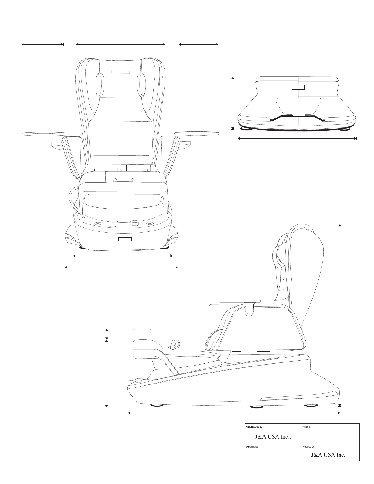
The hot water supply temperature must not exceed 140 . Adjust your hot water accordingly. For hot and cold water supply
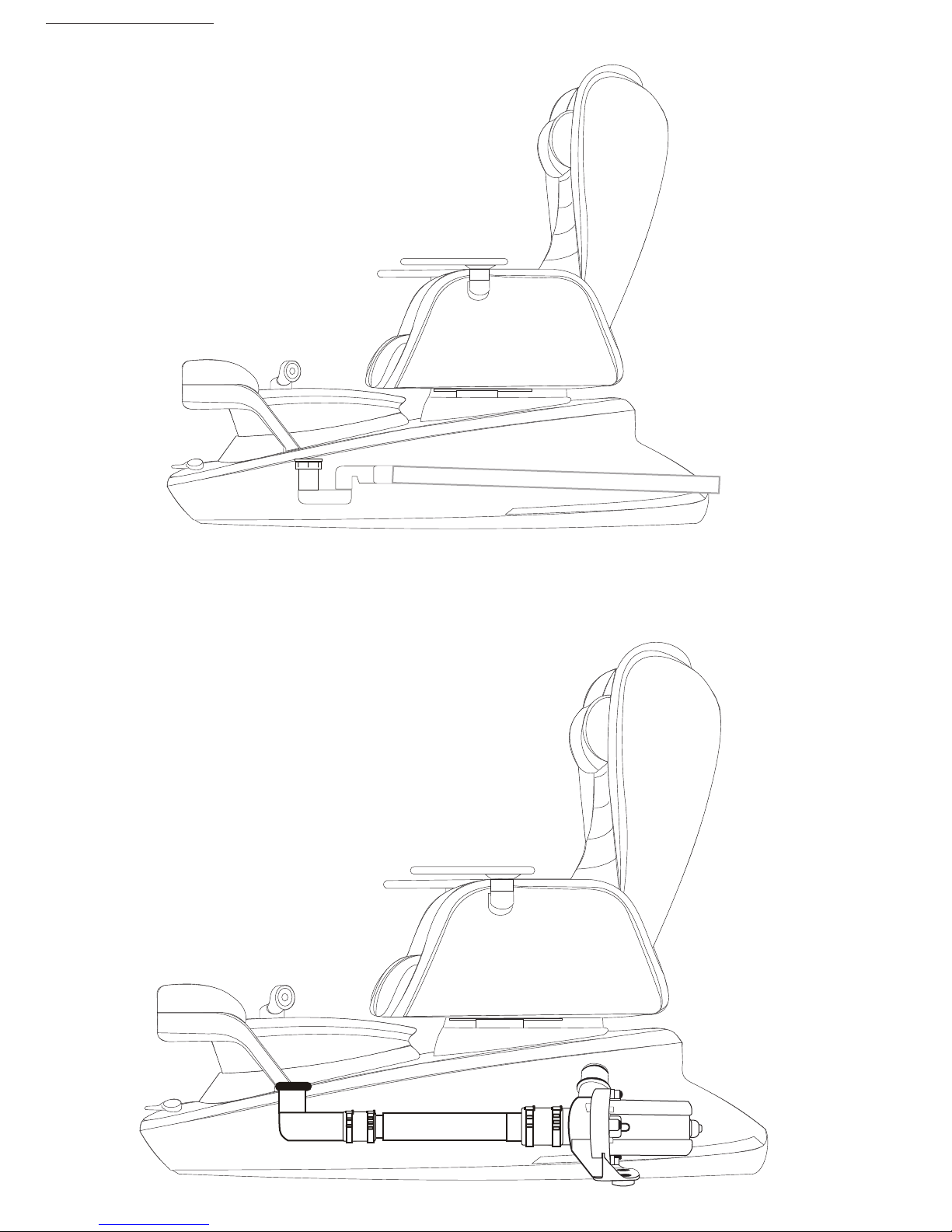
fittings and drain fittings location, see below diagram .Carefully connect the water supply line to the appropriate fittings
located on the rear of the pedicure spa.
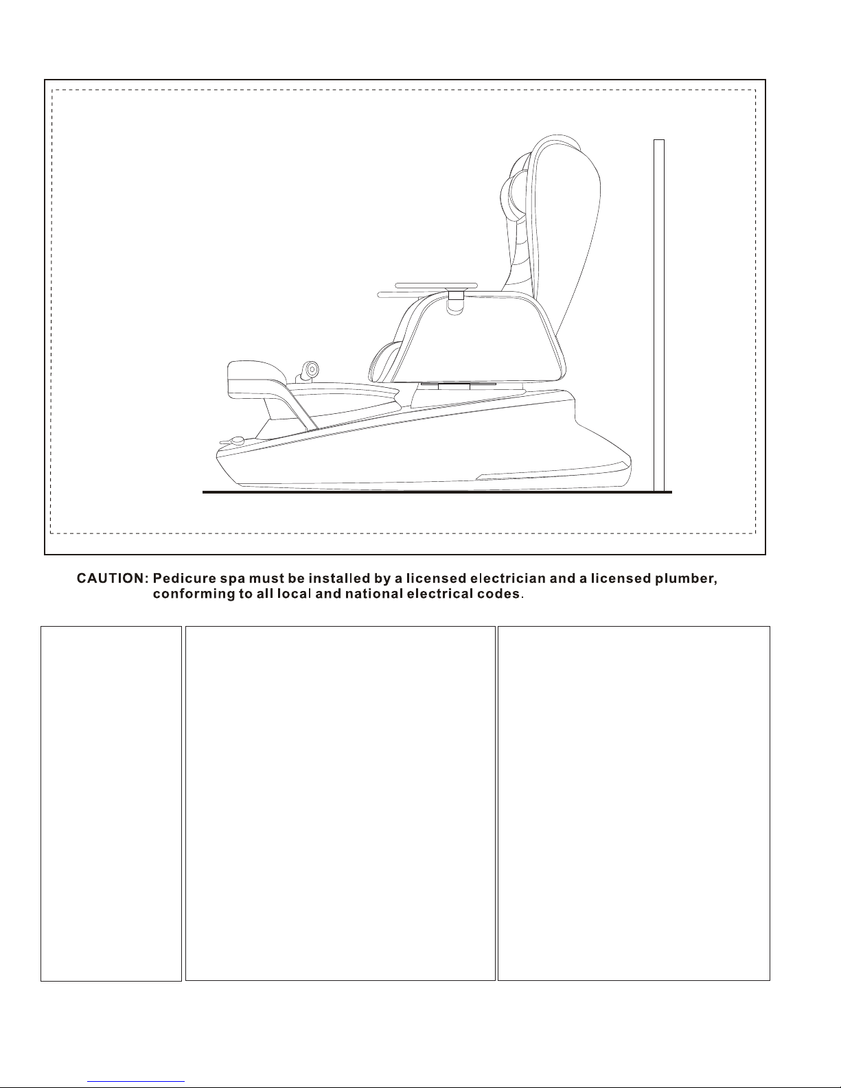
The pedicure spa Drain must meet local plumbing codes. Check valve for Drain (not Provided) Must be installed by a licensed
plumber. Also Pedicure spa must be securely fasten to the floor.
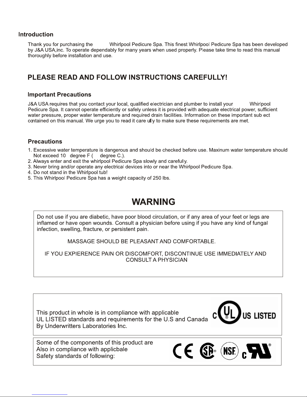
UL LISTED / CE CERTIFIED
Compliance with following Code (s): Uniform Plumbing Code, National Plumbing Code of Canada and international
Plumbing Code. Also, Compliance with following Standard (s): ASME A112.18.3M / A112.18.1M, CSA B125, NSF /
ANSI 61
Drain Facilities
ANSI - American National Institute, ASME - American Society of Mechanical Engineers, CSA - Canadian Standard
Association IAPMO - International Association of Plumbing and Mechanical Officials, UL - Underwriters Laboratory
110V, 60Hz, 15Amp GFCI protected grounded circuit MUST be used to supply power each individual pedicure spa.
And the main circuit breaker MUST be at 25Amp.
Pressure / Temperature
Maximum Pressure: 150 psi (10 bars)
Minimum Pressure: 10 psi (69kPa)
Working Temperature: 33F to 140F constant; intermittent to 180f
(0.6C to 60C sustained; intermittent to 82.2C)
Maximum Recommended Flow: 1.5gpm
Due to Town and / or State requirement/s are varies in building code, if the Town and / or State requires
Vaccum Breaker, As the Plumber MUST provide Vaccum Breaker according to building code
requirement.
Installation Summary
The installation must comply with local, state, and federal building, plumbing and electrical codes, where applicable. A
licensed plumber should complete the plumbing of the pedicure spa.
Note: Failure to comply with federal, state, or local codes and ordinances will result in warranty being nullified and
void.
** Backflow Protection device
All J&A USA products has been compliance with requirements for Whirlpool bath appliances contained in ASME / ANSI
A122.19.7M-1995, CSA C22.2 No. 68-69

IDENTIFICATION
Tray Post
Glass tray
Shower head w/Temperature
indicate - blue/grn/red
2nd remote function
(Slide . Tilting)
Drain Handle (Open & Close)
Air Activate On/Off Button
Single lever Faucet
Tray Post
Glass tray
Remote Control
Glass bowl (Borosilicate)
Arch Footrest post Mech
3 Separated Foot Cushion
Adjustable Center foorest
Glass Bowl Housing
Press button to adjust desire height
Fixed footrest Height
Shower Holder
Pipe- less Whirlpool motor

Specification
Dimension & Weight
Capacity of Tub
Switch
Power Source
Plumbing
Warranty
Lenox - MS Pedicure Spa
Borosilicate Glass bowl
Dedicated 15 Amp. GFCI protected Ground outlet
Magna-Jet Pipelss
Massage System
Hot Water
Cold Water
Drain
Epi - Lenox Pedicure Spa
68”L x 33”W x 55”H 380 Lbs
4.5 U.S Gallons.
On/Off Air Activated Switch
115 Vac. 60Hz. 15 Amp.
120 Vac. 60Hz.
0.5 inches (Fitting Provided)
1.5 inches (See detailed instruction)
One year Parts and labor
Due to continuous improvement on all our products, followings are subject to change without notice: specification, characteristics, packing, information, color and design
All J&A products are equipped with Backflow Protection Device (See detail in Page 26)

LENOX MS
Dimension
68”
12.5” 12.5”
28”
33”
27”
17”
33”
55 1/2”
21”
Note: All dimensions are approximate.
4”

Wall Drain
Drain AConnection
Discharge Pump

15
tilt

61”
30 1/2”
68”
56”
16”
120Vac
GFI Protected
Hot and Cold Water
Hot and Cold Water Inlet : 1/2”
Drain OutLet : 1 1/2” PVC Pipe
Check Valve Shut Off Valves GFCI
Optional - Discharge pump
Top Rear View
Space Requirement
Space Req, for Swivel to Side to Side

½” Brass
Check Valve
Electrical Control Box
(Located left bottom
inside of base)
FU LL TIM E
PART TIM E
PART TIM E
2 Min.Timer
(D.pump)
Light
Transformer
Pipeless Motor
Power Plug
Power Plug
to wall outlet
3/8” clear Tube
from On/Off Switch
for Part time control box
3/8” Clear Tube from on/off for D/P pump
insert into 2 Min. Timer.
Make sure to push in tightly.
PLUMBER MUST BE UTILIZED TO INSTALL
CHECK VALVE
DRAIN OUTLET MUST BE ½”
FOR EFFICIENT DRAINAGE.
(SMALL Rubber Coupling)
Elbow
(LARGE Rubber Coupling)
LARGE Rubber Coupling
3/4” PVC Pipe
HANNING DPO 40 - 020
3/4” Elbow
Rubber Gasket
3/4 PVC Pipe
3/4” PVC Pipe
3/4 SLIP X ½” Male Adaptor
TEE 3/4 X 3/4 X ½
Poly Insert 90 Elb ½”
Clear Tubing 3/4 OD ½”ID
Air Check Valve
L E N O X
SE
Discharge Pump ( Optional):
Up to 4ft @ +/- 39 sec. with 1/2” Connection to main drain

When using electrical equipment, Basic safety precautions must be followed to reduce the risk of fire, electrical shock, and
injury to Persons.
1. Read and follow all instructions before using the equipment.
2. Keep electrical cord out of heavy traffic area. To avoid fire hazard NEVER place electrical cord under the rug, near heat
Generating devices.
3. Always turn power off the equipment before service.
4. Do not drop or insert any object into any openings.
5. Do not operate any equipment with damaged parts.
6. Any other use not recommended by the manufacturer may cause electrical shock or cause injury to person/s.
7. Never use it outdoors
8. Do not attempt to repair or adjust any electrical or mechanical.
1. Hydro dual massage jet stream
2. Magnetic whirlpool jet cover can be remove for quick
cleaning and sanitizing.
3. Built-In electronic sensor for pump control.
4. AC Whirlpool motor (long life)
5. Very low power consumption (27W)
6. Manufactured in USA.
1. Turn off the unit and wait until the motor is fully stops.
2. Hold Hydro whirlpool jet cover firmly and pull to separate from the round magnetic field.
3. Turn hydro whirlpool jet cover to left to open and pull out impeller.
4. Use Anti - Bacterial solution (EPA Registered) to clean all parts.
5. After sanitize all parts, place impeller and close hydro whirlpool jet cover to turn right to lock
6. Hold firmly the whirlpool cover jet and gently place it onto the round magnetic field. Do not release the hydro whirlpool jet cover until
Jet cover is on the round magnetic housing.
Diameter
Hydro-Massage Dual jet Flow
Magnetic
Jet Base
Magnetic
Impeller Magnetic
Whirlpool jet cover
Motor
Round
Magnetic Field (housing)

How to USE Magnetic jet !
Bottom View of
Magnetic Jet Base
WARNING: DO NOT RUN DRY, BASIN MUST FILLED WITH WATER TO LEVEL INDICATOR.
CA UTION: MAGNETIC JET COVER ASSEMBLY MUST ALIGN WITH DISCHARGE PORT
POSITIONED AT 3/9 O’CLOCK.
WHEN READY TO USE, MAKE SURE JET COVER IS POSITIONED AT 3 /9 OCLOCK FOR
PROPER WHIRLPOOL ACTION IN THE BASIN. IF JET COVER IS NOT ALIGN AT 3/9 O’CLOCK,
WATER WILL SPLASH OUTSIDE OF THE BASIN.
PROPER WAY TO USE MAGNETIC JET SYSTEM
1- FILL THE WATER TO WATER LEVEL INDICATOR.
2- HOLD MAGNETIC JET FIRMLY TO BRING CLOSER TO THE ROUND MAGNETIC FILED AND DO NOT
RELEASE
THE MAGNETIC JET PREMATURELY OR THIS WILL CAUSE IMPACTS ON THE JET COVER AND THE
ROUND
MAGNETIC FIELD(HOUSING) SHORTENING THE LIFE EXPECTANCY OF THE JET COVER. WHEN THE JET
COVER NEARS THE ROUND MAGNETIC FIELD, PLACE JET COVER ONTO THE FOUR DIMMPLE AREA
(SEE
DIAGRAM). THE JET COVER MUST ALIGN WITH DISCHARGE PORTS POSITIONED AT 3/9 O’CLOCK.
3- WHEN FINISHED WITH CLIENT, DO NOT REMOVE MAGNETIC JET UNTIL MOTOR IS FULLY STOPPED.
Motor
Round
Magnetic Field (housing)
Magnetic
Jet Base
Magnetic
Impeller Magnetic
Whirlpool jet cover

1. Read and follow all instructions before using the equipment.
2. Keep the cord out of heavy traffic area. To avoid fire hazard NEVER put the cord under the rugs, near heat
generating
devices.
3. Always turn off the equipment before servicing.
4. Do not drop or insert any object into any openings.
5. Do not operate any equipment with a damage parts.
6. Any other use not recommended by the manufacturer may electrical shock or injury to persons.
7. Never use outdoors
When using electrical equipment, basic safety precautions should always be followed to reduce the
risk of fire, electrical shock, and injury to persons, including the following:
Safety Instructions
Cleaning Instruction
1. Turn the unit off and wait until the motor is fully stops.
2. Remove the front jet cover and notice the locking screw in the center
3. Remove the locking center screw (turn counter clockwise) and pull out impeller from housing.
4. Use Anti-Bacterial solution (EPA Registered) to clean all part/s.
5. After sanitization, place impeller onto the motor shaft and fasten with center locking screw ( Turn clockwise)
DURA-JET III Specifications
Model: DURA_JETIII -
Pump: Dual Air Jet Flow
Mounting: Single 3.5” hole Diameter
Auto tighten Mounting screws(4)
J&A USA
120Vac, 0.4 Amp. 60Hz,
1. Dual powerful massage jet-streams
2. Jet assembly can be attached from the pump for
quick cleaning and sanitizing.
3. Built-in electronic sensor for pump control.
4. AC motor (long life)
5. Extremely low power consumption .
6. Manufactured in USA.
DuraJet III Feature
Dura-Jet III
Dura Jet III
Impeller Center
locking mechanism
Dura Jet III
Impeller

Top View
Perspective View
Bottom View
Side View
Rear View
Metal Mesh tray off the floor

LENOX MS REMOTE CONTROL INSTRUCTION
HIGH
MID
LOW
FULL
PARTIAL
SPOT
30
20
10
POSITION
RANGE
MANUAL
MASSGAE
INTENSITY
WHEEL
DN
AUTO
AUTO
KNEAD
COMB
TAP
VIB
KNOCK
MSG
WIDTH
VIBRATION
INTENSITY
UP
DN
UP
INCLINE
Press down to move chair
To desirable angle.
Press down to move chair
To desirable angle.
FORWARD
Press to hold to move
chair to desirable position
Press to hold to move
chair to desirable position
POWER
On / Off
BACKWARD
RECLINE
AUTO
Pre-Programed Automatic
Massage with 2 Selection
POSITION
User’s Height
(HIGH / MID / LOW)
WHEEL
Adjust Massage Wheels
Up and Down to desirable
position.
MANUAL
Press for Manual MODE with
Time Selection of 10~30 Mins.
RANGE
FULL / PARTIAL / SPOT
3 Selections
MSG
Keep Pressing to Massage Wheel
to the intended Massage Width.
COMB
Kneading / Tapping / Knocking
Combinations
TAP
3 Slections of Tapping intensity
SHIATSU
1. Press Manual / Timer to choose
Shiatsu Massage Time Selection
2. Press Massage Range to Select
FULL or PARTIAL Travel
Position.
3. Press Tapping Width to fine
tunecomfort.
KNEADING
3 Selections of Kneading Intensity
KNOCKING
Impulse Tapping Massage.
2 Selections of Knocking Intensity
VIB
2 Selections of Intensity for Seat
vibration Massage.

Massage Mechanism
Back cover Open View
Travel Signal
Sensor
Chair Main Frame
Massage Mechanism Frame
Mechanism Limited frame Bar
Phillip Screws
Massage Mechanism
Frame Fasteners
(3 /ea. side)
Backrest Pivot Fastener
Mechanism Track
Guide Roller
Belt Pulley Kneading Belt
DC Motor (Kneading)
DC Motor (Tapping)
Up and Down Gear Box
DC Motor (Travel)
Belt Pulley
Travel Belt
Tapping Belt
Massage Arm extension
Rod w/ ball extension
Main PCB
Transformer
Bracket For Backrest
Travel Sensor
Main Remote Control
2nd Slide / recline remote
Control slot
PCB Fuse
Vibration(Grn/Yel)
Red (Recliner)
White (Slider)
D/C Motors
Board Holders
Power
PCB Case
Wire connectivity to Main PCB

Placing Backrest in Correct position
1
Pull latch upward to release
Red
Black
White
Green
Color code Receptacle Connection
location: Under Seat Cushion
Red : Tilting (Up & Down)
White : Slide ( forward and back)
Green: Seat Vibration
Black : 2nd remote
Top View (Seat Frame)
Table of contents
Popular Hot Tub manuals by other brands

Alisun
Alisun SunVision V Series User manual software

JNJ SPAS
JNJ SPAS SPA-8098 operating instructions

Kohler
Kohler 1199250-2-A Installation and care guide

Kohler
Kohler K-1152-L Roughing-In Guide

Bestway
Bestway Lay-Z-Spa Hawaii HydroJet Pro manual

Jacuzzi
Jacuzzi DESIGNER BATH SERIES Installation & operation instructions

Maya Group
Maya Group Orbeez Instruction guide

American Standard
American Standard Cadet Elite 2774EC Features & dimensions

Tylo
Tylo Tylette Duo Installation and operating instructions with checklist

Stoked
Stoked Hot tub user manual

Aquatic
Aquatic LUXEAIR 30 ai30lux6036 Specification sheet

Hydropool
Hydropool Serenity 2009 user manual