Lesco Commercialplus Green Monster 706725 User manual

Walk-Behind
Blower
PARTS LIST AND
OPERATOR’S INSTRUCTIONS
Model #: 706725 8hp Kawasaki
706925 8hp Intek
706927 11.5hp Kawasaki
706929 11hp Vanguard
Starting Date: 8/2002-

2
Customer Name
Customer Address
City
State Zip Code
Engine Make
Model Number
Serial Number
Spec. Number
ENGINE INFORMATION
Factory Model Number
Serial Number
Product Information
You will find below a product information form. Please take a moment and fill in
the spaces provided below with the information from your unit. Recording your
product information will help you as a customer save time when ordering parts or
servicing your unit. It will also help Lesco Technical Support provide you with fast
and timely service.
Note: Please read this entire Operator’s and Instructions Manual and
Engine Owners Manual before placing this unit into service.
Patent Pending

3
INTRODUCTION
CAUTION:
The Walk-Behind Blower should only be operated and maintained by thoroughly trained individuals. The machine
can cause serious injury to anyone who misuses it or does not understand its operation. All operator’s and
maintenance personnel are urged to read this entire manual for their personal safety.
Note: Safety goggles and long pants should be worn when operating or maintaining this machine. Do not
operate machine for more than 2 hours without hearing protection.
This manual presents the safety, operating instructions and parts breakdowns to keep your Walk-Behind Blower at
peak efficiency. If properly operated and maintained, your Walk-Behind Blower will give dependable service.
SAFETY PRECAUTIONS
1. Read this manual thoroughly before operating or
maintaining the blower.
2. Always wear safety glasses and long pants when
operating or maintaining this machine. Do not wear
loose-fitting clothing.
3. Always disconnect the spark plug wire before
adjusting or maintaining this machine.
4. When operating, keep your hands and feet away
from the side discharge and your hands and
clothing away from the fan quard.
5. Do not remove any shields, guards or decals. If a
shield, guard or decal is damaged or does not
function, repair or replace it before operating the
blower.
6. Altering this machine in any way may cause injury
to the operator or bystanders.
7. Keep people and pets away from the blower when
in use.
8. When operating, never direct the air stream at walls
or vertical objects which can deflect debris back at
you.
9. When operating, never direct the air stream at
painted objects.
10. If a breakdown occurs, shut off the engine
immediately, disconnect the spark plug wire and do
not connect until repairs have been made.
11. Never run the engine indoors without adequate
ventilation. Exhaust fumes are deadly.
12. To avoid serious burns, do not touch the engine,
exhaust pipe or muffler while the engine is running
or until it has cooled after it has been shut off.
13. Stop the engine and allow it to cool before refilling
the gas tank.
14. Gasoline is extremely dangerous and flammable.
Do not permit open flames or sparks near the
engine at any time.
15. Keep the blower and especially the engine air
screen and cooling fins clean and free of grease,
grass and leaves to reduce the chance of fire and
to permit proper cooling.
PREPARATION
1. Open the packing. Make certain the engine’s
spark plug wire is disconnected.
2. Assemble the upper and lower handles to the
engine plate as shown in figure 1.
3. Check and tighten all nuts and bolts as necessary.
4. Check the air pressure in the tires. It should be 18-
22 psi. CAUTION: Do not overinflate.
5. Fill the engine with oil. The oil should be up to but
not over the “Full” mark on the dipstick. Above 32°
F. use SAE 30 oil. Below 32° F. use SAE 5W20 or
SAE 5W30.
6. Fill the gas tank. Use fresh, clean, regular,
unleaded gasoline. Leave 1/4 inch at the top of the
tank for expansion.

4
OPERATING INSTRUCTIONS
Prior to Each Day’s Use:
1. Disconect the engine’s spark plug wire.
2. Clean the cooling air intake screen and cooling fins.
(See engine manual).
3. Clean the air filter paper element by gently tapping on
the flat side. Do not wash or use pressurized air. (See
engine manual).
4. Position the blower on a level surface and check the
engine oil level.
5. Fill the gas tank.
6. Check and tighten all nuts and bolts as necessary.
To Start the Blower:
1. Connect the engine’s spark plug wire.
2. Open the fuel shutoff valve.
3. Move the engine switch to “ON”. Move the choke control
on the engine to “CHOKE”. Move the throttle control to
halfway between “SLOW” and “FAST”.
4. Grasp the starter grip and pull slowly until the starter
engages and then pull the cord rapidly to overcome
compression, prevent kickback and start the engine.
Allow the cord to recoil slowly. Repeat if necessary.
5. Once the engine starts, close the choke control and
when the engine has warmed up, adjust the throttle to
produce the amount of sweeping power required.
6. Move to the point where you want to begin sweeping.
The sweeping action is most effective if, as you move
forward, you keep the front of the machine down and
close to the work surface to blow out holes and
crevices.
7. To shut off the machine, move the engine throttle
control to the “SLOW” position, shut off the engine
switch and after the engine has stopped, disconnect the
engine’s spark plug wire and shut the fuel shutoff valve.
8. After use, thoroughly clean the machine especially the
engine’s air intake screen and cooling fins.
NOZZLE OPERATING INSTRUCTIONS
The blower is equipped with a dual purpose nozzle (air
outlet):
1. When the nozzle is oriented in
this position (see Fig. 1 and
illustration 1) leaves and debris
on ground level are propelled to
a distance proportion to engine
speed. Leaves at the top of the
pile have a tendacy to circle
back from eddy currents that are
created by the blower air flow.
2. When the nozzle is oriented as
shown in Figure 2 and
illustration 2 - The air flow will
naturally “knock down” leaves
and prevent them from circling
back from eddy currents.
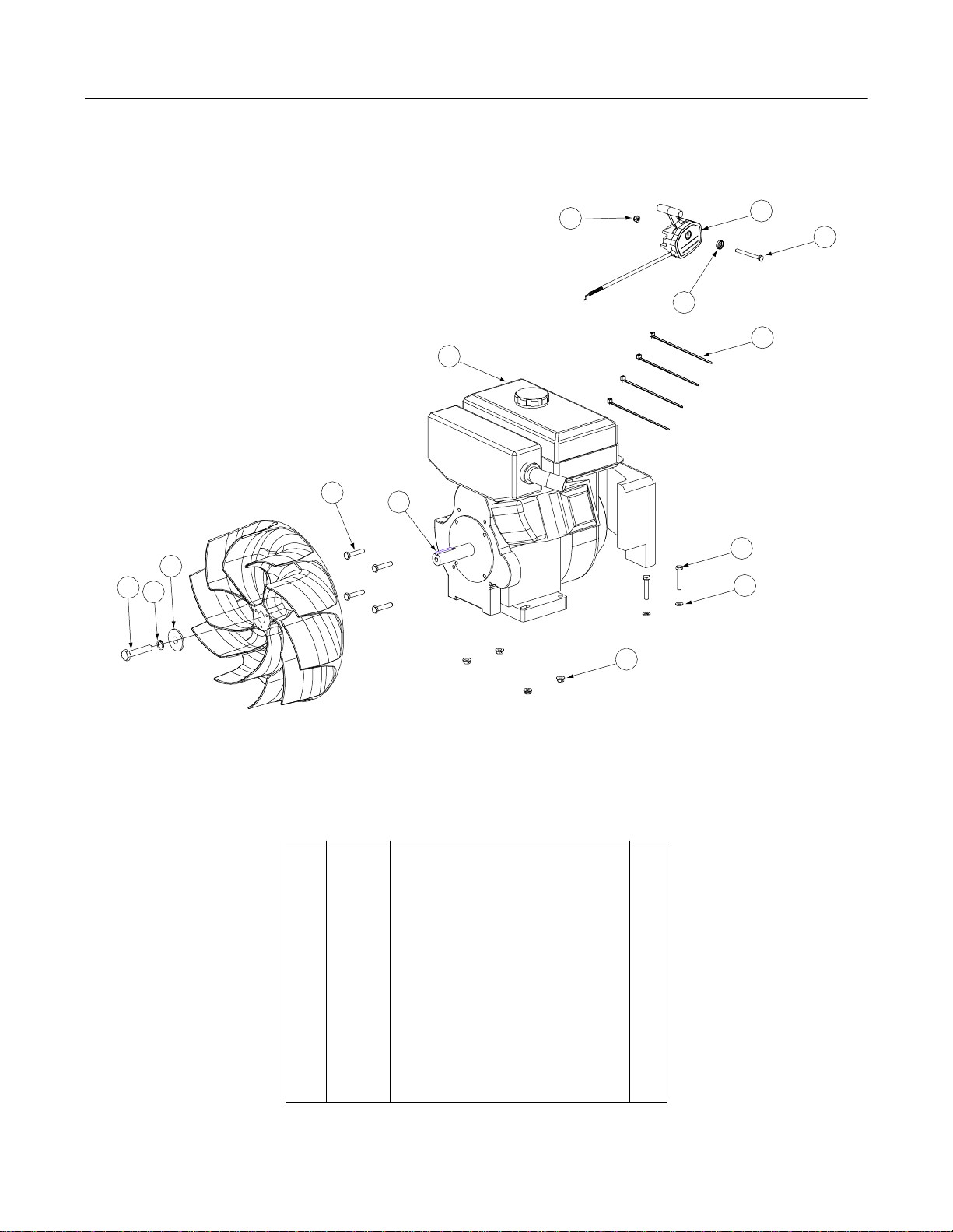
To change position of nozzle:
1. Unscrew and remove thumb
knob (060043) from u-bolt (706397).
2. Pull out u-bolt.
3. Pull off nozzle (706887), rotate 180° and replace back
onto unit.
4. Replace ubolt and thumb knob.
To change position of handle:
1. Remove hardware connecting upper handle (706907) to
lower handles (706908).
2. Relocate upper handle — either lower of higher to next
set of mounting holes.
3. Replace hardware and tighten.
Fig.1
Fig.2
Figure 1 nozzle orientation
Illustration 1
Figure 2 nozzle orientation
Illustration 2
ENGINE MAINTENANCE
Every 25 Hours:
Service the foam air precleaner. Wash in soap and
water, rinse and dry. Re-oil with clean engine oil.
Change the oil. Change the oil more frequently under
dusty conditions. See the oil specifications above.
Grease wheels with pneumatic tires. Use No. 005039
General Purpose Gun Grease.
Every 50 Hours:
Service the fuel filter.
Every 100 Hours:
Replace the air filter paper element. Replace the
paper element more frequently under dusty conditions.
Troubleshoot:
If severe vibration occurs, shutoff unit. Check housing
and impeller and clear any debris.

5
Blower Handle Assembly - Figure 1
Ref.
No. Part No. Description Qty.
1 012169 Flat Washer, 5/16 8
2 013198 Hex Cap Screw, 5/16-18 x 2 4
3 083192 Idler Washer 4
4 700635 Hex Flange Lock Nut, 5/16-18 4
5 702766 Hex Flange Lock Nut, 1/4-20 4
6 706907 Upper Handle 1
7 706908 Lower Handle 2
8 706747 Cap Screw, 1.25 2
9 706888 Foam Grip 2
10 707234 Rubber Grommet, 1.06 x .365ID x.25LG 8
11 707550 Handle Brace 2
12 707237 Shoulder Bolt, 5/16 x 2.00 4
Optional Kit
707576 Kit, Blower Handle w/ Grips (Includes)
9 706888 Foam Grip 2
6 706907 Upper Handle 1
Optional Kit
707538 Kit, Blower Handle (Includes)
1 012169 Flat Washer, 5/16 2
2 013198 Hex Cap Screw, 5/16-18 x 2 2
4 700635 Hex Flange Lock Nut, 5/16-18 2
6 706907 Upper Handle 1
9 706888 Foam Grip 2
11 707550 Handle Brace 2
6
2
8
4
11
12
1
7
7
10
10
3
1
9
5
GD: 01006723-P02

6
8hp Kawasaki Engine Assembly - Figure 2
Ref.
No. Part No. Description Qty.
1 012382 Hex Cap Screw, 5/16-18, 1-1/2 4
2 012169 Flat Washer, 5/16 4
3 012470 Cable Tie, 3/16 x .05 x 7.4 4
4-- -- --
5 700446 Hex Lock Nut, 1/4-20 1
6 700635 Hex Flange Lock Nut, 5/16-18 4
7 700898 Hex Cap Screw, 1/4-20, 2.50 1
8-- -- --
9 701002 8HP Kawasaki Engine 1
10 706585 Hex Cap Screw, M8-1.25 x 40 4
11 707145 Throttle 1
12 700961 Wave Washer 1
13 700905 M10-1.5 x 50mm Capscrew 1
14 705314 Flat Washer 1
15 012062 M10 Lock Washer 1
16 707533 1/4 x 1/4 x 2.75 Key 1
5
12
10 16
14
13 15
9
7
1
2
6
3
11
GD: 01006722-P08

7
8hp B&S Intek Pro Engine Assembly - Figure 3
Ref.
No. Part No. Description Qty.
1 012169 Flat Washer, 5/16 4
2 012470 Cable Tie, 3/16 x .05 x 7.4 4
3-- -- --
4-- -- --
5 700446 Hex Lock Nut, 1/4-20 1
6 700635 Hex Flange Lock Nut, 5/16-18 4
7 700898 Hex Cap Screw, 1/4-20, 2.50 1
8 706922 8HP Briggs & Straton Intek Pro Engine 1
9 707128 Engine Spacer 2
10 707122 Hex Cap Screw, 5/16-18 x 2.5 4
11 707248 Hex Cap Screw, 5/16-24 x 1.50 4
12 707145 Throttle 1
13 700961 Wave Washer 1
14 701082 7/16-20 x 2.00 Capscrew 1
15 705314 Flat Washer 1
16 700389 7/16 Lock Washer 1
17 707533 1/4 x 1/4 x 2.75 Key 1
13
5
12
7
2
10
6
11
6
11
17
9
1
8
15
14 16
GD: 01007106-P06

8
11hp B&S Vanguard Engine Assembly - Figure 4
Ref.
No. Part No. Description Qty.
1 006129 Hex Cap Screw, 5/16-18, 1-3/4 4
2 012169 Flat Washer, 5/16 4
3 012470 Cable Tie, 3/16 x .05 x 7.4 4
4-- -- --
5 700446 Hex Lock Nut, 1/4-20 1
6 700635 Hex Flange Lock Nut, 5/16-18 4
7 700898 Hex Cap Screw, 1/4-20, 2.50 1
8-- -- --
9 706923 11HP B&S Vanguard Engine 1
10 707248 Hex Cap Screw, 5/16-24 x 1.50 4
11 705303 Throttle 1
12 700961 Wave Washer 1
13 707124 Throttle Label 1
14 701082 7/16-20 x 2.00 Capscrew 1
15 705314 Flat Washer 1
16 700389 7/16 Lock Washer 1
17 707533 1/4 1/4 x 2.75 Key 1
7
9
10 17
12
5
3
1
2
6
11
13
15
14 16
GD: 01007107-P05

9
11.5hp Kawasaki Engine Assembly - Figure 5
Ref.
No. Part No. Description Qty.
1 006129 Hex Cap Screw, 5/16-18, 1-3/4 4
2 012169 Flat Washer, 5/16 4
3 012470 Cable Tie, 3/16 x .05 x 7.4 4
4-- -- --
5 700446 Hex Lock Nut, 1/4-20 1
6 700635 Hex Flange Lock Nut, 5/16-18 4
7 700898 Hex Cap Screw, 1/4-20, 2.50 1
8-- -- --
9 704877 11.5HP Kawasaki Engine 1
10 706585 Hex Cap Screw, M8-1.25 x 40 4
11 707145 Throttle 1
12 700961 Wave Washer 1
13 700905 M10-1.5 x 50mm Capscrew 1
14 705314 Flat Washer 1
15 012062 M10 Lock Washer 1
16 707533 1/4 x 1/4 x 2.75 Key 1
7
9
12
11
5
3
10 16
1
2
6
14
13 15
GD: 01007108-P04

10
Blower Housing Assembly - Figure 6
Ref.
No. Part No. Description Qty.
1-- -- --
2 030268 Decal, “Danger Fan” 1
3 704125 Overlayment Label 1
4 060043 Control Rate Knob 1
5 090006 Decal, Made In America 1
6 030468 Label, Safety Procedures 1
7 702766 Hex Flange Lock Nut, 1/4-20 6
8 708278 Front Housing Ring Plate 1
9 706904 Housing Assembly 1
10 706906 Wire Guard 1
11 706397 Finger Guard 1
12 706629 Intake Housing 1
13 706887 Nozzle 1
14 707007 Decal, Lesco Commercial Plus 1
15 706896 Decal, Green Monster Logo 1
16 708290 17" Cast Impeller Assembly 1
17 707182 Decal, Blower Housing Rectangular 1
18 707181 Decal, Blower Housing Curved 1
19 707332 Decal, Nozzle Lesco 1
15
4
17
18
7
5
3
6
14
10
12
8
7
2
19
11
13
9
16
GD: 01006726-P08

11
Blower Frame Assembly - Figure 7
Ref.
No. Part No. Description Qty.
1 008679 Wheel, 410/350 x 4 - 2Ply 3
2 012675 Hex Cap Screw, 1/2-13 x 5-1/2 1
3 023649 Spacer, .790 ID x .347 Lg 2
4 023796 Flat Washer, .750 x 1.50 x .120 4
5 700635 Hex Flange Lock Nut, 5/16-18 4
6 700641 Carriage Bolt, 5/16-18 x 1 4
7 700749 Spacer 1
8 701166 Hex Lock Nut, 1/2-13 1
9 701777 Hex Lock Nut, 3/4-10 2
10 706909 Engine Frame Assembly 1
11 706910 Front Wheel Support 1
1
56
93
6
81
3
9
42
11
7
10
Note 1: Use Part No. 050539 General Purpose Gun Grease GD: 01006724-P02

Equipment Two-Year Limited Warranty
1. What Is Covered By This Warranty. LESCO, Inc. warrants, to the original purchaser only, that the Equipment that is the subject of this sale (a)
conforms to LESCO’s published specifications, and (b) is free from defects under normal service, for a two-year period from the original date of delivery.
This warranty does not include damage to the Equipment resulting from occurrences set forth hereinafter in (2). If the purchaser discovers within this period
a failure of the Equipment to conform to specifications or a defect in material or workmanship, they must promptly notify LESCO in writing of such claim.
Any claims under this warranty must be received in writing by LESCO within 25 months from the date of original delivery. Within a reasonable time after
such notification, LESCO will replace any defective component of the Equipment or part thereof. LESCO will provide the components or parts at LESCO’s
expense. Labor is to be performed by the original purchaser. (LESCO will provide purchaser a labor allowance at LESCO’s current flat rate schedule.)
LESCO will make the final determination as to the amount of hours to be reimbursed to the purchaser for labor. All defective parts shall be returned to
LESCO if requested. These remedies are the original purchaser’s exclusive remedies for breach of warranty.
2. What Is Not Covered By This Warranty. LESCO does not warrant (a) any product, components or parts not manufactured by LESCO; (b) defects
caused by failure to provide a suitable installation environment for the Equipment; (c) damage caused by use of the Equipment for purposes other than those
for which it was designed; (d) damage caused by accident or disasters such as fire, flood, wind and lightning; (e) damage caused by unauthorized
attachments or modification; or (f) any other abuse or misuse of the Equipment.
3. EXCLUSIVE WARRANTY. THE FOREGOING WARRANTY IS EXCLUSIVE AND IN LIEU OF ALL OTHER WARRANTIES OR
REMEDIES, WHETHER WRITTEN, ORAL OR IMPLIED. ANY AND ALL IMPLIED WARRANTIES OF MERCHANTABILITY, FITNESS FOR A
PARTICULAR PURPOSE, COURSE OF DEALING OR USAGE OF TRADE ARE HEREBY EXPRESSLY DISCLAIMED AND EXCLUDED.
4. LIMITATION OF REMEDIES. UNDER NO CIRCUMSTANCES, EXCEPT TO THE EXTENT PROHIBITED BY APPLICABLE LAW,
SHALL LESCO BE LIABLE FOR ANY LOSS OR DAMAGE, DIRECT OR INDIRECT, SPECIAL, INCIDENTAL OR CONSEQUENTIAL ARISING
OUT OF THE USE OF OR INABILITY TO USE THIS EQUIPMENT INCLUDING BUT NOT LIMITED TO ANY CLAIM FOR LOSS OF PROFITS,
LOSS OF SAVINGS OR REVENUE, LOSS OF USE OF THE EQUIPMENT OR ANY ASSOCIATED EQUIPMENT, FACILITIES OR SERVICE,
DOWNTIME, THE CLAIMS OR COSTS OF THIRD PARTIES INCLUDING CUSTOMERS, AND INJURY TO PROPERTY.
Some states do not allow limitations on how long an implied warranty lasts or the exclusion or limitation of incidental or consequential damages, so the
above limitations or exclusion may not apply to you. This warranty gives you specific legal rights, and you may also have other rights which vary from state
to state.
5. Time Limit For Claims. Any claim for breach of warranty or claims under this warranty must be received by LESCO within 25 months following
delivery of the equipment.
6. No Other Warranties. Unless modified in writing signed by both parties, this agreement is understood to be the complete and exclusive agreement
between the parties, superceding all prior agreements, oral or written, and all other communications between the parties relating to the subject matter of this
agreement. No employee or representative of LESCO or any other party is authorized to make any other Warranty or to assume any other liability in
connection with the sale of its Equipment.
7. Future Changes. LESCO reserves the right to reserve, change or modify the construction and design of its Equipment or any component part or
parts thereof without incurring the obligations to make such changes or modifications in present equipment.
8. Allocation Of Risks. This agreement allocates the risks of equipment failure between LESCO and the original purchaser. This allocation is
recognized by both parties and is reflected in the price of the goods. THE PURCHASER ACKNOWLEDGES THAT IT HAS READ THIS AGREEMENT,
UNDERSTANDS IT, AND IS BOUND BY ITS TERMS.
9. How To Contact LESCO. If during the warranty period, the Green Monster Blower does not function properly due to defect, simply contact the
LESCO Service Department:
LESCO, Inc. (440) 783-9250 Cleveland
Technical Service Department (800) 321-5325 Toll Free
P.O. Box 368000-9998
Strongsville, OH 44136-9998
HOW TO ORDER PARTS
Contact your LESCO Salesperson, OR phone us (use the numbers above), OR write us (use the address above). We will need the following information:
1. Your account number if available.
2. Your name and address and the address where you want the parts to be shipped.
3. The Model/Serial No. of the equipment.
4. The LESCO Part No. and the quantity desired. (Please do not use reference numbers.)
NOTE: Inspect all shipments on receipt for damage or missing parts. File a claim with the carrier before accepting a damaged shipment.
We reserve the right to change designs, specifications and equipment at any time without notice and without incurring any obligations.
LESCO, Inc., 15885 Sprague Road, Strongsville, Ohio 44136-1799
Toll Free (800) 321-5325 • In the Cleveland Area (440) 783-9250
Form No. 708402 Rev. 03-0AA 4/15/2003 © Copyright 2003 - LESCO, Inc. LESCO is a registered trademark of LESCO Technologies, LLC
LESCO Commercial Plus and Green Monster are trademarks of LESCO Technologies, LLC
Intek Pro and Vanguard are registered trademarks of Briggs and Stratton Corporation
This manual suits for next models
3
Table of contents
Popular Blower manuals by other brands

STEWART-AMOS
STEWART-AMOS Starfire S-5t Safety, operation & maintenance manual

Husqvarna
Husqvarna 356BTX Series Workshop manual

Stihl
Stihl BR 200 instruction manual

Weed Eater
Weed Eater BV200 instruction manual

EINHELL
EINHELL GE-CF 18/2200 Li Original operating instructions

YATO
YATO YT-85800 Original instructions