LESLIE 7467 CONSOLE CONNECTOR KIT INSTALLATION INSTRUCTIONS
FOR USE WITH: WURLITZER Model 4700
LESLIE 212S Speaker
MULTIPLE SPEAKER INSTALLATION: For complete information, see the service manual
of the specific model LESLIE Speaker to be added.
CONTENTS OF KIT:
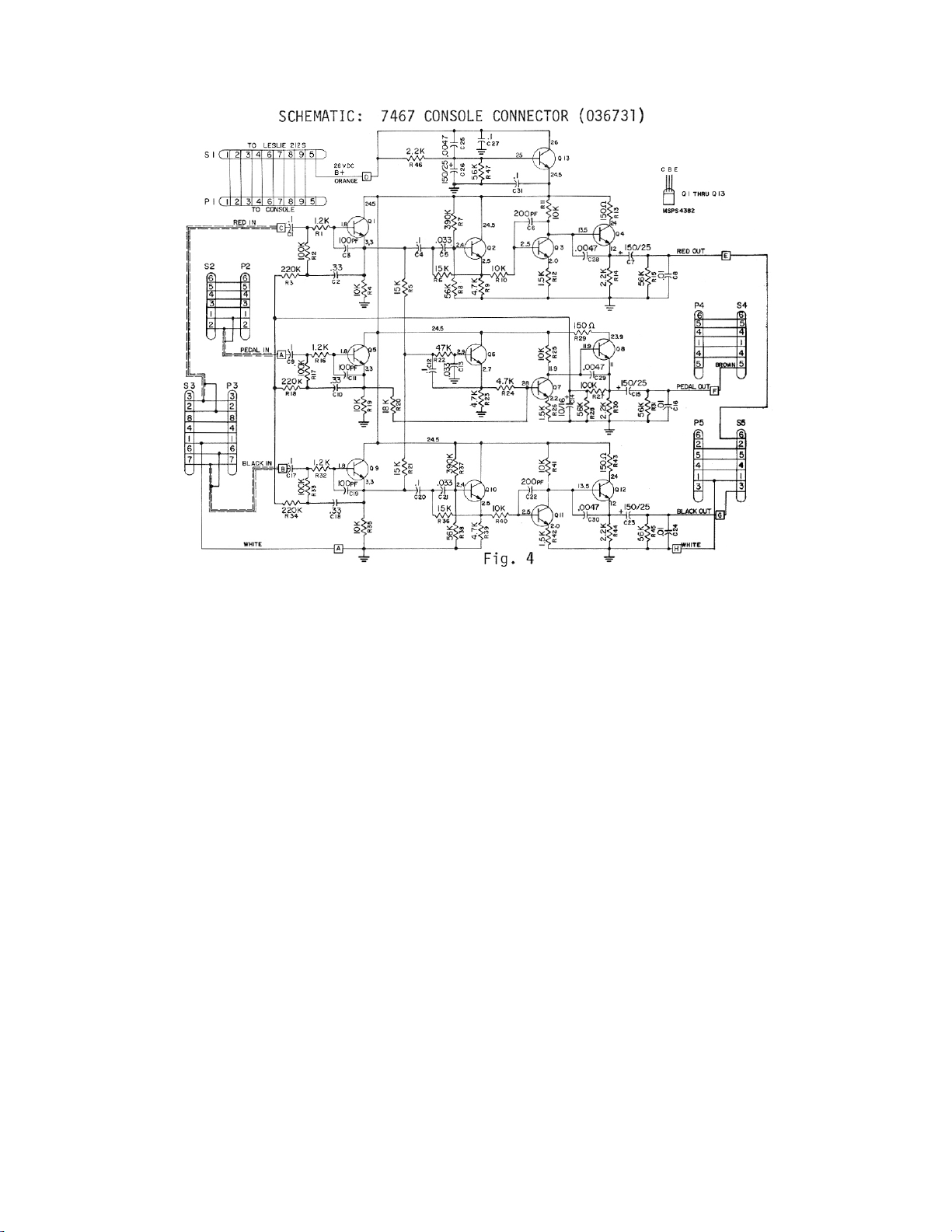
1 Console Connector
036731
1 9 Conductor Cable
021600
1 Instructions
036988
1 Oiler
053025
2 Wood Screws 8 x 1/2
029132
WARNING: Do NOT connect the Leslie 212S Speaker to the Wur1itzer model 4700
without first installing a Wurlitzer Left Hand Cheek Block Kit available from the
Wurlitzer Service Department: SEVERE DAMAGE MAY RESULT. Electro Music will not be
responsible for any damage due to installation without this kit.
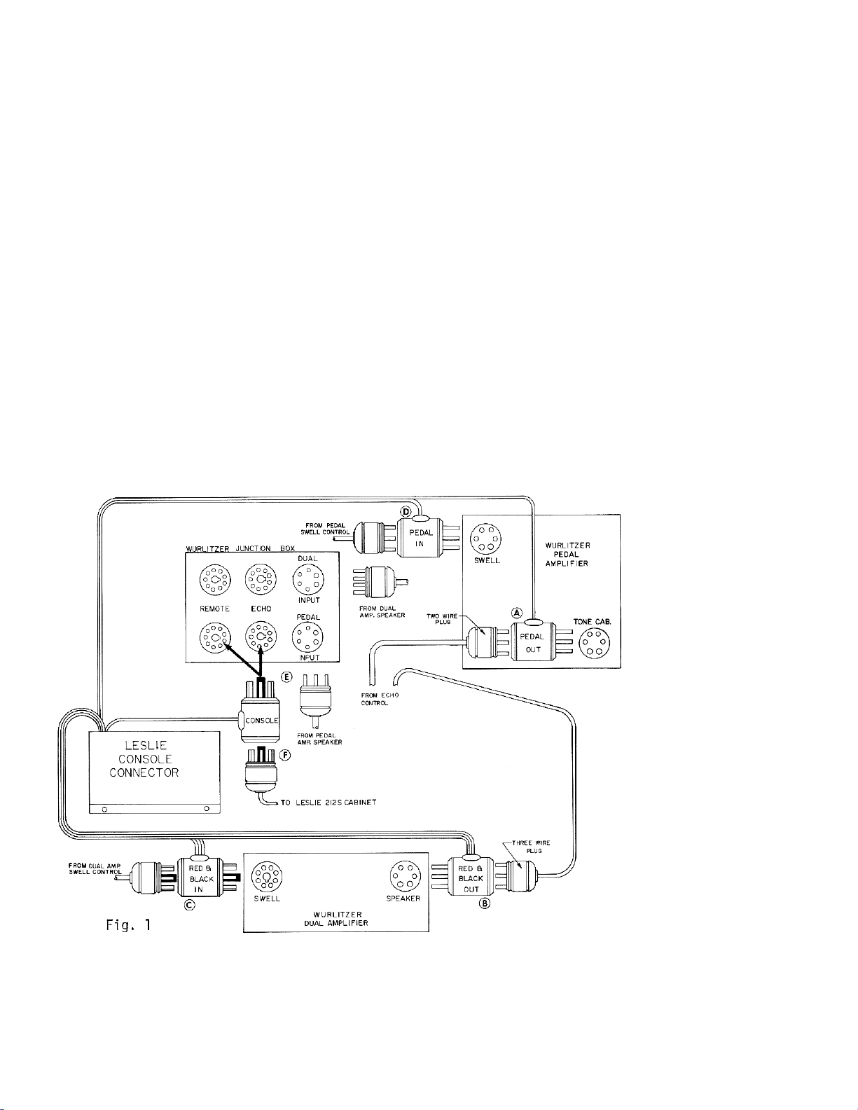
TO INSTALL THE CONSOLE CONNECTOR KIT:
1. Disconnect Wurlitzer AC power plug and back cover.
2. Mount console connector chassis inside the Wurlitzer. Interceptor cables should
reach the Wurlitzer junction box, dual amp, and pedal amp.
3. Now make certain a Wurlitzer junction box for Leslie 212S installations is mounted
within the Wurlitzer. Two and three wire cables from the Wurlitzer echo controls
should be connected to the pedal and dual amplifiers, respectively. Also make
certain cables from the Wurlitzer dual and pedal speakers are connected to the
"DUAL INPUT" and "PEDAL INPUT" sockets on the Wurlitzer junction box.
4. Disconnect two wire echo control plug from the "TONE CAB" socket on the pedal
amp and insert it into the "PEDAL OUT" console connector interceptor. Then plug
this interceptor lnto the "TONE CAB" socket on the Wurlitzer pedal amp. (See "A"
on Fig. 1)
5. Disconnect three wire echo control plug from the "SPEAKER" socket on the dual
amp and insert it into the "RED & BLACK OUT" console connector interceptor.
Then plug this interceptor into the "SPEAKER" socket on the Wurlitzer dual amp.
(See "B" on Fig. 1)
6. Disconnect plug from the "SWELL" socket on the Wurlitzer dual amplifier. Insert it
into the "RED & BLACK IN" console connector interceptor. (See "C" on Fig. 1)
Page 1 of 6