Leuze electronic LSIS 4xxi4
Figures and tables
Figure 3.1: Application example: presence monitoring ......................................................................... 11
Figure 3.2: Application example: completeness monitoring.................................................................. 11
Figure 3.3: Application example: orientation detection.......................................................................... 12
Figure 3.4: Application example: code verification................................................................................ 12
Figure 3.5: Application example: dot-peened Data Matrix code............................................................ 13
Figure 3.6: Application example: label positioning and label identification............................................ 13
Figure 3.7: Application example - measurement of radii and roundness .............................................. 14
Figure 3.8: Detecting objects with webConfig ....................................................................................... 15
Figure 3.9: Standard device construction.............................................................................................. 16
Figure 3.10: Device construction variants for C-mount interchangeable lens......................................... 16
Figure 3.11: Stand-alone connection ...................................................................................................... 17
Figure 4.1: Device name plate LSIS 4xxi.............................................................................................. 18
Figure 4.2: Fastening options using M4 threaded holes ....................................................................... 19
Figure 4.3: BT 56 mounting device ....................................................................................................... 20
Figure 4.4: Mounting examples of LSIS 4xxiwith BT 56 ...................................................................... 21
Figure 4.5: BT 59 mounting device ....................................................................................................... 21
Figure 4.6: Camera distance / image field - standard devices .............................................................. 23
Figure 4.7: Camera distance / image field - device models for C-mount interchangeable lenses ........24
Figure 4.8: Lens replacement for C-mount devices .............................................................................. 25
Figure 4.9: Optional polarization filter for standard devices .................................................................. 26
Figure 4.10: Filter replacement for C-mount devices ..............................................................................27
Figure 5.1: Location of the electrical connections ................................................................................. 29
Figure 5.2: Connections of the LSIS 4x2i............................................................................................. 31
Table 5.1: Pin assignments - PWR ...................................................................................................... 32
Figure 5.3: Connection diagram of IO1 through IO8 configured as switching inputs ............................ 33
Figure 5.4: Connection diagram of IO1 through IO8 configured as switching outputs.......................... 33
Table 5.2: Pin assignment BUS OUT................................................................................................... 34
Figure 5.5: RS 232 pin assignments ..................................................................................................... 34
Table 5.3: SERVICE pin assignments ................................................................................................. 35
Figure 5.6: Cable assignments - SERVICE on RJ-45........................................................................... 35
Table 6.1: Address assignment in the Ethernet ................................................................................... 37
Figure 6.1: Connecting the LSIS 4xxito the PC ................................................................................... 38
Figure 6.2: webConfig start page .......................................................................................................... 39
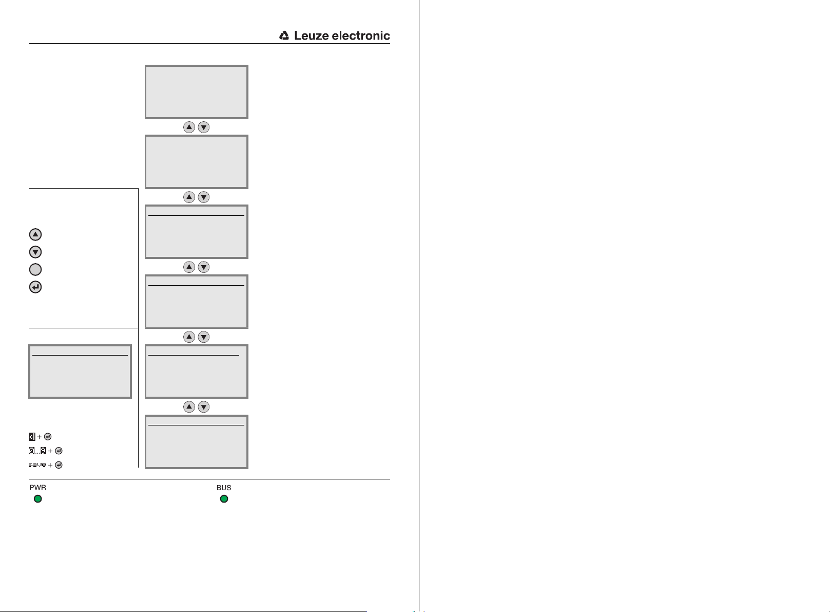
Figure 7.1: Structure of the control panel.............................................................................................. 41
Table 7.1: Parameter handling submenu............................................................................................. 46
Table 7.2: Program selection submenu ............................................................................................... 46
Table 7.3: Ethernet submenu............................................................................................................... 47
Table 8.1: General causes of errors..................................................................................................... 51
Table 9.1: Type overview LSIS 4xxi- standard devices ...................................................................... 52
Table 9.2: Type overview LSIS 4xxi- C-mount devices ...................................................................... 53
Table 9.3: Type overview LSIS 4xxi- C-mount lenses ........................................................................ 53
Table 9.4: Accessories for the LSIS 4xxi............................................................................................. 53
Table 9.5: Pin assignments KD S-M12-8A-P1-… ................................................................................ 54
Table 9.6: PWR cables for the LSIS 4xxi............................................................................................. 54
Table 9.7: Pin assignments KS S-M12-8A-P1-… ................................................................................ 55
Table 9.8: BUS OUT cables for the LSIS 4xxi..................................................................................... 55
Table 9.9: Ethernet connection cables featuring M12 plug/open cable end........................................ 56