Leviton Energy Monitoring Hub A8812 Owner's manual

Energy Monitoring Hub –Data Acquisition Server
Installation and Operation Manual
Model A8812
Shop for Power Metering products online at: 1.800.561.8187
www.PowerMeterStore.ca

Warranty Information
LIMITED FIVE YEAR WARRANTY AND EXCLUSIONS
Leviton warrants to the original consumer purchaser and not for the benefit of anyone else that this product at the time of its
sale by Leviton is free of defects in materials and workmanship under normal and proper use for five years from the
purchase date. This Warranty is limited to repair or replacement of defective equipment returned Freight Pre-Paid to Leviton
Manufacturing at 20497 SW Teton Ave., Tualatin, Oregon 97062, USA. User shall call 1-800-959-6004 and request a return
authorization number to mark on the outside of the returning carton, to assure that the returned material will be properly
received at Leviton.
All equipment shipped back to Leviton must be carefully and properly packed to avoid shipping damage. Replacements or
repaired equipment will be returned to sender freight prepaid, F.O.B. factory. Leviton is not responsible for removing or
replacing equipment on the job site, and will not honor charges for such work. Leviton will not be responsible for any loss
of use time or subsequent damages should any of the equipment fail during the warranty period, but agree only to repair or
replace defective equipment returned to its plant in Tualatin, Oregon.
This Warranty is void on any product that has been improperly installed, overloaded, short circuited, abused, or altered in
any manner. Neither the seller nor Leviton shall be liable for any injury, loss or damage, direct or consequential arising out
of the use of or inability to use the equipment. This Warranty does not cover lamps, ballasts, and other equipment which is
supplied or warranted directly to the user by their manufacturer. Leviton makes no warranty as to the Fitness for Purpose or
other implied Warranties.
Notice
Although the information contained within this operation manual is believed to be accurate at the time of printing, it is not
guaranteed to be without fault and is subject to change without notice. For current information contact:
DANGER
Hazard of Electric Shock, Explosion or Arc Flash
Follow safe electrical work practices. See NFPA 70E in the USA, or applicable local codes.
This equipment must only be installed and serviced by qualified electrical personnel.
Read, understand and follow the instructions before installing this product.
Turn off all power supplying equipment before working on or inside the equipment. Use properly rated voltage
sensing device to confirm power is off. DO NOT DEPEND ON THIS PRODUCT FOR VOLTAGE INDICATION
Only install this product on insulated conductors.
Failure to follow these instructions will result in death or serious injury.
NOTICE
This product is not intended for life safety applications.
Do not install this product in hazardous or classified locations.
The installer is responsible for conformance to all applicable codes.
Shop for Power Metering products online at: 1.800.561.8187
www.PowerMeterStore.ca

FCC Part 15 Information
Note: This equipment has been tested by the manufacturer and found to comply with the limits of a
class A digital device, pursuant to part 15 of the FCC rules. These limits are designed to provide
reasonable protection against interference when the equipment is operated in a commercial
environment. This equipment generates, uses, and can radiate radio frequency energy and, if not
installed and used in accordance with the instruction manual, may cause harmful interference to radio
communications. Operation of this equipment in a residential area is likely to cause harmful
interference in which case the user will be required to correct the interference at their expense.
Modifications of this product without the express authorization of Leviton nullify this statement.
Shop for Power Metering products online at: 1.800.561.8187
www.PowerMeterStore.ca

Table of Contents
Overview .......................................................................................................................................................................................................... 5
Installation Checklist........................................................................................................................................................................................ 5
Markings and Symbols:.................................................................................................................................................................................... 5
Hardware Overview.......................................................................................................................................................................................... 6
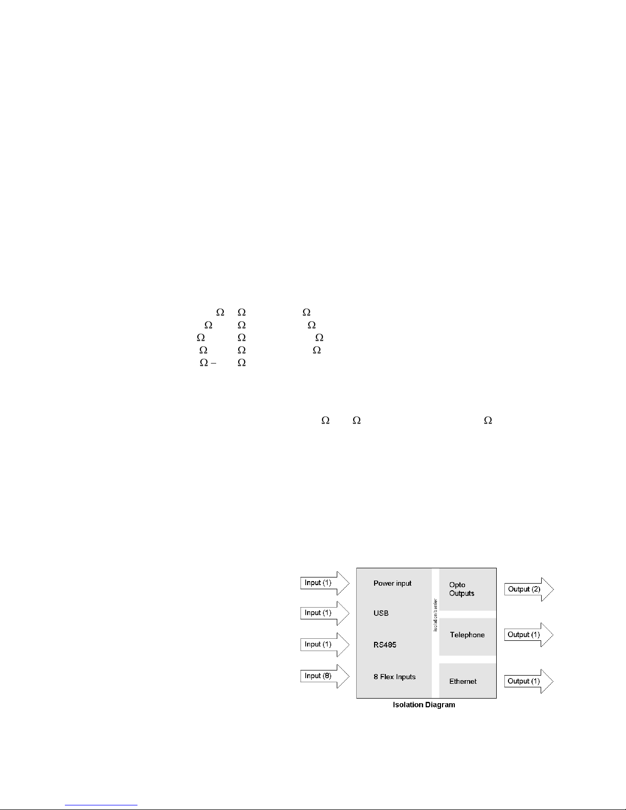
A8812 Features and Specifications ......................................................................................................................................................6
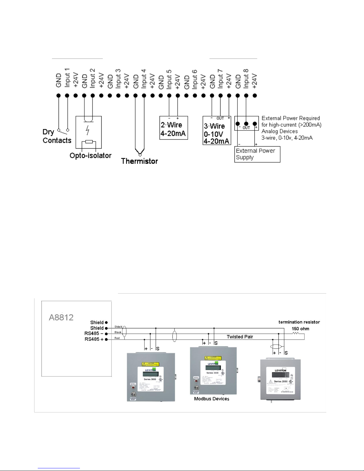
Electrical Connections..........................................................................................................................................................................7
Hardware Installation ...........................................................................................................................................................................7
Basic Network Configuration......................................................................................................................................................................... 10
Laptop/Computer Setup......................................................................................................................................................................11
Energy Monitoring Hub Administration Overview ........................................................................................................................................ 13
Security........................................................................................................................................................................................................... 14
Modbus........................................................................................................................................................................................................... 14
Modbus Device List ...........................................................................................................................................................................14
Device List Options................................................................................................................................................................15
Device Details........................................................................................................................................................................16
Device Configuration.............................................................................................................................................................16
Advanced Configuration Options...........................................................................................................................................16
Manual Device Add Options..................................................................................................................................................17
Internal IO Configuration.......................................................................................................................................................18
Troubleshooting Modbus Devices......................................................................................................................................................20
Modbus Setup.....................................................................................................................................................................................20
Alarm Setup........................................................................................................................................................................................21
Modbus Framework............................................................................................................................................................................22
Wireless.......................................................................................................................................................................................................... 22
Sensor List..........................................................................................................................................................................................22
ModHopper Map................................................................................................................................................................................22
Networking..................................................................................................................................................................................................... 23
Network Status...................................................................................................................................................................................23
Ethernet setup.....................................................................................................................................................................................23
Troubleshooting Ethernet Problems ...................................................................................................................................................23
System Options............................................................................................................................................................................................... 24
Status..................................................................................................................................................................................................24
Processes ............................................................................................................................................................................................24
Date and Time....................................................................................................................................................................................24
Universal Time Is Your Friend...............................................................................................................................................24
System logs ........................................................................................................................................................................................25
Firmware Update................................................................................................................................................................................25
Diagnostics..................................................................................................................................................................................................... 26
Host Lookup.......................................................................................................................................................................................26
Connection Test..................................................................................................................................................................................26
LCD Console.................................................................................................................................................................................................. 27
Log File Data.................................................................................................................................................................................................. 28
Log File Status....................................................................................................................................................................................28
Log File Format..................................................................................................................................................................................29
Log Storage Capacity.........................................................................................................................................................................30
Uploading data to the LEM website...................................................................................................................................................31
Retrieving Data from the Energy Monitoring Hub......................................................................................................................................... 32
HTTP Direct from the Energy Monitoring Hub .................................................................................................................................32
FTP Direct from the Energy Monitoring Hub ....................................................................................................................................32
Enertrax download direct from the Energy Monitoring Hub..............................................................................................................32
HTTP/Post Upload To Energy Manager ...........................................................................................................................................33
HTTP/Post Upload To Your Database Server....................................................................................................................................34
Removing Data from the Energy Monitoring Hub.............................................................................................................................34
Linking to Energy Monitoring Hub Device Status Pages...................................................................................................................34
Mechanical Drawings..................................................................................................................................................................................... 35
Shop for Power Metering products online at: 1.800.561.8187
www.PowerMeterStore.ca

Overview
The Energy Monitoring Hub™ Data Acquisition Server is designed to allow owners and managers of commercial and
industrial facilities with a cost-effective means of gathering crucial information in a timely manner. To meet these
requirements, the Energy Monitoring Hub™ system provides the installer with all the tools necessary to install and
configure the hardware and software with a minimum of time and investment.
Installation Checklist
An Energy Monitoring Hub™ system installation has the following components:
Required hardware
Energy Monitoring Hub™ A8812 Data Acquisition Server (required)
Data connection (Ethernet).
Ethernet Cat 5 cable (required for LAN or direct laptop-to-Energy Monitoring Hub connection)
Optional hardware
Leviton Series 2000 and 3000 meters (Modbus RTU standard).
Analog sensors for temperature, humidity, etc.
Pulse output transducers for measuring gas, electricity, water, etc. from existing meters and sensors.
Next, choose one or more of the following connection methods.
For LAN installations only:
Ethernet 10/100Mbit connection point (hub or switch)
IP address and Netmask (check with system administrator)
Gateway address (check with system administrator)
DNS server address (check with system administrator)
HTTP Proxy address (optional), may be required if the Energy Monitoring Hub is behind a firewall (check with
system administrator)
Markings and Symbols:
WARNING: A potential risk exists if the operating instructions are not followed
General Warning Symbol: This symbol indicates the need to consult the operating instructions provided with the
product.
This symbol indicates the presence of electric shock hazards.
This symbol indicates: Do not apply to or remove from hazardous live conductors.
Direct Current symbol.
Shop for Power Metering products online at: 1.800.561.8187
www.PowerMeterStore.ca

Hardware Overview
A8812 Features and Specifications
Processor Arm9 embedded CPU, Arm7 io coprocessor
Operating System Linux 2.6
Memory 32 MB ram, 16 MB flash
LED 8x input, 4 modem activity, Modbus TX/RX, power, system, io status
Console 2 x 16 character LCD, two pushbuttons
LAN RJ45 10/100 Ethernet, full half duplex, auto polarity
Protocols Modbus/RTU, Modbus/TCP, TCP/IP, PPP, HTTP/HTML, FTP, NTP, XML, SNMP-Trap
Power Supply 24VDC, 1A, class 2 wall brick transformer.
North America: 110-120VAC, 60hz, primary. (standard, included)
CE/Europe: 100-240VAC, 50-60hz, primary, with interchangeable plug adapters. (optional)
Interval Recording User selectable 1-60 minutes. Default 15 minute interval
Serial Port1RS-485 Modbus, supports up to 32 external devices (expandable)
Inputs18 flex-io inputs with multiple modes: voltage, current, resistance, pulse and status.
Voltage mode: 0-10vdc (min/max/average/instantaneous data)
accuracy: +- 0.25% of full scale at 20ºc
Current mode: 4-20mA (min/max/average/instantaneous data)
accuracy: +- 0.25% of full scale at 20ºc
Resistance mode: 100 ohms to 100k.
accuracy: 100 -1k +- 1% of 1k at 20ºc
1k –10k +- 1% of 10k at 20ºc
10k –47.5k +- 1% of 47.5k at 20ºc
47.5k –100k +- 1% of 100k at 20ºc
100k 10M accuracy unrated.
Pulse mode: intended for use with dry contact outputs. (consumption/rate/runtime/status)
Standard and KYZ modes for form A and C relay outputs
Input terminal supplies 3V ~ 5V at 5mA sense voltage to detect contact closures.
Maximum rate: 10hz, minimum pulse width 50ms.
Adjustable contact closure threshold: 100 to 5k , broken wire sense above 10k optional.
Pulse count and runtime values are stored in non-volatile memory.
Outputs1: 2 optically isolated outputs type: opto-fet, dry contacts. Rating: 30vdc, 150mA max.
Isolation2: The RJ45 Ethernet, RJ11 Modem, pulse outputs, and the primary side of the power adapter are
electrically isolated from the Energy Monitoring Hub main PCB board and inputs.
Environmental North America: Indoor, temperature 0º - 50ºc, 0 - 95% humidity, non-condensing.
CE/Europe: Indoor, temperature 5º - 40ºc, 0 - 90% humidity, non-condensing.
EMC FCC CFR 47 Part 15, Class A
EN 61000, EN 61326
Size 8” x 9.25” x 2.5” (203mm x 235mm x 64mm)
Mass 5lbs (2.3kg)
1inputs are intended for low voltage class 2 outputs.
2if the product is used in a manner not specified by the
manufacture, the protection provided by the equipment
may be impaired.
A8812
Shop for Power Metering products online at: 1.800.561.8187
www.PowerMeterStore.ca

Electrical Connections
Not available with
this model
A8812 Internal View
Hardware Installation
Step 1 - Unpack materials: Remove all materials from shipping box and verify all required components are available
Step 2 - Mount the Energy Monitoring Hub on the wall or other appropriate location.
Shop for Power Metering products online at: 1.800.561.8187
www.PowerMeterStore.ca

Step 3 –(optional) Connect any analog or pulse output sensors you may have. For Analog sensors, 0-10V or 4-20mA sensor
types are allowed. The combined power consumption of all the analog sensors attached to the Energy Monitoring Hub must
not exceed 200mA. If more current is required, use an external power supply as shown in the wiring diagram for each input
type later in this section.
Step 4 (optional) - Connect the Modbus network loop as shown in the wiring diagram. Follow the manufacturer‟s
instructions for installing and powering the Modbus devices. Verify that the Modbus address settings are unique for each
device (i.e., no two devices with the same address) and power up the device. Connect each device in the chain by “daisy-
chaining” the devices together. Observe + and - polarity on the Modbus devices.
Low Voltage analog, pulse, and RS485 wiring that enter electrical panels must have a minimum insulation rating that
exceeds the voltage inside the panel. In addition, other regulations may apply; consult the building codes in your area prior
to installation.
The RS485 port on the A8812 has a built in terminator. A 150 ohm termination resistor should be placed at the other end of
the RS485 loop, between the + and –wires.
Note: Some Modbus devices do not use the same label notation as the Energy Monitoring Hub.
The Energy Monitoring Hub A8812 internal IO module (Analog and pulse inputs) uses Modbus address 250, and will show
up in the Modbus device count as a single Modbus device. Additional analog or pulse input IO modules may be added to the
Modbus loop as needed.
Energy Monitoring Hub
Modbus loop as needed.
Energy Monitoring Hub A8812
Shop for Power Metering products online at: 1.800.561.8187
www.PowerMeterStore.ca

Step 5 - Power-up and diagnostics: Attach the power supply to the power input jack on the Energy Monitoring Hub, and
plug the power brick into a wall outlet. The power brick should be in a location that is accessible for connection and
disconnection. After power is applied, the green “Alive” light in the upper right of the Energy Monitoring Hub should come
on and the LCD display will display a series of diagnostic screens ending with the following message on the LCD display
(this boot sequence may require up to 20 seconds to complete):
AcquiSuite Ready
192.168.40.50
This indicates that the Energy Monitoring Hub has loaded properly and is ready for configuration and connection to the
network and sensors. If the “Alive” light does not come on or the LCD display does not cycle to the above screen, verify
that the power cord is plugged in. If after cycling the power the unit still does not power up (or if an error message appears
in the LCD display), contact technical support. After the A8812 has been powered up for a minute, the green Alive LED
should blink slowly once per second during normal operation.
Modbus TX/RX: The Modbus TX and RX LEDs blink to indicate data on the RS485/Modbus loop. The
RX led blinks only when data is received by the Energy Monitoring Hub
Modem RTS: the modem is being monitored or operated by the Energy Monitoring Hub, off when the
modem is idle. This LED will be on when a dialout call is in progress, or when dial in is enabled and
waiting for an inbound call.
Modem CD: the modem has a carrier connection to a remote system.
Modem TX/RX: data is being sent or received on the modem.
Alive: blinks once per second while the system is operating correctly.
Alarm: blinks to indicate a problem.
Inputs 1-8: in pulse or status mode, the LED is on when contacts are closed. In analog 4-20mA and 0-
10V mode, the led blinks quickly (2 Hz) to indicate an over-range alarm error. In 4-20mA mode when the
input current is less than 4mA, or in resistance mode where the input resistance is above 10Mohm, the led
will blink a pattern (blink, blink, off) to indicate a broken wire alarm.
Ethernet Link/Act: On when connected to a hub or switch, off when not connected. Blinks when LAN
traffic is being sent or received.
RS485 RX/TX. The 485TX led should blink slowly once per second during normal operation. The RX
led will blink when external Modbus devices communicate with the Energy Monitoring Hub.
RF TX / RF RX: If the A8812 has a built-in ModHopper option with an on-board radio, the RF LEDs
will blink showing transmit and receive packets.
Step 6 - Verify connected devices: To verify that the Modbus devices are installed and reporting correctly, use the Modbus
status utility on the Energy Monitoring Hub server. To do this test, follow these steps:
A. Press and release the menu (top) button on the Energy Monitoring Hub. The following will appear on the
LCD display:
[Main Menu]
TCP/IP Config
B. Press the menu (top) button several more times until the LCD display shows the following message:
[Main Menu]
Modbus Status
C. Press the select (bottom) button on the server and the unit will begin the diagnosis of the Modbus loop.
After the check is completed, the unit will display the following message:
X devices OK
X fail, X new
D. Verify that the number of devices located by the server (the total of OK, fail and new) matches the number
of devices actually installed and connected. For a first time installation, all devices should appear as “new”.
The Energy Monitoring Hub A8812 Internal IO (pulse and analog inputs) appear as one device in this list.
Shop for Power Metering products online at: 1.800.561.8187
www.PowerMeterStore.ca

(Note: A “device” is the Modbus connected device, not necessarily the sensor. For example, an A8923-4 I/O
module with 4 sensors connected is only one Modbus device, not four.) For further information on the LCD
console, please review the console section of this manual.
E. The Energy Monitoring Hub completes a background scan for new Modbus devices every 2-5 minutes.
Increasing the RS485 Modbus timeout may increase the time required to detect new devices. If the Modbus
devices are connected after the server is booted up, the devices may not appear on the screen for several
minutes. In the worst case, allow up to 5 minutes for the Energy Monitoring Hub to locate all the connected
devices.
F. If all devices are reporting properly, it is now time to connect the server to the network or phone line for
remote reporting and configuration.
Basic Network Configuration
Step 1 - Determine the IP addressing needs: The IP address of the Energy Monitoring Hub server can be implemented using
one of three methods. Check with the network administrator to determine which method applies. For phone installations, use
"direct connection to laptop" to allow initial configuration.
Static IP address - this is a fixed IP address which is assigned by a network administrator and “hard-coded” into the
Energy Monitoring Hub; or
Dynamic Host Configuration Protocol (DHCP) address - this process assigns an IP address dynamically to the
Energy Monitoring Hub when it is connected to the network from a host DHCP server; or
Direct connection between the Energy Monitoring Hub and a single temporary computer such as a laptop. (primary
connection will be dial in or dialout by modem)
You will need the following information from your network administrator: The addresses will be in the form of
“###.###.###.###”), where “#” refers to the numbers 0 to 9.
Static IP Address
DHCP
Direct Connection to Laptop
IP address: ___.___.___.___
Netmask: ___.___.___.___
Gateway: ___.___.___.___
DNS server: ___.___.___.___
HTTP Proxy _____________
proxy server port: ______
IP address: (dhcp assigned)
Netmask: (dhcp assigned)
Gateway: (dhcp assigned)
DNS server: (dhcp assigned)
HTTP Proxy _____________
proxy server port: ______
IP Address: 192.168.40.50
Netmask: 255.255.255.0
Gatway: 192.168.40.1
DNS: 70.99.203.62
HTTP Proxy: [blank]
(factory default settings)
Network Address Worksheet
Step 2 - Configure the IP address as selected from the table above. For Direct Connection to Laptop, the address settings
above are set as the factory default, and you may be able to skip to the "Laptop/Computer Setup" section if the factory
default settings are present.
To begin configuration, make sure that the server displays the start screen:
AcquiSuite Ready
192.168.40.50
If this screen does not appear on the LCD display, press and hold the menu (top) button on the server for several seconds
and the message should appear. To change the IP address to the static address assigned by the network administrator, do the
following:
A. Press the menu (top) button once to get the TCP/IP configuration menu
[Main Menu]
TCP/IP Config
B. Press the select (bottom) button twice to get the IP config menu:
[TCP/IP Config]
IP Address
Shop for Power Metering products online at: 1.800.561.8187
www.PowerMeterStore.ca

C. Press the select button again to see the IP address menu:
[IP Address]
192.168.40.50
D. At this point, the cursor on the display will be blinking on the first number in the IP address on the second
line.
E. To change the number, press the menu (top) button and the display will cycle through the digits 0-9 as well
as “.”. Once the correct digit is displayed, press the select (lower) button to advance to the next digit and
repeat the process until all the digits are correct.
F. Once the IP address on the Energy Monitoring Hub matches the assigned IP address; press the select
(bottom) button once more to return to the main TCP/IP menu.
Step 3 - Set the netmask, gateway, and DNS server(s) addresses as noted in the chart "Network Address Worksheet" using
the same technique as shown above. The only change is that after Step B; press the menu (top) button multiple times to see
the netmask, gateway, and dns setup menu, then push the select button to set the option.
Note: If DHCP configuration is selected, the IP, netmask, gateway, and dns server addresses will be obtained automatically.
Simply select the “Enable DHCP” from the first TCP/IP configuration menu.
Step 4 - After the address information has been set, you must reboot the Energy Monitoring Hub. Select the "(Previous
Menu)" option after step B above. The menu will then state that the Energy Monitoring Hub must be rebooted to take effect.
Press 'select' to allow the Energy Monitoring Hub to reboot.
Once the Energy Monitoring Hub has rebooted, the new IP address will be displayed on the console. If DHCP addressing
was specified, the server assigned address will be displayed.
Note: if DHCP is unable to obtain an IP address, the Energy Monitoring Hub will use the fallback address of 192.168.0.100.
Laptop/Computer Setup
Step 1 - You must have a computer to access and configure the Energy Monitoring Hub. This computer must have an
Ethernet connection (on the LAN or by direct connection) and must have a web browser installed such as Internet Explorer
or Netscape.
Note: If your building already has an existing LAN that the Energy Monitoring Hub is attached to, you can use an existing
computer on that LAN. Check with your network administrator for details. If this option is available, use a LAN connected
computer and skip to the “Energy Monitoring Hub administration overview” section below.
LAN connected EMH Direct Connect EMH
EMHEMH
The remainder of this section will assume the installer has brought a laptop to the site, and will connect the laptop to the
building LAN, or directly to the Energy Monitoring Hub. Attach the laptop to the Energy Monitoring Hub or LAN as shown
in figure 6, Ethernet hookup.
Step 2 - Attach the Laptop to the Energy Monitoring Hub or to the LAN. The A8812 will automatically detect whether a
direct or crossover cable is required, and will reverse polarity accordingly. This feature will allow you to use either a
straight Ethernet cable or a crossover Ethernet cable interchangeably.
Shop for Power Metering products online at: 1.800.561.8187
www.PowerMeterStore.ca

If the Laptop is to be attached to an existing LAN, obtain a static IP address (or use DHCP addressing) from the network
administrator.
Static IP Address for the laptop
DHCP
Direct Connection to Laptop
Specify an IP address
IP address: ___.___.___.___
Netmask: ___.___.___.___
Obtain an IP address automatically.
(All other required settings are assigned
by the DHCP server)
IP Address: 192.168.40.1
Netmask: 255.255.255.0
(Energy Monitoring Hub factory default
settings)
Laptop Address Worksheet
Step 3 - Configure the laptop IP address using the following steps. Note: Only Windows XP is detailed below; however you
can use any OS/Browser you wish such as MacOS or Linux. Detail on network setup for non-windows operating systems is
beyond the scope of this document however.
A. From the Windows start menu, select the
"Settings”, “Network Connections" option.
Double click the 'Local Area' network
connection icon in the network folder, then click
the "Properties" button.
B. In the network setup dialog, there should be a
list of items including adapters, clients and
protocols. Locate the item labeled “Internet
Protocol (TCP/IP)".
Note: If you have multiple Ethernet cards, you
may have multiple lines labeled "TCP/IP --> Ethernet card". Locate the Ethernet card that corresponds to the
physical connection to the Energy Monitoring Hub and then select the TCP/IP option that is linked with that
Ethernet card.
C. Double click the TCP/IP option you selected in step B above. The
Internet Protocol properties dialog will be shown. This page allows
you to select DHCP (obtain an IP address automatically) or
configure an address manually.
D. Select the option for “Use the following IP address” as shown in the
picture to the right. Set the IP and Netmask from the Laptop
Address Worksheet above. It would be helpful to make note of your
previous settings in this dialog so you may set them back after you
are done with the Energy Monitoring Hub Configuration.
E. Close the TCP/IP settings dialog, and Network dialog.
Shop for Power Metering products online at: 1.800.561.8187
www.PowerMeterStore.ca

Energy Monitoring Hub Administration Overview
The Energy Monitoring Hub should now be available on the local area network for you to access using a web browser such
as Internet Explorer or Netscape.
Step 1 - Use your web browser to connect to the Energy Monitoring Hub by entering
http://192.168.40.50/setup/
Where 192.168.40.50 is the IP address displayed on the on the Energy Monitoring Hub LCD display.
Step 2 - When prompted, use the following default login information
Login: admin
Password: admin
Step 3 - Your web browser should now display the Energy Monitoring Hub configuration menu. To the left, a list of
configuration options is available. On the right, a specific configuration page will be shown. The first page is a welcome
message with some system status information. Proceed with the configuration of the Energy Monitoring Hub using your
web browser.
Step 4 - Click on the +mark next to the Accounts menu. Select the Admin account, and click 'Change Password'. All units
are shipped with the same factory default password, and it should be changed to prevent unwanted access.
Step 5 - Expand the Networking option, and select setup. Verify the addresses are consistent with those in the "Network
Address Worksheet."
Step 6 - Expand the Modbus option, and select "Device List." You should see a list of each Modbus device attached to the
Energy Monitoring Hub. Before the Energy Monitoring Hub can begin logging data, each Modbus device must be assigned
a unique name.
A. Click the device number to the left of the unconfigured Modbus device.
B. A page with the current device status and readings will be displayed. Click on the 'configure' button at the bottom
of the page.
C. Enter a name for the device in the supplied field.
D. Change any low and high range alarm settings you may need. (optional)
E. Click the 'Save' button at the bottom of the page to save your changes.
F. Repeat these steps for each Modbus device.
Some devices may require additional information. For example, the Veris H8238 Multi circuit power meter allows the CT
size to be specified. The Leviton A8332 Module and the A8812 Energy Monitoring Hub internal IO module have additional
configuration options on each data point line to specify the details of the analog or pulse input. These include the 4-20mA
device scale, multipliers and engineering units. Each 4-20mA or 0-10Vsensor should be supplied with technical information
including the low and high range values that can be used to configure the Energy Monitoring Hub. Also, the Energy
Monitoring Hub has many common sensor types pre-programmed that can be selected from a drop down list. Review the
Modbus Advanced Configuration Options section of this manual for further configuration details.
Step 7 - Select the Modbus/Setup menu option. Specify the Modbus Loop Name. This will become the name of the Energy
Monitoring Hub. This is the name that will appear on the LEM website service (if subscribed). Specify the data logging
period. The default is 15 minutes.
Step 8 –Decide upon a method of data transfer. (see section later in this document) . If you select the HTTP/Post method to
send data to the LEM website, you can configure this by selecting the “LogFileData, Setup/Upload” page.
A. Make note of the Energy Monitoring Hub serial number.
B. Select upload options as needed for time of day to upload the data and retry control.
C. Check the checkbox to allow remote configuration. This will allow you to reconfigure the Energy Monitoring Hub
from the LEM web site without having to connect directly to the Energy Monitoring Hub.
D. Specify the "Target address to upload data." This is the website address where the Energy Monitoring Hub will
send the collected data. If you have an in-house data collection service, you should enter the address of your data
server in this field. Leviton also provides a service called Building Manager Online that can collect and report data
for you. If you are using the LEM service, the target address to upload data should be set to
http://www.buildingmanageronline.com/upload.php
E. When configuring the Energy Monitoring Hub to send data to the LEM site or your own data collection server, the
Energy Monitoring Hub will authenticate itself with the server by using the serial number and a password. This
password must be supplied here, and can be obtained when you subscribe for the LEM service, or by your database
administrator.
Shop for Power Metering products online at: 1.800.561.8187
www.PowerMeterStore.ca

F. Click "Apply" to save your changes.
If you select a manual transfer method, remove (blank out) the target address in the Modbus/Upload Data page.
Security
The Energy Monitoring Hub has three levels of security. These are “operator”, “user” and “admin”. When using a browser
to access the Energy Monitoring Hub, basic http authentication is used to prompt your browser for a username and
password. The admin account uses “admin” as the default password. To change the password, select the Accounts menu
from the left side tree display. Next, select the account name. Click the “Change Password” button to set a new password
for the selected account.
admin: This account has full access to modify any of the system settings. The default password is “admin”.
operator: This account may view settings, however may only change Modbus alarm ranges and device names.
user: This account can view some system settings including the Modbus device status pages and can change nothing.
When using FTP to access the Energy Monitoring Hub, you may use the admin account username/password for read-only
access. Log information is stored in /var/log/Modbus. For read-write-delete access, use the login name “root” and the
admin password.
The three usernames specified are not able to be changed or renamed, nor can arbitrary usernames be added to the Energy
Monitoring Hub. Access is only controlled by setting the password for the three existing usernames noted above.
The “operator” and “user” accounts are disabled by default. These accounts are activated when you first set a password for
each.
Modbus
Modbus Device List
The Energy Monitoring Hub automatically searches for Modbus devices on the RS485 serial loop. The Modbus Device List
page will show a listing of all the currently detected or configured devices the Energy Monitoring Hub has found. The
device list will show the Modbus address number, status (Ok, Error, Alarm, Unconfigured), the device name (user specified)
and the device identification string.
Click on the Modbus address number for any of the devices for specific device details
Note: not all Modbus devices have built in driver support in the Energy Monitoring Hub. If a device appears in the list with
“Unknown” in the status column, you may need to upgrade the firmware on the Energy Monitoring Hub to access the
device. At the bottom of the device list page under the Type column, a link is shown that will show all the Modbus devices
with built in driver support provided in the firmware. Use the System/Firmware update page to check for newer versions of
Shop for Power Metering products online at: 1.800.561.8187
www.PowerMeterStore.ca

the firmware.
At the bottom of the device list, there is an option to allow you to rename all the devices listed. This is useful for initial
deployments. There is also a troubleshooting link that will look for common configuration problems and alert you to the
appropriate solution.
Device List Options
At the top of the Modbus device list page, there are several display options that control the sorting of the device list.
Tree display: Click this icon to organize the list by showing each ModHopper, and the devices attached to each
one.
List display: (default) Show the list of Modbus devices sorted by the Modbus address number.
At the bottom of the Modbus device list, there are several options that may be selected to view or configure all the
Modbus devices at the same time. These options are as follows:
Add: Manually add a Modbus device to the device list. This option can be used to configure a Modbus device that is not
presently connected to the system, add a framework configured device, or add a Modbus/TCP connected device. See the
section on manually adding a device below.
Troubleshoot: The Energy Monitoring Hub will review the devices connected and offer suggestions about any problems
found.
Rename all devices: This option allows you to edit all the device names in one configuration page. This is useful when
initially configuring a large number of new devices. A name must be assigned to a device before the Energy Monitoring
Hub will log data for it.
List all supported devices: This option will show a list of all Modbus devices with built in drivers in the installed firmware.
Show [setup]: Display links for Device configuration and Advanced configuration for each device.
Show [devinfo]: Display the communications options including baud rate, serial number and firmware version (when
available) for all devices in the Modbus device list.
Show [stats]: Show packet counters for all devices in the device list. These include
Sent: Total number of packets sent to this Modbus address.
Received: Total number of valid packets received from this Modbus address.
Error: Total number of packets received that fail CRC for this device. (does not include non-response
queries)
RTT: The average round trip time for the last 7-10 packets that received a valid response. This value is useful
in configuring the Modbus timeout in the Modbus Setup/RS485 page. Note: if the timeout is set too short,
you will not see an accurate value because packets dropped for timeout are not counted for RTT.
XML: Display the device list data in XML format.
Notes on RTT and Timeout configuration:
To best measure the true RTT, set the Modbus Setup/RS485 timeout to the maximum period and allow the Energy
Monitoring Hub to run for 5 or 10 minutes. Next, review the RTT values seen in the device list page and make note of the
longest RTT time shown for any device. Last, configure the Modbus Setup/RS485 timeout to the option that is the next
largest than the longest time seen for any device. For example; if the worst RTT is 600ms, set the timeout to 1second.
Typical RTT values for direct connected devices should range between 40ms and 200ms. Systems that have wireless links
such as ModHoppers should expect an additional delay of 500ms per hop. A complex system with multiple ModHoppers
may have RTT values upwards of 3 seconds.
Shop for Power Metering products online at: 1.800.561.8187
www.PowerMeterStore.ca

Device Details
The device detail page will show a list of all the meter data points, alarm settings and console options. The data point names
for most devices are automatically entered. Some devices such as the A8332 io module have generic inputs, and will be
labeled as “pulse input #1”. At the top of the page, the status of the device is shown. This usually reports “ok” however it
can include error information if the device is not responding properly. A list of device errors is available in the log file
details section of this manual. At the bottom of the page, several buttons are present.
Done: Returns you to the device list page.
Log File: This icon will display a table view of the most recent data in the current log file. Use the log file export page for
complete log data access.
XML: This icon will show the current data from the Modbus device in an XML format. The URL from this icon can be
copied and used to gather xml data for client side Javascript or Java applications.
Configure: This button will allow you to change the device parameters such as the name, alarm and console settings.
Device Configuration
When the “configure” button is clicked from the device details page, the screen will be refreshed, with the same
information, however the device name, alarm settings and console checkbox will be available.
Device Name: This field allows you to specify a name for the device such as “main building power” or other useful name to
indicate the location or function of the device. A name must be assigned to a device before the Energy Monitoring Hub will
log data for it.
Low Alarm, High Alarm: Specify a threshold for the alarm. If the data point is recorded below the Low Alarm or above
the High Alarm levels at the time a log entry is taken, the point will be considered in an alarm state.
Console: Checking this checkbox will cause the Energy Monitoring Hub to display this data point on the LCD console.
Multiple data points are rotated about every 10 seconds. The values on the LCD console are updated when the next log
interval occurs.
Point Config: Some devices have configurable point features. The A8332 IO module has 4 pulse and 4 analog inputs that
require additional configuration as detailed in the next section. The H663/704 BCM product only requires the circuit
breaker name in this menu. Most data points are automatically configured and this option may not be displayed.
Advanced: At the lower right corner of the page, an advanced configuration button may be present depending on the
Modbus device features.
Advanced Configuration Options
The advanced configuration page contains special options specific to the device you are configuring. For the A8332 io
module, you may specify the pulse rate speed that the pulse inputs will work at, as well as review the 4-20mA/0-10v input
status. On power meters, the CT size and orientation options may be present. The device serial number and other specific
parameters will be displayed if available.
Specific options available in the Advanced Configuration page vary depending on the features available in the Modbus
Device, as well as the features implemented in the built in Energy Monitoring Hub driver.
Shop for Power Metering products online at: 1.800.561.8187
www.PowerMeterStore.ca

Manual Device Add Options
Modbus devices may be added manually by clicking on the “add” link on the bottom of the Modbus device list page. This
option is intended for use when adding devices to the configuration profile prior to installing the physical hardware, or
configuring Modbus/TCP devices that will not automatically populate in the Modbus device list.
The manual setup page has several options that must be configured before the Energy Monitoring Hub will recognize the
Modbus device. The options are as follows:
Modbus Address: The Modbus device address must be supplied. Note: when configuring a device on a remote
Modbus/TCP gateway, the Modbus address of the remote device must not be the same as any address on the local RS485
loop.
Modbus/TCP Gateway IP: This option allows the Energy Monitoring Hub to log data from a remote Modbus device that
is attached to the LAN via a Modbus TCP gateway device such as an EGX or Moxa gateway. For local Modbus devices
attached to the Energy Monitoring Hub RS485 port, use “127.0.0.1”.
Modbus/TCP Gateway Port: If a remote Modbus/TCP gateway is used, the TCP port of the remote gateway must be
specified. The default TCP port is 502 on most gateways. For local Modbus devices attached to the Energy Monitoring Hub
RS485 port, use 502.
Device Name: You must provide a name for the Modbus device to identify it in the device list. This should be something
that will identify the meter location and purpose.
Device Type: This menu will allow the selection of any built in driver or any Modbus Framework template that is available
on the Energy Monitoring Hub. It is important to select the driver or template that matches the Modbus device.
Note: Up to 32 remote Modbus/TCP devices may be added to the system. Because of addressing the devices on the Energy
Monitoring Hub device list, each Modbus/TCP device must have a unique ID in the same way that Modbus/RS485 devices
do.
There is no hard limit on the number of Modbus/RS485; however typical systems should not exceed 64 total devices for
performance reasons. Depending on the Modbus/RS485 device, the RS485 line may limit the system to 32 physically
attached meters, but can be expanded with the use of either ModHoppers or RS485 repeaters. The Modbus addressing
system on some meters will only allow addresses between 1 and 64, the Modbus Protocol requires the address be between 1
and 256.
Shop for Power Metering products online at: 1.800.561.8187
www.PowerMeterStore.ca

Internal IO Configuration
The A8812 Energy Monitoring Hub provides 8 multipurpose flex inputs on board. The onboard io inputs will always be
device 250 in the device list.
1. Click on the device number 250 in the device list. A page showing the device inputs will be presented. Each input has
5 lines on this page. Analog inputs have one line each for an instantaneous, min, max and average value. Pulse inputs
have a line for the accumulated value, rate, runtime and status.
2. Click the Configure button at the bottom of the page. The page will be displayed again; however the device name and
alarm level fields will allow editing.
Type in a name for the device in the space provided at the top of the page. The name should describe the purpose or
location of the IO module. For device 250, you may want to use the name “Internal IO”
3. For each input that you wish to use, click the “Config Point” button to the right of the input.
4. The input configuration requires several options. The input mode will control how the input functions. This includes
measuring voltage, current, resistance, pulse, or runtime. Use the dropdown menu to select the mode that is appropriate
Shop for Power Metering products online at: 1.800.561.8187
www.PowerMeterStore.ca

for your sensor. The input configuration must be completed for each input that is in use.
Sensor Name: change this to describe the input. This can be anything you wish, such as “Indoor Temperature”
Input Mode: Select from one of the following: Voltage 0-10v, Current 4-20mA, Resistance, Pulse, Pulse-KYZ, status
or Unconfigured.
Sensor Make and Model: This entry is a space for the model number of the sensor. It is only used for reference.
Sensor Minimum Range: All Analog Sensors have min/max range values. For example, a temp sensor may have a
range of 50 to 95 degrees F. Enter the low range number here.
Sensor Maximum Range: Enter the high range value of the analog sensor here.
Pulse Multiplier: For pulse mode inputs, this option specifies the multiplier for the input.
Curve Scaling: Some sensors such as thermistors have a non-linear output. This option allows a lookup table to be
specified to convert from the input reading to an engineering unit data output. Several conversion tables (Curve Scale
Templates) are provided with the Energy Monitoring Hub.
Pulse Rate: For most units, this feature is an automatic rate field. For KWH points, the rate is KW.
Engineering Units: Enter the units of measure. ie, Degrees F, %RH, etc.
5. After saving the sensor profile, the device configuration page will be displayed again. The input values should now be
scaled correctly and the names will be updated to your new configuration. You may wish to set any alarm thresholds
required, or check the “console” check box for any data points that should be displayed on the LCD console.
6. Click the “Advanced” button in the lower right corner of the page. For the A8812 onboard IO, there are several options.
Input types: This list shows the status of the 8 analog inputs, either 0-10V, 4-20mA, resistance, pulse, status, etc.
The Contact Closure Threshold allows you to set a maximum resistance to be counted as a “closed” contact. This is
helpful when using intrinsic barrier devices.
The Contact Open Threshold can be used in conjunction with a 20K resistor in parallel with the contact closure. When
the contact is open, the Energy Monitoring Hub will read 20K, when closed, it will read <100ohms. If the wire is broken,
the reading will go above 20k ohms, and will cause an alarm condition.
The Pulse count for instantaneous rate value specifies the number of pulses to use to calculate the instantaneous rate,
min, and max fields in pulse mode.
7. After returning to the device configuration page, click “Save” at the bottom of the page to return to the device display
page.
The internal I/O device 250 is also available to the Modbus TCP gateway feature. External systems such as computer
software or PLC may send a Modbus TCP query to the Energy Monitoring Hub using Modbus address 250. The internal
I/O device will respond with Modbus registers that represent all of the features seen in the Energy Monitoring Hub
configuration pages.
Shop for Power Metering products online at: 1.800.561.8187
www.PowerMeterStore.ca

Troubleshooting Modbus Devices
If the device you have attached does not appear in the Modbus device list, check the following:
Verify the + (red), - (black), and Shield connections are correct on all connections. Look for any connection in the
middle of the loop that may have the wires reversed, or shorted together.
Verify the address settings of every Modbus device. No two devices may have the same address. Note: the Energy
Monitoring Hub A8812 uses the address 250 for the internal IO module. Do not assign this address to any other Modbus
device.
If only one device is not working, try disconnecting all the other devices on the Modbus loop to isolate the problem. If
possible, bring the failed device adjacent to the Energy Monitoring Hub and attach it with a short stub of wire to
eliminate possible wiring problems. If the Energy Monitoring Hub can find a device on the short stub, the problem is
probably a wiring related issue on the RS485 loop.
Check to verify the Modbus device is supported by the Energy Monitoring Hub. Usually, the Energy Monitoring Hub
will locate the device and print “Unknown” in the device status column if the device is not recognized by the Energy
Monitoring Hub firmware drivers. In the lower right corner of this screen, there is a link that will show a list of
supported devices. Use this to verify the Modbus device in question is supported by the Energy Monitoring Hub
firmware version. If not, check for firmware upgrades online with the Firmware Update configuration page.
Remember, the Energy Monitoring Hub may take between 2 and 5 minutes to detect a new device that has been attached
to the Modbus rs485 loop. Rebooting the Energy Monitoring Hub, refreshing the device list page, or using the console
„Modbus status' menu will not speed up the recognition process.
Click the “Troubleshooting” link at the bottom of the Modbus device list page for further diagnostics.
Modbus Setup
The Modbus setup page provides several options related to the Modbus RS485 serial port.
Energy Monitoring Hub Name: This is the name of the Energy Monitoring Hub. This name will be present on all log file
descriptors when uploaded to a central database website such as LEM. It is helpful to name the Energy Monitoring Hub
based on the physical location of the system, or building. Note: this feature was labeled “Loop Name” in older firmware
versions.
Data logging period: This option sets the log interval for the Energy Monitoring Hub. Options range from once per minute
to once per hour. All of the selections are even divisions of one hour. The Energy Monitoring Hub calculates the next log
time by finding the next multiple of the log period past the start of the hour. For example, if the log period is 15 minutes,
log readings will be taken at 0, 15, 30 and 45 minutes past the hour. The log period is not calculated based on “15 minutes
after the last reading”
When the Energy Monitoring Hub is first started, it will take an initial reading of all the Modbus devices immediately.
Following that, the next log reading will be calculated as a multiple of the log period after the hour. The initial reading is
taken to allow the Energy Monitoring Hub to gather information for meters that require demand calculations, as well as
provide accurate information starting when the Energy Monitoring Hub is booted.
Modbus/TCP access: The Energy Monitoring Hub has a Modbus TCP gateway feature that allows other systems to send
queries to all attached Modbus RS485 devices. This feature allows control of what systems have access to the Modbus TCP
gateway feature. The settings include “no access”, “local subnet only” and “allow any”. This basic security feature only
allows control based on the IP address of the system making the request. The Modbus TCP protocol does not have
provisions for any authentication password or other methods of security. By default, the gateway feature is disabled, and set
to “No Access.”
The Modbus TCP gateway is a feature that allows the Energy Monitoring Hub to share the attached Modbus RS485 devices
with other systems such as PCs with software and building control systems. The gateway receives incoming TCP requests,
verifies the length of the packet does not exceed 255 bytes, and forwards the packet to the Modbus RS485 loop. The
gateway does not verify the contents of the packet, nor the target address specified in the request. If the Modbus RS485
device sends a valid response back, the gateway will return this information to the system requesting it via TCP. If no
response is received, a timeout failure will be sent to the requester. Because the gateway does not process the contents of
the request or reply, it is possible to query devices on the Modbus RS485 loop that are not specifically supported by the
Energy Monitoring Hub.
Modbus RS/485 baud rate: This feature allows the configuration of the RS485 serial port speed which the Energy
Monitoring Hub uses to communicate with Modbus devices. Options include 9600, 19200, 38400, 57600, and 115200. The
Shop for Power Metering products online at: 1.800.561.8187
www.PowerMeterStore.ca
Table of contents
Other Leviton Server manuals