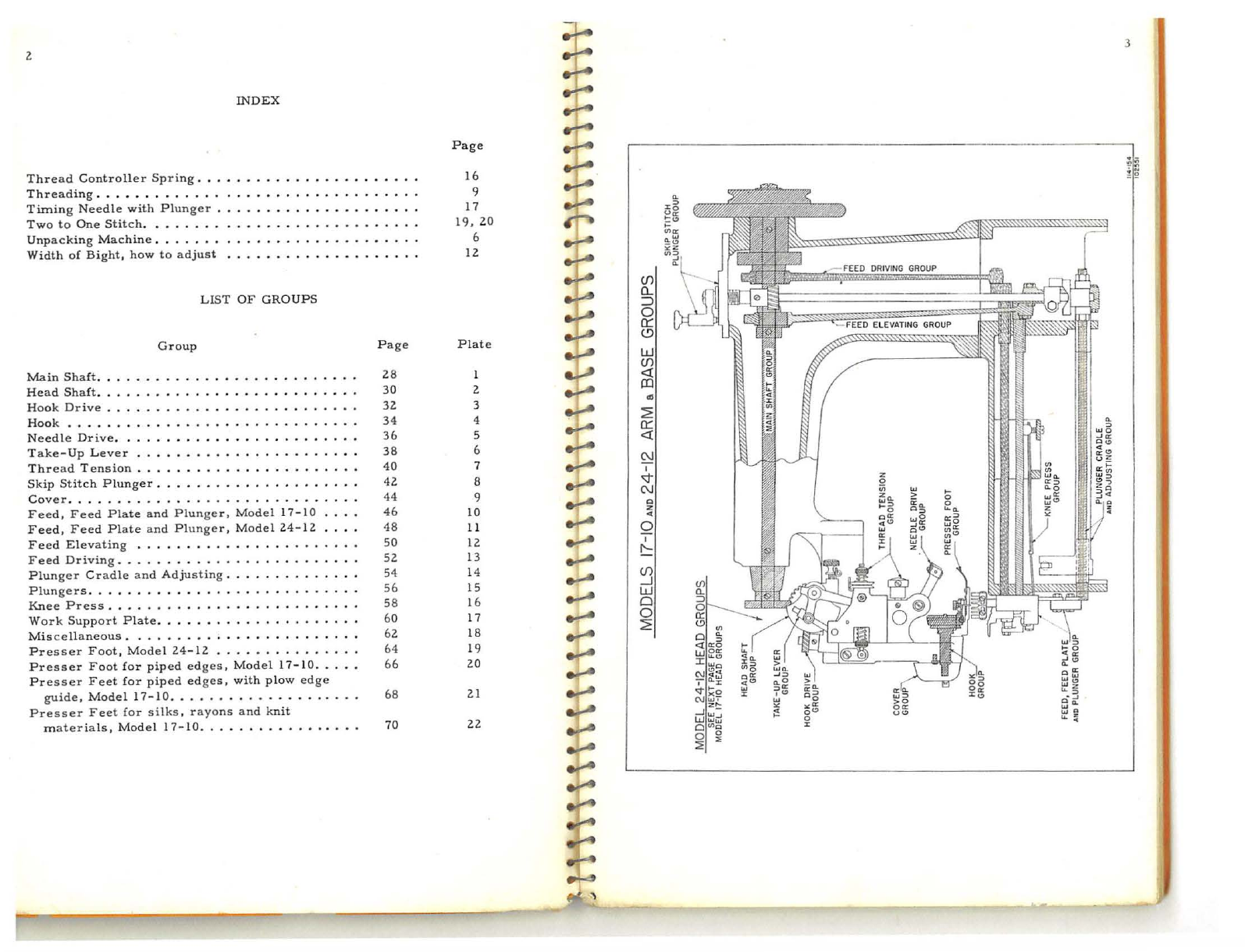
14
42..
To
remove
bobbin
case
,
we
recommend
that
the
presser
f
oot
be
rem
ove
d
first
as
per
ins
truc
ti
ons
in
Paragraphs
38
and
39.
Figu
re
G
Corr
ec
t
Po
s i
tio
n
of
Hook
for
Re
-
moving
Gib
Screws
and
Gib.
Figure
H
Gib
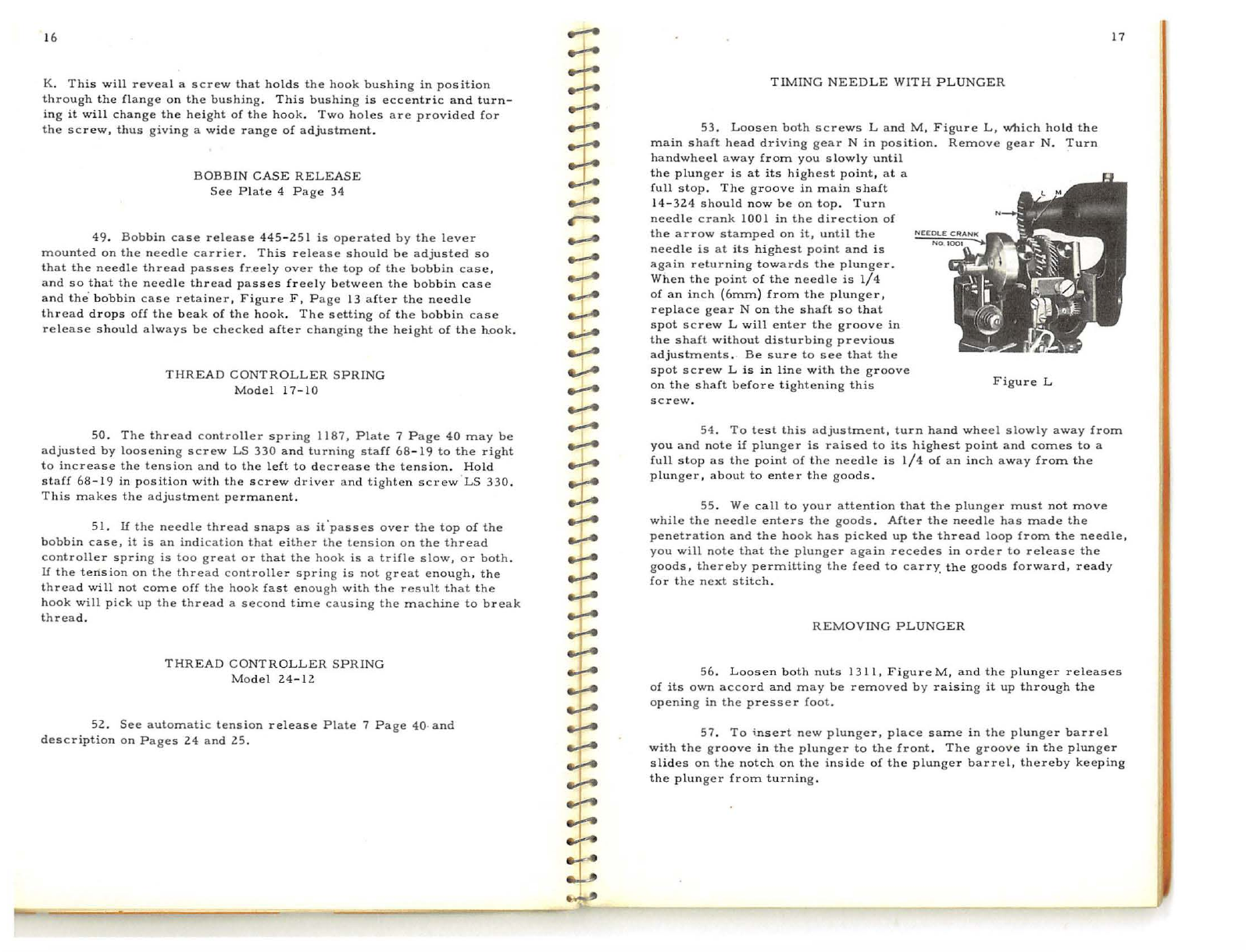
an
d
Scr
ew s
Removed
for
Bobbin
C
ase
Repl~cement.
Fi
gure
Rela
ti
ve
Position
of
the
Latch
to
t
he
Point
of
the
H
ook
For
Removing
Bobbin
Case.
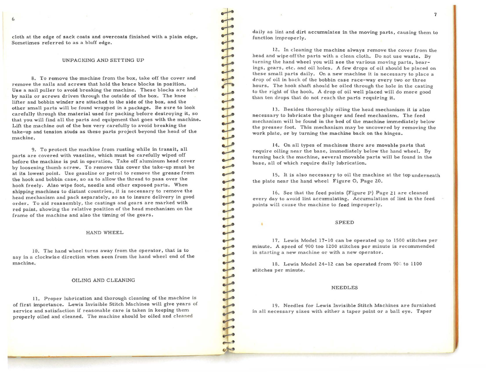
43
.
See
th
at
the
p
oint
of
th
e
hook
is
at
its
low
es
t p
oint
as
per
illustration
above.
Th
en
re
m
ove
both
g
ib
screw
s 1
039
which
holds
gi
b
1
037
in
p
os
ition
on
the
hook
. S
ee
Figur
e H.
After
re
m
ovi
ng
gi
b,
turn
bobbin
case
to
the
left
one
-qu
arter
turn
.
This
releases
the
b
obb
in
case
fr
om
the
hook.
44.
Inasmu
ch
as
the
·
bobbin
case
fits
snugly
in
the
r
aceway
of
the
hook
,.
it
may
be
necess
ary
to
use
slight
pr
essu
re
to
cause
it
to
release
.
Use
fingers
only
to
remove
the
b
obb
in
case
and
do
not
insert
screw
driver
or
any
other
object
as
a l
ever,
as
this
is
apt
to
break
the
b
obb
in
case
.
To
insert
bobbin
case
in
hook
,
see
that
the
latch
is
in
lin
e
with
the
point
of
the
hook
as.
per
illustration
,
Figure
I.
Replace
hook
gib
in
position,
and
secure
ly
tighten
screws
1039.
Turn
bobbin
case
so
that
the
groove,
Fi
gu
re
A,
is
at
the
bottom
and
fi
ts
into
the
n
otch
on
the
bobbin
case
retainer
as
no
ted
in
paragraph
40
.
REPLACING
AND
TIMING
HOOK
45
.
Re
mo
ve
gear
cap
1072.,
which
is
in
back
of
the
m
achine
in
lin
e
with
the
hook
.
Rem
ove
gear
1030,
Plate
3,
P
age
32.
,
by
loosening
both
screws
holding
same.
Remove
needle
and
presser
foot,
a s
per
inst
r
uc
-
tions
in
Pa
rag
raphs
38
and
39.
Remove
Bobbin
case
releas
e
445
-
2.51
by
removing
screw
which
ho
l
ds
same
in
position
.
With
these
various
parts
out
of
the
way
,
the
hook
can
be
withdrawn
from
Figure
J
Hook
10
40A
~
.......
~
~
.......
..,:.-e
.,.:...e
~
.,....
.,_;....e
.....-..
~
~
....-...
..,
--r-
..,
..,
--1
..,:..e
..;-.-
~
.-i-4
~
--0
.,;..e
.,;...e
...;-e
..,::A
~
~
~
~
~
..
.J_,
~
the
machine.
See
Plate
4,
Page
34.
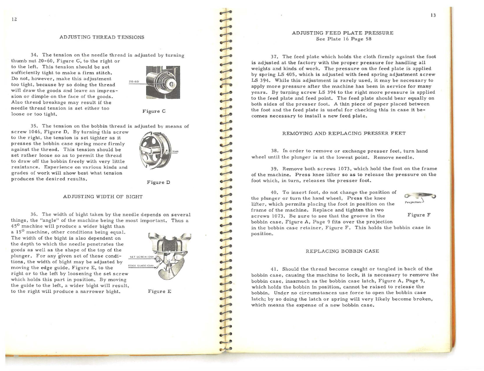
46
.
To
repla
ce
the
hook
preceding
instruc.tion
apply,
with
the
a
dded
ca
ution
regarding
timing
the
hook.
Th
is
is
a
simple
matte
r b y
noting
the
lin
es
on
both
the
upper
a
nd
lower
gears
102.8 a
nd
1030
,
Figure
K.
Both
of
th
ese
gears
have
lines
which
must
meet
and
make
a
strai
ght
line
.
The
groove
in
the
hook
shaft
must
also
be
in
st
r
aight
line
with
the
two
lines
on
gears
102.8
and
1030
,
so
that
the
po
int
of
spot
screw
1031
will
fit
into
the
groove
on
the
h
ook
shaft.
When
inser
ting
a
new
hook,
the
gr
oove
may
not
be
in
t
he
same
r
elative
posit
ion
as
in
the
one
removed,
which
will
throw
the
hook
out
of
time.
To
complete
the
adjustment
it
may
be
ne
ces
s a
ry
to
lo
osen
the
two
screws
that
hold
gear
102.8
in
posit
i
on
.
Turn
the
hook
slightly
to
the
r
ight
in
order
to
pick
up
th
e
threa
d
loop
more
q
uick
ly
from
t
he
needle;
or
tu
rn
the
hook
p i
ck
up
the
needle
thread
loop
more
slowly,
whichever
may
be
r
equi
r
ed
.
Figure
K
15
Tighten
the
t~o
screws
in
gear
102.8, m
aking
sure
this
with
gear
1030
but
without
excessive
backlash
.
gear
runs
freely
47
.
You
will
note
that
the
point
of
th
e
hook
when
prope
rl
y
timed,
will
be
at
its
lo
wes
t
po
in
t
or
i
mmediately
above
the
needle
a
nd
about
1/16
of
an
inch
from
th
e
eye
of
the
needle
when
the
need
le
is
on
its
return
or
back
stroke.
In
this,
as
with
all
other
ad
justments,
be
very
ca
re
fu
l
to
see
that
all
screws
are
securely
tightened
and any
parts
that
have
been
r
emoved
are
ca
ref
ul
ly
repl
ac
es
in
position
.
CAUTION:
Before
t
im
ing
hook,
make
sure
that
n
eed
le
is
co
rr
ectly
timed
wi
th
plunger,
see
p
arag
r
aph
53,
page
17.
RA
I
SING
AND
LOWERING
H
OOK
48.
The
hei
ght
of
the
hook
re\ative
to
the
needl
e
is
set
at
the
factory
and
gene
r
ally
r
equi
r
es
no
adjust
m
ent
.
In
case
it
does
become
necessary
t~
change
the
height
of
the
hook,
remove
gear
1030,
Figure
~
~
----~
------------~~
=
~~-
~--~------~--------
-
·-~~------------------------------------------------~-'
From the library of: Superior Sewing Machine & Supply LLC