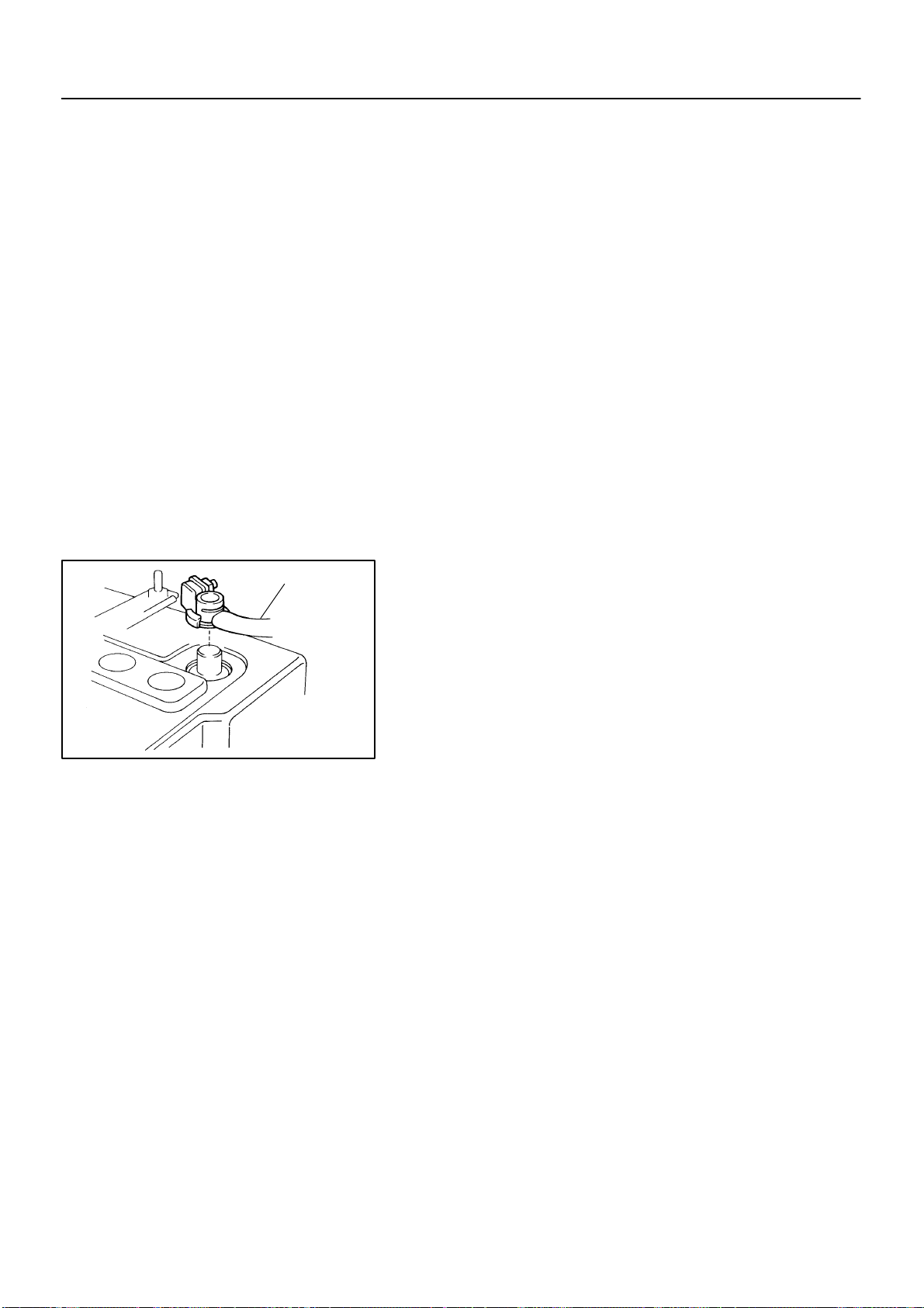
Lexus 2005 IS300 User manual

IN00U-90
N17080
Filler Cap
Float
Reservoir Tank
Grommet
Clip
Slotted Spring Pin
: Specified torque
Non-reusable part
Cylinder
Piston Push Rod
Washer
Snap Ring
Boot
Gasket
Lock Nut
Clevis Pin
Clevis
N·m (kgf·cm, ft·lbf)
12 (120, 9)
15 (155, 11)
-INTRODUCTION HOW TO USE THIS MANUAL IN-1
1Author: Date:
2005LEXUS IS300 (RM1140U)
HOW TO USE THIS MANUAL
GENERAL INFORMATION
1. INDEX
An INDEX is provided on the first page of each section to guide you to the item to be repaired. To assist you
in finding your way through the manual, the Section Title and major heading are given at the top of every
page.
2. GENERAL DESCRIPTION
At the beginning of each section, a General Description is given that pertains to all repair operations con-
tained in that section.
Read these precautions before starting any repair task.
3. TROUBLESHOOTING
TROUBLESHOOTING tables are included for each system to help you diagnose the problem and find the
cause. The fundamentals of how to proceed with troubleshooting are described on page IN-22 .
Be sure to read this before performing troubleshooting.
4. PREPARATION
Preparation lists the SST (Special Service Tools), recommended tools, equipment, lubricant and SSM (Spe-
cial Service Materials) which should be prepared before beginning the operation and explains the purpose
of each one.
5. REPAIR PROCEDURES
Most repair operations begin with an overview illustration. It identifies the components and shows how the
parts fit together.
Example:

Illustration:
what to do and where
21. CHECK PISTON STROKE OF OVERDRIVE BRAKE
(a)
Task heading : what to do
SST 09350-30020 (09350-06120)
Set part No. Component part No.
Detailed text : how to do task
(b)
Piston stroke: 1.40 1.70 mm (0.0551 0.0669 in.)
Specification
Place SST and a dial indicator onto the overdrive brake pis-
ton as shown in the illustration.
Measure the stroke applying and releasing the compressed
air (392 785 kPa, 4 8 kgf/cm2or 57 114 psi) as shown
in the illustration.
IN-2 -INTRODUCTION HOW TO USE THIS MANUAL
2Author: Date:
2005LEXUS IS300 (RM1140U)
The procedures are presented in a step-by-step format:
The illustration shows what to do and where to do it.
The task heading tells what to do.
The detailed text tells how to perform the task and gives other information such as specifications
and warnings.
Example:
This format provides the experienced technician with a FAST TRACK to the information needed. The upper
case task heading can be read at a glance when necessary, and the text below it provides detailed informa-
tion. Important specifications and warnings always stand out in bold type.
6. REFERENCES
References have been kept to a minimum. However, when they are required you are given the page to refer
to.
7. SPECIFICATIONS
Specifications are presented in bold type throughout the text where needed. You never have to leave the
procedure to look up your specifications. They are also found in Service Specifications section for quick ref-
erence.
8. CAUTIONS, NOTICES, HINTS:
CAUTIONS are presented presented in bold type, and indicate there is a possibility of injury to you or
other people.
NOTICES are also presented in bold type, and indicate the possibility of damage to the components
being repaired.
HINTS are separated from the text but do not appear in bold. They provide additional information to
help you perform the repair efficiently.
9. SI UNIT
The UNITS given in this manual are primarily expressed according to the SI UNIT (International System of
Unit), and alternately expressed in the metric system and in the English System.
Example:
Torque: 30 N·m (310 kgf·cm, 22 ft·lbf)

IN04P-27
B12091
A
B
B12487
2JZ-GE
-INTRODUCTION IDENTIFICATION INFORMATION IN-3
3Author: Date:
2005 LEXUS IS300 (RM1140U)
IDENTIFICATION INFORMATION
VEHICLE IDENTIFICATION AND
ENGINE SERIAL NUMBER
1. VEHICLE IDENTIFICATION NUMBER
The vehicle identification number is stamped on the vehicle
identification number plate and the certification label, as shown
in the illustration.
A: Vehicle Identification Number Plate
B: Certification Label
2. ENGINE SERIAL NUMBER
The engine serial number is stamped on the engine block, as
shown in the illustration.

IN0DC-15
FI1066
Z11554
Seal Lock Adhesive
IN-4 -INTRODUCTION REPAIR INSTRUCTIONS
4Author: Date:
2005LEXUS IS300 (RM1140U)
REPAIR INSTRUCTIONS
GENERAL INFORMATION
BASIC REPAIR HINT
(a) Prevent damage and maintain vehicle cleanliness by pro-
tective covering on the fender, seat and floor.
(b) During disassembly, line up parts in the order they were
removed to facilitate reassembly.
(c) Installation and removal of battery terminal:
(1) Before performing electrical work, disconnect the
negative (-) terminal cable from the battery.
(2) If it is necessary to disconnect the battery for in-
spection or repair, first disconnect the negative (-)
terminal cable.
(3) To prevent damage to the battery terminal when dis-
connecting the terminal cable, loosen the cable nut
and raise the cable straight up. Do not twist or pry
the cable off.
(4) Clean the battery terminals and cable ends with a
clean shop rag. Do not scrape them with a file or oth-
er abrasive objects.
(5) Install the cable ends to the battery terminals after
loosening the nut, and tighten the nut after installa-
tion. Do not use a hammer to tap the cable ends
onto the terminals.
(6) Be sure the cover for the positive (+) terminal is
properly in place.
(d) Check hose and wiring connectors to make sure that they
are connected securely and correctly.
(e) Non-reusable parts:
(1) Always replace cotter pins, gaskets, O-rings, oil
seals, etc. with new ones.
(2) Non-reusable parts are indicated in component il-
lustrations by the ”” symbols.
(f) Precoated parts
Precoated parts are bolts, nuts, etc. that are coated with
a seal lock adhesive at the factory.
(1) If a precoated part is retightened, loosened or move
caused to in any way, it must be recoated with the
specified adhesive.
(2) When reusing precoated parts, clean off the old
adhesive and dry with compressed air. Then apply
new seal lock adhesive to the bolt, nut or threads.

BE1367
Medium Current Fuse and High Current Fuse
Equal Amperage Rating
V00076
AbbreviationPart NameSymbolIllustration
FUSE
MEDIUM CURRENT FUSE
HIGH CURRENT FUSE
FUSIBLE LINK
CIRCUIT BREAKER
FUSE
M-FUSE
H-FUSE
FL
CB
-INTRODUCTION REPAIR INSTRUCTIONS IN-5
5Author: Date:
2005LEXUS IS300 (RM1140U)
(3) Precoated parts are indicated in component illustra-
tions by the ”” symbols.
(g) When necessary, use a sealer on gaskets to prevent
leaks.
(h) Carefully observe all specifications for bolt tightening
torques. Always use a torque wrench.
(i) Use of special service tools (SST) and special service ma-
terials (SSM) may be required, depending on the nature
of the repair. Be sure to use SST and SSM where speci-
fied and follow the proper work procedure. A list of SST
and SSM can be found in the Preparation section in this
manual.
(j) When replacing fuses, be sure the new fuse has the cor-
rect amperage rating. DO NOT exceed the rating or use
one with a lower rating.

IN0253
WRONG CORRECT
IN0252
WRONG CORRECT
IN-6 -INTRODUCTION REPAIR INSTRUCTIONS
6Author: Date:
2005LEXUS IS300 (RM1140U)
(k) Care must be taken when jacking up and supporting the
vehicle. Be sure to lift and support the vehicle at the prop-
er locations (see page IN-8 ).
Release the parking brake on a level surface and
shift to in Neutral or N range.
When jacking up the front wheels of the vehicle, at
first place chocks behind the rear wheels.
When jacking up the rear wheels of the vehicle,
place chocks in front of the front wheels.
When jacking up only the front or rear wheels, set
rigid racks and place chocks on front and behind the
wheels in contact with the ground.
After the vehicle is jacked up, be sure to support it
on rigid racks. It is extremely dangerous to do any
work on a vehicle raised on a jack alone, even for
a small job that can be finished quickly.
(l) Observe the following precautions to avoid damage to the
following parts:
(1) Do not open the cover or case of the ECU unless
absolutely necessary. (Static electricity transmitted
through human touch may destroy the IC.)
(2) To disconnect vacuum hoses, pull off the end of the
hose, not the middle.
(3) To pull apart electrical connectors, pull on the con-
nector itself, not the wires.
(4) Be careful not to drop electrical components, such
as sensors or relays. If they are dropped on a hard
floor, they should be replaced and not reused.
(5) When steam cleaning an engine, protect the elec-
tronic components, air filter and emission-related
components from water.
(6) Never use an impact wrench to remove or install
temperature switches or temperature sensors.
(7) When checking continuity at the wire connector, in-
sert the tester probe carefully to prevent terminals
from bending.
(8) When using a vacuum gauge, never force the hose
onto a connector that is too large. Use a step-down
adapter for adjustment. Once the hose has been
stretched, it may leak air.

IN0002
Example
-INTRODUCTION REPAIR INSTRUCTIONS IN-7
7Author: Date:
2005LEXUS IS300 (RM1140U)
(m) Installation and removal of vacuum hose:
(1) When disconnecting vacuum hoses, use tags to
identify where they should be reconnected to.
(2) After completing a job, double check that the vacu-
um hoses are properly connected. A label under the
hood shows the proper layout.
(n) Unless otherwise stated, all resistance should be mea-
sured at an ambient temperature of 20°C (68°F). Mea-
surement should be made after the engine has cooled
down. If measured at high temperatures immediately af-
ter the vehicle has been running, resistance may be out-
side specifications.

IN04O-16
I19098
JACK POSITION
PANTOGRAPH JACK POSITION
SUPPORT POSITION
Front
Rear Front suspension member
Differential carrier
CAUTION : When jacking-up the front and rear, make sure the vehicle is
not carrying any extra weight.
Safety stand and swing arm type lift
Engine Under Cover No. 2
Front Suspension Member
NOTICE:
Never place the engine under cover No. 2 on the garage jack.
IN-8 -INTRODUCTION REPAIR INSTRUCTIONS
8Author: Date:
2005LEXUS IS300 (RM1140U)
VEHICLE LIFT AND SUPPORT LOCATIONS

I19099
Plate type lift
HINT :
Attachment
Right and left set position Place the vehicle over the center of the lift.
Front and rear set position
Align the attachment upper end (B) with the
Attachment dimensions 85 mm (3.35 in.)
70 mm (2.76 in.)
200 mm (7.87 in.)
100 mm (3.94 in.)
Align the cushion gum ends of the plate
with the attachment lower ends (A, C).
When using attachments, place the one for
front side vertically and the one for rear side
horizontally to the vehicle.
rocker flange front side notch.
L
B
AC
NOTICE :
Check the interference of the attachment with the front floor cover when
placing the attachment on the plate.
-INTRODUCTION REPAIR INSTRUCTIONS IN-9
9Author: Date:
2005LEXUS IS300 (RM1140U)

IN0KE-01
BO4111
Negative Cable
IN-10 -INTRODUCTION FOR ALL OF VEHICLES
10Author: Date:
2005LEXUS IS300 (RM1140U)
FOR ALL OF VEHICLES
PRECAUTION
1. FOR VEHICLES EQUIPPED WITH SRS AIRBAG AND
SEAT BELT PRETENSIONER
(a) The LEXUS IS300 is equipped with an Supplemental Re-
straint System (SRS), such as the driver airbag, front pas-
senger airbag assembly, side airbag assembly, curtain
shield airbag assembly and seat belt pretensioners.
Failure to carry out service operations in the correct se-
quence could cause the supplemental restraint system to
unexpectedly deploy during servicing, possibly leading to
a serious accident.
Further, if a mistake is made in servicing the supplemental
restraint system, it is possible the SRS may fail to operate
when required. Before servicing (including removal or
installation of parts, inspection or replacement), be sure
to read the following items carefully, then follow the cor-
rect procedure described in this manual.
(b) GENERAL NOTICE
(1) Malfunction symptoms of the SRS are difficult to
confirm, so the diagnostic trouble codes become
the most important source of information when trou-
bleshooting. When troubleshooting the supplemen-
tal restraint system, always check the diagnostic
trouble codes before disconnecting the battery (see
page DI-607 ).
(2) Work must be started after 90 seconds from the
time the ignition switch is turned to the LOCK posi-
tion and the negative (-) terminal cable is discon-
nected from the battery.
(The supplemental restraint system is equipped
with a back-up power source so that if work is
started within 90 seconds of disconnecting the neg-
ative (-) terminal cable from the battery, the SRS
may deploy.)
When the negative (-) terminal cable is discon-
nected from the battery, memory of the clock and
audio systems will be cancelled. So before starting
work, make a record of the contents memorized by
the each memory system. Then when work is fin-
ished, reset the clock and audio systems as before.
To avoid erasing the memory of each memory sys-
tem, never use a back-up power supply from anoth-
er battery.

F01322
Marks
-INTRODUCTION FOR ALL OF VEHICLES IN-11
11Author: Date:
2005LEXUS IS300 (RM1140U)
(3) Even in cases of a minor collision where the SRS
does not deploy, the steering wheel pad (see page
RS- 17), front passenger airbag assembly (see
page RS- 31), side airbag assembly (see page
RS-44 ), curtain shield airbag assembly (see page
RS-58 ), front airbag sensor (see page RS-74 ),
side and curtain shield airbag sensor assembly (see
page RS-79 ) and seat belt pretensioner (see page
BO-220 ) should be inspected.
(4) Never use SRS parts from another vehicle. When
replacing parts, replace them with new parts.
(5) Before repairs, remove the airbag sensor if shocks
are likely to be applied to the sensor during repairs.
(6) Never disassemble and repair the steering wheel
pad, front passenger airbag assembly, side airbag
assembly, curtain shield airbag assembly, front air-
bag sensor, side and curtain shied airbag sensor
assembly or seat belt pretensioner.
(7) Replace if the airbag sensor, steering wheel pad,
front passenger airbag assembly, side airbag as-
sembly, curtain shield airbag assembly, front airbag
sensor assembly or seat belt pretensioner if it has
been dropped, or if there are cracks, dents or other
defects in its case, bracket or connector.
(8) Do not directly expose the steering wheel pad, front
passenger airbag assembly, side airbag assembly,
curtain shield airbag assembly, front airbag sensor,
side and curtain shied airbag sensor assembly or
seat belt pretensioner to hot air or flames.
(9) Use a voltmeter/ohmmeter with high impedance (10
kΩ/V minimum) for troubleshooting of the electrical
circuit.
(10) Information labels are attached to the periphery of
the SRS components. Follow the instructions on the
labels.
(11) After work on the SRS is completed, check the SRS
warning light (see page DI-607 ).
(c) SPIRAL CABLE (in Combination Switch)
The steering wheel must be fitted correctly to the steering
column with the spiral cable at the neutral position, other-
wise cable disconnection and other troubles may result.
Refer to SR-25 of this manual concerning correct steer-
ing wheel installation.

B17163
Example:
CORRECT WRONG
Z13950
Example:
NEVER USE AN OHMMETER ON AN AIRBAG OR PRETENSIONER
IN-12 -INTRODUCTION FOR ALL OF VEHICLES
12Author: Date:
2005 LEXUS IS300 (RM1140U)
(d) STEERING WHEEL PAD (with Airbag)
(1) When removing the steering wheel pad or handling
a new steering wheel pad, it should be placed with
the pad top surface facing up see illustration below.
Storing the pad with its metallic surface facing up-
ward may lead to a serious accident if the airbag in-
flates. In addition, do not store a steering wheel pad
on top of one another.
(2) Never measure the resistance of the airbag squib.
This may cause the airbag to deploy, which is could
cause serious injury.
(3) Grease or detergents of any kind should not be ap-
plied to the steering wheel pad.
(4) Store the steering wheel pad where the ambient
temperature remains below 93°C (200°F), has low
humidity and is away from electrical noise.
(5) Before using an electric welder, first disconnect the
airbag connector (the connector is yellow and has
4 pins) under the steering column near the com-
bination switch connector.
(6) As a safety measure, always deploy airbags using
an SST before disposal (see page RS-17 ). Deploy
airbags in a safe place away from electrical noise.

H15183 B11669 B17162
Example:
CORRECT WRONG
Z13951
Example:
NEVER USE AN OHMMETER ON AN AIRBAG OR PRETENSIONER
-INTRODUCTION FOR ALL OF VEHICLES IN-13
13Author: Date:
2005 LEXUS IS300 (RM1140U)
(e) FRONT PASSENGER AIRBAG ASSEMBLY
(1) Always store a removed or new front passenger air-
bag assembly with the airbag deployment direction
facing up.
Storing the airbag assembly with the airbag deploy-
ment direction facing down could cause a serious
accident if the airbag inflate.
(2) Never measure the resistance of the airbag squib.
This may cause the airbag to deploy, which is could
cause serious injury.
(3) Grease or detergents of any kind should not be ap-
plied to the steering wheel pad.
(4) Store the steering wheel pad where the ambient
temperature remains below 93°C (200°F), has low
humidity and is away from electrical noise.
(5) Before using an electric welder, first disconnect the
airbag connector (the connector is yellow and has
4 pins) under the steering column near the com-
bination switch connector.
(6) As a safety measure, always deploy airbags using
an SST before disposal (see page RS-31 ).
Deploy airbags in a safe place away from electrical
noise.

B17197
Example:
CORRECT WRONG
B01546
Example:
NEVER USE AN OHMMETER ON AN AIRBAG OR PRETENSIONER
IN-14 -INTRODUCTION FOR ALL OF VEHICLES
14Author: Date:
2005 LEXUS IS300 (RM1140U)
(f) SIDE AIRBAG ASSEMBLY
(1) Always store a removed or new side airbag assem-
bly with the airbag deployment direction facing up.
Storing the airbag assembly with the airbag deploy-
ment direction facing down could cause a serious
accident if the airbag inflates.
(2) Never measure the resistance of the airbag squib.
This may cause the airbag to deploy, which could
cause serious injury.
(3) Grease or detergents of any kind should not be ap-
plied to the steering wheel pad.
(4) Store the steering wheel pad where the ambient
temperature remains below 93°C (200°F), has low
humidity and is away from electrical noise.
(5) Before using an electric welder, first disconnect the
airbag connector (the connector is yellow and has
2 pins) under the steering column near the com-
bination switch connector.
(6) As a safety measure, always deploy airbags using
an SST before disposal (see page RS-44 ). Deploy
airbags in safe place away from electrical noise.

R06952H12059 B08605
Example:
NEVER USE AN OHMMETER ON AN AIRBAG OR PRETENSIONER
-INTRODUCTION FOR ALL OF VEHICLES IN-15
15Author: Date:
2005 LEXUS IS300 (RM1140U)
(g) CURTAIN SHIELD AIRBAG ASSEMBLY
(1) Always store a removed or new side airbag assem-
bly with the airbag deployment direction facing up.
Storing the airbag assembly with the airbag deploy-
ment direction facing down could cause a serious
accident if the airbag inflates.
NOTICE:
Plastic bag is not re-useable.
CAUTION:
Never disassemble the curtain shield airbag assembly.
(2) Never measure the resistance of the airbag squib.
This may cause the airbag to deploy, which could
cause serious injury.
(3) Grease or detergents of any kind should not be ap-
plied to the curtain shield airbag assembly.
(4) Store the steering wheel pad where the ambient
temperature remains below 93°C (200°F), has low
humidity and is away from electrical noise.
(5) Before using an electric welder, first disconnect the
airbag connector (the connector is yellow and has
2 pins) under the steering column near the com-
bination switch connector.
(6) As a safety measure, always deploy airbags using
an SST before disposal (see page RS-59 ). Deploy
airbags in a safe place away from electrical noise.

B02121
Example:
NEVER USE OHMMETER ON AN AIRBAG OR PRETENSIONER
IN-16 -INTRODUCTION FOR ALL OF VEHICLES
16Author: Date:
2005LEXUS IS300 (RM1140U)
(h) SEAT BELT PRETENSIONER
(1) Never measure the resistance of the seat belt pre-
tensioner. This may cause the seat belt pretension-
er to activate, which could cause serious injury.
(2) Never disassemble the seat belt pretensioner.
(3) Never install the seat belt pretensioner in another
vehicle.
(4) Store the seat belt pretensioner where the ambient
temperature remains below 80°C (176°F), has low
humidity and is away from electrical noise.
(5) Before using an electric welder, first disconnect the
connector (the connector is yellow and has 2 pins).
(6) As a safety measure, always activate the seat belt
pretensioner before disposal (see page BO-220 ).
Activate the pretensioner in safe place away from
electrical noise.
(7) The seat belt pretensioner becomes hot after ac-
tivation. Allow it to cool before disposing. Never use
water to cool seat belt pretensioner.

-INTRODUCTION FOR ALL OF VEHICLES IN-17
17Author: Date:
2005LEXUS IS300 (RM1140U)
(i) AIRBAG SENSOR ASSEMBLY
(1) If an airbag sensor assembly has been involved in
a collision where its SRS has deployed, do not re-
use it.
(2) The connectors to the airbag sensor assembly
should be connected or disconnected with the sen-
sor mounted on the floor. Failure to do so could
cause undesired deployment of the SRS.
(3) To avoid serious injury, servicing the SRS must be
started 90 seconds after:
The ignition switch is turned to the LOCK
position.
The negative (-) terminal cable is discon-
nected from the battery.
Even if only loosening the set bolts of the airbag
sensor assembly, you must follow the above guide-
lines.
(j) WIRE HARNESS AND CONNECTOR
The SRS wire harness is integrated with the instrument
panel wire harness assembly. All the connectors in the
system are a standard yellow color. If the SRS wire har-
ness becomes disconnected or the connector becomes
broken, etc., repair or replace it as shown on page
RS-82 .

IN-18 -INTRODUCTION FOR ALL OF VEHICLES
18Author: Date:
2005LEXUS IS300 (RM1140U)
2. FOR VEHICLES EQUIPPED WITH A CATALYTIC CONVERTER
CAUTION:
If large amount of unburned gasoline flows into the converter, it may overheat and create a fire haz-
ard. To prevent this, observe the following precautions and explain them to your customer.
(a) Use only unleaded gasoline.
(b) Avoid prolonged idling.
Avoid running the engine at idle speed for more than 20 minutes.
(c) Avoid spark jump test.
(1) Perform spark jump test only when absolutely necessary. Perform this test as rapidly as possible.
(2) While testing, never race the engine.
(d) Avoid prolonged engine compression measurement.
Engine compression tests must be done as rapidly as possible.
(e) Do not run engine when fuel tank is nearly empty.
This may cause the engine to misfire and create an extra load on the converter.
(f) Avoid coasting with ignition turned off.
(g) Do not dispose of used catalyst along with parts contaminated with gasoline or oil.
3. IF VEHICLE IS EQUIPPED WITH MOBILE COMMUNICATION SYSTEM
For vehicles with mobile communication systems such as two-way radios and cellular telephones, observe
the following precautions.
(1) Install the antenna as far as possible away from the ECU and sensors of the vehicle’s electronic
system.
(2) Install the antenna feeder at least 20 cm (7.87 in.) away from the ECU and sensors of the ve-
hicle’s electronic systems. For details about ECU and sensors locations, refer to the section on
the applicable component.
(3) Avoid winding the antenna feeder together with other wiring as much as possible, and also avoid
running the antenna feeder parallel with other wire harnesses.
(4) Check that the antenna and feeder are correctly adjusted.
(5) Do not install powerful mobile communications system.
4. FOR USING OBD II SCAN TOOL OR HAND-HELD TESTER
CAUTION:
Observe the following items for safety reasons:
Before using the OBD II scan tool or hand-held tester, the OBD II scan tool’s instruction book
or hand-held tester’s operator manual should be read thoroughly.
Be sure to route all cables securely when driving with the OBD II scan tool or hand-held tester
connected to the vehicle. (i.e. Keep cables away from feet, pedals, steering wheel and shift le-
ver.)
Two persons are required when test driving with the OBD II scan tool or hand-held tester, one
person to drive the vehicle and the other person to operate the OBD II scan tool or hand-held
tester.
5. FOR VEHICLES EQUIPPED WITH TRACTION CONTROL (TRAC) SYSTEM
NOTICE:
When using a 2-wheel drum tester such as a speedometer tester or chassis dynamometer, etc., or
jacking up the rear wheels and driving the wheels, always push in the TRAC cut switch and turn the
TRAC system OFF.

F12327
B07101
B15256
B07101
-INTRODUCTION FOR ALL OF VEHICLES IN-19
19Author: Date:
2005LEXUS IS300 (RM1140U)
(a) Press the TRAC cut switch.
(b) Check that the TRAC system is turned OFF by the TRAC
cut switch.
HINT:
The SLIP indicator light should be always ON immediately after
the engine is restarted.
(c) Begin measurements.
(d) Press the TRAC cut switch to turn the TRAC to the opera-
tive mode and check that the TRAC OFF indicator light
goes off.
HINT:
The SLIP indicator light blinks when the TRAC system is opera-
tional.
6. FOR VEHICLES EQUIPPED WITH VEHICLE SKID
CONTROL (VSC) SYSTEM
NOTICE:
When using 2-wheel drum tester such as a speedometer
tester or chassis dynamometer, etc., or jacking up the front
wheels and driving the wheels, always push in the VSC
OFF switch to turn the VSC system OFF.
(a) Press the VSC OFF switch.
(b) Check that the VSC OFF indicator light comes ON.
HINT:
The VSC OFF indicator light should be always OFF when the
engine is restarted.
(c) Begin measurements.
(d) Press the VSC OFF switch again to change the VSC sys-
tem to operational condition and check that the VSC OFF
indicator light goes off.
HINT:
The SLIP indicator light blinks and the VSC buzzer sounds
when the VSC system is operational.

B07102
B07659
ABC
No. 2 Joint
A - B = - 1°21’ ± 30’ No. 3 Joint
B - C = 2°18’ ± 30’
IN-20 -INTRODUCTION FOR ALL OF VEHICLES
20Author: Date:
2005LEXUS IS300 (RM1140U)
7. FOR VEHICLES EQUIPPED WITH LIMITED SLIP DIF-
FERENTIAL
(a) Never apply driving force when RH or LH rear wheel only
is touching the ground.
(b) During service/rectification work never spin (race) the RH
or LH rear wheel only such as with ON-The-Car type
wheel balancer, both rear wheels must be off the ground.
HINT:
In case of the above, due to the construction of the LSD
the driving force is transmitted to the opposite wheel and
therefore it is possible for the vehicle to start suddenly if
only one rear wheel is off the ground. Furthermore it could
result in component damage to the LSD due to the loads
acting on it.
Always raise both rear wheels off the ground and support
the vehicle on suitable safety stand.
8. INSPECTION AND ADJUSTMENT OF JOINT ANGLE
DURING REMOVAL AND INSTALLATION OF PROPEL-
LER SHAFT
When performing operations which involve the removal and
installation of the propeller shaft, always check the joint angle.
Make adjustments if necessary (see page PR-11).
Other manuals for 2005 IS300
1
Table of contents
Other Lexus Automobile manuals

Lexus
Lexus NX200 2017 User manual

Lexus
Lexus HYBRID RX400h Installation guide

Lexus
Lexus GS450h2016 User manual

Lexus
Lexus RCF 2022 User manual

Lexus
Lexus RX 350 2014 User manual

Lexus
Lexus RX 350 User manual

Lexus
Lexus GS 450h 2006 User manual

Lexus
Lexus UX 200 User manual

Lexus
Lexus RX350 2009 User manual

Lexus
Lexus IS 350C 2012 User manual

Lexus
Lexus 2013 IS250 User manual

Lexus
Lexus MZAH10 Series User manual

Lexus
Lexus 2008 GS User manual

Lexus
Lexus RC F User instructions

Lexus
Lexus RZ450E 2023 User manual

Lexus
Lexus LS500h User manual

Lexus
Lexus RX450h User manual

Lexus
Lexus RX450h User manual

Lexus
Lexus 2014 RX 350 User manual

Lexus
Lexus 2006 lx 470 User manual