LEYBOLD SOGEVAC SV 16 User manual

Vacuum
Technology Vacuum Process
Engineering
Measuring and
Analytical Technology
LEYBOLD VACUUM
GA/ET-02300/21
Gebrauchsanleitung
Ersatzteilliste
Operating Instructions
Spare parts List
Mode d'emploi
Liste des pièces de rechange
SOGEVAC
SV 16, SV 25
10900/10901/10902/10903
10980/10981/10982 USA
10990/10991/10992
95501/95503 JAPAN
95530/95532
Ab :
From : Fab. NR J99 12 00001
De :

Vacuum
Technology Vacuum Process
Engineering
Measuring and
Analytical
Technology

Il est impératif que ce mode
d'emploi soit lu et compris avant de
mettre en marche la pompe à vide.
Remarques
Des situations dangereuses ne sont pas
exclues lors du fonctionnement de la pompe à
vide sous certaines conditions d'utilisation.
Dans de tels cas, nous vous prions de prendre
contact avec nos spécialistes.
Les pompes à vide SOGEVAC sont fabriquées
selon les plus récents standards techniques et
règlements de sécurité connus. Une mauvaise
installation ou une utilisation non conforme aux
recommandations peut être dangereuse ou
entraîner des dommages.
Avertissement
Signale des travaux ou opérations à respecter
scrupuleusement pour ne pas mettre des
personnes en danger.
Prudence
Signale des travaux ou opérations à respecter
scrupuleusement afin d'éviter les
endommagements ou destructions du materiel.
Figures
Les remarques concernant les figures, par
exemple (2/20) donnent le numéro de la figure
avec le premier chiffre et le numéro de la position
dans cette figure avec le deuxième chiffre.
Nous nous réservons le droit de modifier la
construction et les données techniques. Les
figures sont sans engagement.
Avertissement
Avant toute opération avec la pompe
prière de lire le mode d'emploi.
Interrompre l'alimentation secteur avant toute
intervention sur la pompe.
Eviter efficacement tout démarrage
involontaire de la pompe.
Si la pompe a pompé sur des matières
dangereuses, déterminer le type de danger et
prendre les mesures de sécurité qui s'imposent.
Respecter toutes les consignes de sécurité !
Prendre les mesures de sécurité adéquates
avant d'ouvrir les conduites d'admission et
d'échappement de la pompe.
Entretien chez LEYBOLD
Si vous renvoyez une pompe à LEYBOLD
indiquer si la pompe est exempte de
substances nuis bles à la santé ou si elle est
contaminée. Si elle est contaminée indiquer le
type de danger.
Nous vous prions d'utiliser pour cela le
formulaire que nous avons préparé et que
nous enverrons sur demande.
Vous trouverez une copie du formulaire
"Déclaration de contamination d'appareils et
composants pour le vide" à la fin du mode
d'emploi.
Fixez ce formulaire ou joignez-le à la pompe.
Cette déclaration est nécessaire pour satisfaire
aux règlements légaux et pour protéger nos
collaborateurs.
It is mandatory that these operating
instructions be read and
understood prior to the vacuum
pump installation and start-up.
Notes
Under certain operating conditions, dangerous
situations may occur when running the vacuum
pump. If this happens, please contact our local
office.
The SOGEVAC vacuum pumps have been
manufactured according to the latest technical
standards and safety regulations. If not
installed properly or not used as directed,
dangerous situations or damage might occur.
Warning
Indicates procedures that must be strictly
observed to prevent hazards to persons.
Caution
Indicates procedures that must be strictly
observed to prevent damage to, or destruction
of the appliance.
Figures
The references to figures, e. g. (2/10) consist
of the Fig. No. and the item No. in that order.
We reserve the right to alter the design or any
data given in these Operating Instructions. The
illustrations are not binding.
Warning
When working on the pump system
always observe the Operating
Instructions.
Disconnect the unit from the power supply
before starting any work.
Take appropriate precautions to insure that the
pump cannot start.
If the pump has pumped hazardous gases it
will be absolutely necessary to determine the
nature of the hazard involved and take the
appropriate safety precautions.
Observe all safety regulations !
Take adequate safety precautions prior to
opening the intake or exhaust port.
LEYBOLD-Service
If you send a pump to LEYBOLD indicate
whether the pump is free of substances
damaging to health or whether it is
contaminated. If it is contaminated also
indicate the nature of hazard.
For this you must use the form we have
prepared and which will be provided upon
request.
A copy of this form, "Declaration of
Contamination of Vacuum Instruments and
Components" is reproduced at the end of the
Operating Instructions.
Please attach this form to the pump, or enclose
it with it. This Declaration is required to meet
the law and to protect our personnel.
Diese Gebrauchsanleitung ist vor
der Installation und Inbetriebnahme
der Vakuumpumpe unbedingt zu
lesen und zu befolgen.
Hinweise
Unter bestimmten Einsatzbedingungen können
beim Betrieb der Vakuumpumpe gefährliche
Zustände nicht ausgeschlossen werden. In
diesen Fällen sollten Sie sich wegen einer
Beratung mit uns in Verbindung setzen.
Die SOGEVAC Vakuumpumpen sind nach
dem neuesten Stand der Technik und den
anerkannten sicherheitstechnischen Regeln
gebaut. Dennoch können bei unsachgemäßer
Installation oder nicht bestimmungsgemäßem
Betrieb Gefahren und Schäden entstehen.
Vorsicht
Steht bei Arbeits- und Betriebsverfahren, die
genau einzuhalten sind, um eine Gefährdung
von Personen auszuschließen.
Achtung
Bezieht sich auf Arbeits- und Betriebsverfahren,
die genau einzuhalten sind, um Beschädigungen
oder Zerstörungen des Gerätes zu vermeiden.
Abbildungen
Abbildungshinweise - wie z.B.(1/7) - geben mit
der ersten Ziffer die Abbildungsnummer und
mit der zweiten Ziffer die Position in der
betreffenden Abbildung an.
Eine Änderung der Konstruktion und der
angegebenen Daten behalten wir uns vor. Die
Abbildungen sind unverbindlich.
Vorsicht
Bei allen Arbeiten an der Pumpe
unbedingt die Angaben und Hinweise
in der Gebrauchsanleitung beachten.
Bei allen Arbeiten an der Pumpe diese
spannungsfrei schalten, bzw. den Netzstecker
ziehen.
Ein Anlaufen der Pumpe muß zuverlässig
verhindert werden.
Wenn die Pumpe gefährliche Stoffe gepumpt
hat, die Art der Gefährdung feststellen und
geeignete Sicherheits-maßnahmen treffen.
Alle Sicherheits-Vorschriften beachten !
Vor dem Öffnen des Ansaug- oder Auspuff-
Anschlusses entsprechende Vorsichts-
maßnahmen treffen.
LEYBOLD-Service
Falls Sie eine Pumpe an LEYBOLD schicken,
geben Sie an, ob die Pumpe frei von
gesundheitsgefährdenden Schadstoffen ist
oder ob sie kontaminiert ist.
Wenn sie kontaminiert ist, geben Sie auch die
Art der Gefährdung an.
Dazu müssen Sie ein von uns vorbereitetes
Formular benutzen, das wir Ihnen auf Anfrage
zusenden.
Eine Kopie dieses Formulars, "Erklärung über
Kontaminierung von Vakuumgeräten und
-komponenten" ist am Ende der
Gebrauchsanleitung abgedruckt.
Befestigen Sie das Formular an der Pumpe
oder legen Sie es der Pumpe bei.
Diese Erklärung über Kontaminierung ist
erforderlich zur Erfüllung gesetzlicher Auflagen
und zum Schutz unserer Mitarbeiter.
3

4
Pumpen ohne Erklärung über Kontaminierung
muß LEYBOLD an den Absender
zurückschicken.
Vorzicht
Die Pumpe so verpacken, daß sie
beim Transport nicht beschädigt wird und daß
keine Schadstoffe aus der Verpackung
austreten können.
Inhalt
Gebrauchsanleitung
1 Beschreibung
1.1 Aufbau und Funktion
1.1.1 Einsatzbereich
1.2 Lieferumfang
1.3 Technische Daten
1.3.1 USA - Versionen
1.4 Zubehör
1.5 Schmiermittel
1.6 Handhabung und Lagerung
2 Bedienung und Betrieb
2.1 Aufstellen
2.2 Anschluß an die Anlage
2.2.1 Ansaugseite
2.2.2 Auspuffseite
2.3 Elektrischer Anschluß
2.3.1 Wechselstrommotor
2.3.2 Drehstrommotor
2.4 Einschalten
2.5 Betrieb
2.5.1
Abpumpen von nichtkondensierbaren Gasen
2.5.2 Abpumpen von kondensierbaren Gasen
und Dämpfen
2.6 Abschalten / Außerbetriebsetzen
2.7 Enddruck der Pumpe
3 Wartung
3.1 Wartungsplan
3.2 Pumpenöl überwachen
3.2.1 Ölstand
3.2.2 Ölzustand bei G32
3.3 Ölwechsel
3.4 Auspuff-Filter wechseln
3.5 Schmutzfänger reinigen
3.6 Ventile kontrollieren
3.6.1 Frontdeckel abbauen
3.6.2 Überdruckventil
3.6.3 Saugstutzenventil
3.6.4 Gasballast-Rückschlagventil
3.6.5 Schwimmerventil
3.6.6 Auspuffventil
3.6.7 Frontdeckel anbauen
3.7 Schieber austauschen
3.8 Elektroeinrichtungen auswechseln
3.9 Service bei Leybold
4 Fehlersuche
Ersatzteilliste
Vorsicht
Diese Gebrauchsanleitung ist gültig
für Standard-Produkte. Sollte es sich
bei der gelieferten Pumpe um eine
Sonderausführung handeln, wird die
Pumpe mit einer zusätzlichen Druckschrift, die
Bestandteil der Gebrauchsanleitung sein muß,
geliefert.
LEYBOLD will return any pump received
without a "Declaration of Contamination" to the
sender's address.
Warning
The pump must be packaged in such
a way that it will not be damaged
during shipping, and so that no harmful
substances can escape from the package.
Contents
Operating instruction
Description
Design and function
Application range
Standard specification
Technical data
US versions
Accessories
Lubricants
Manipulation and stock
Operation
Installation
Connection to system
Intake side
Exhaust side
Electrical connections
Single phase AC Motor
Three-Phase AC Motor
Startup
Operation
Pumping of non-condensable gases
Pumping of condensable gases
and vapors
Switching off / Shutdown
Ultimate pump pressure
Maintenance
Maintenance schedule
Checking the oil
Oil level
Oil condition with G32
Oil change
Replacing the Exhaust Filters
Cleaning the dirt trap
Checking the valves
Removing the Front Cover
Pressure Relief Valve
Anti-suckback Valve
Gast Ballast Non-Return Valve
Float Valve
Exhaust Valve
Mounting the Front Cover
Replacing the Vanes
Replacing the Electrical Devices
Service at Leybold
Troubleshooting guide
Spare parts List
Warning
This Manual is valid for standard
products. If the delivered pump is a
special version, then the pump will be
delivered with an additive document
which is to be understood as a part of the
Instruction Manual.
LEYBOLD se trouvera dans l'obligation de
renvoyer à l'expéditeur toute pompe reçue sans
sa déclaration.
Avertissement
Emballer les pompes de manière à
éviter leur endommagement pendant le
transport et à interdire que des produits nocifs
puissent sortir de l'emballage.
Sommaire
Mode d'emploi p. 5
Description p. 5
Présentation et principe p. 5
Domaine d'utilisation p. 6
Equipement standard p. 6
Caractéristiques techniques p. 7
Versions US p. 8
Accessoires p. 10
Lubrifiants p. 11
Manipulation et stockage p. 11
Installation p. 12
Mise en place p. 12
Raccordement à l'installation p. 13
Côté aspiration p. 13
Côté refoulement p. 14
Raccordement électrique p. 15
Moteur monophasé p. 15
Moteur triphasé p. 15
Démarrage p. 17
Mise en service p. 17
Pompage de gaz non condensables p. 17
Pompage de gaz condensables
et vapeurs p.18
Arrêt / Mise hors tension p. 18
Pression finale de la pompe p. 19
Entretien p. 19
Plan d'entretien p. 20
Surveillance d'huile p. 21
Niveau d'huile p. 21
Etat de l'huile G32 p. 21
Changement d'huile p. 21
Remplacement du filtre anti-aérosol
d'échappement p. 22
Nettoyage de la crépine d'aspiration p. 22
Contrôle des soupapes et clapet p. 23
Démontage de la porte avant p. 23
Soupape de surpression p. 24
Clapet d'aspiration p. 24
Clapet anti-retour lest d'air p. 24
Soupape à flotteur p. 25
Clapet d'échappement p. 25
Montage de la porte avant p. 25
Remplacement des palettes p. 26
Remplacement des composants électrique
p. 27
Entretien chez Leybold p. 27
Recherche méthodique des pannes p. 28
Liste des pièces de rechange p. 35
Avertissement
Cette notice est destinée aux produits
standards. Si la pompe livrée est une
pompe spéciale ou à variante, cette
dernière est livrée avec une notice
additive à la présente qui constitue une partie
intégrante du mode d'emploi

Gebrauchsanleitung
1 Beschreibung
1.1 Aufbau und Funktion
Die SOGEVAC SV 16 und SV 25 sind
einstufige, ölgedichtete Drehschieber-
Vakuumpumpen.
Saugstutzenventil, Gasballastventil und ein
Auspuff-Filter, Ölrückführung sind als
Funktionselemente in die SOGEVAC integriert.
Die Pumpe wird von einem in das Gehäuse
eingebauten Motor direkt angetrieben.
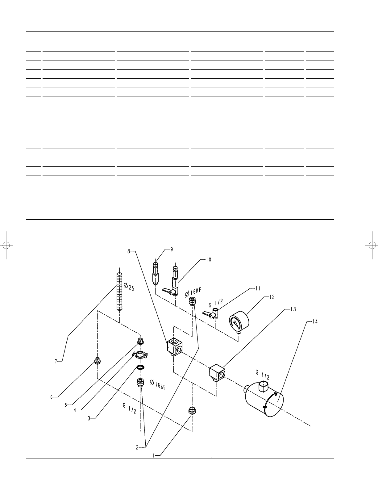
Der exzentrisch im Pumpengehäuse (7/6)
angeordnete Rotor (7/3) unterteilt mit drei
Schiebern (7/4) den Schöpfraum in mehrere
Kammern. Das Volumen jeder Kammer ändert
sich periodisch mit der Drehung des Rotors.
Durch Vergrößerung des zum Ansaugstutzen
(8/A) hin offenen Teil des Schöpfraumes wird Gas
angesaugt. Das Gas passiert das
Schmutzfangsieb und das geöffnete
Saugstutzenventil und gelangt in den
Schöpfraum. Durch den sich weiterdrehenden
Rotor trennt der Schieber einen Teil des
Schöpfraumes vom Ansaugstutzen ab. Dieser Teil
des Schöpfraumes wird verkleinert und das Gas
wird komprimiert, Dann wird das Gas am
Auspuffventil (7/7-8) aus dem Schöpfraum
ausgestoßen.
In den Schöpfraum eingespritztes Öl dient zur
Dichtung, Schmierung und Kühlung.
Das mit dem komprimierten Gas mitgerissene
Öl wird durch Umlenkung im Ölkasten grob
abgeschieden. Anschließend erfolgt eine Fein-
abscheidung in dem integrierten Auspuff-
Filterelement (8/52). Der Ölanteil im Abgas
wird damit unter die Sichtbarkeitsgrenze
gesenkt (Abscheidegrad über 99 %).
Das im Auspuff-Filter abgeschiedene Öl wird
dem Ölkreislauf am Saugstutzen wieder
zugeführt. Die Ölrückführung wird durch ein
Schwimmerventil (8/55) gesteuert.
Öl aus dem Ölvorrat (8/67) wird durch Bohrungen
in den Endlagerdeckeln direkt, sowie über die
Lagerstellen in die Pumpe eingespritzt. Der
Öltransport wird durch den Druckunterschied
innerhalb der Pumpe aufrechterhalten.
Durch Öffnen des Gasballastventils (8/62) kann eine
dosierte Menge Luft - genannt Gasballast - in den
Schöpfraum eingelassen werden. Durch diesen
Gasballast kann (bis zu der in den technischen Daten
angegebenen Grenze der Dampfverträglichkeit) beim
Abpumpen kondensierbarer Gase oder Dämpfe
Kondensation verhindert werden.
Ein unbeabsichtigtes Belüften des
Vakuumbehälters und Ölrücksteigen beim
Abschalten der Pumpe wird durch das
eingebaute Saugstutzenventil (8/64) verhindert.
Beim Abschalten der Pumpe wird der
Schöpfraum über eine Bohrung im Auspuffventil
mit Gas aus dem Ölkasten belüftet. Da dann der
Druck im Innenteil der Pumpe höher ist als in der
Ansaugleitung, schließt das Saugstutzenventil.
Das in den Schöpfraum einströmende Gas
verhindert außerdem, daß bei Stillstand der
Pumpe Öl in den Schöpfraum fließt.
Ein unter der Motorhaube eingebauter Lüfter erzeugt
den zur Kühlung der Pumpe nötigen Luftstrom.
Operating instructions
1 Description
1.1 Design and function
The SOGEVAC SV 16 and SV 25 are single-
stage, oil-sealed rotary vane pumps.
The anti-suckback valve, gas ballast valve and
an exhaust filter, oil return circuit are integrated
functional elements of the SOGEVAC. The
pump is driven by a motor directly integrated
into the housing.
The rotor (7/3), mounted eccentrically in the
pump cylinder (7/6), has three vanes (7/4)
which divide the pump chamber into several
compartments. The volume of each changes
periodically with the rotation of the rotor.
As the rotor rotates, the intake portion of the
pumping chamber expands and sucks in gas
through the intake port (8/A). The gas passes
through the dirt trap and the open anti-
suckback valve and enters the pump chamber.
As the rotor rotates further, the vane separates
part of the pump chamber from the intake port.
This part of the pump chamber is reduced, and
the gas is compressed, then the gas is
expelled from the chamber via the exhaust
valve (7/7-8).
Oil injected into the pump chamber serves to
seal, lubricate and cool the pump.
The oil entrained with the compressed gas is
coarsely trapped in the bottom part of the oil
case. Then fine filtering occurs in the integrated
exhaust filter elements (8/52). The proportion of
oil in the exhaust gas is thus reduced below the
visibility threshold (over 99 % entrapment rate).
The oil trapped in the exhaust filters is returned
to the oil cycle at the anti-suckback valve. The
oil return is controlled by a float valve (8/55).
Oil from the oil reservoir (8/67) is injected
directly, so as over the end flange bearings via
bores in these end flanges in the pump.The oil
flow is ensured by the difference of pressures
within the pump.
By opening the gas ballast valve (8/62), a
dosed quantity or air - so-called "gas ballast" -
is admitted into the pump chamber. This gas
ballast prevents condensation (up to the vapor
tolerance specified in the Technical Data)
when pumping condensable gases or vapors.
Unintentional venting of the vacuum chamber
as well as oil suckback when switching the
pump off are prevented by the built-in anti-
suckback valve (8/64).
When the pump is switched off, the pump
chamber is vented with gas from the oil pump
via a bore in the exhaust valve. Since a
pressure in the inner pump section is then
higher than in the intake line, the anti-suckback
valve close. The gas flowing into the pump
chamber also prevents oil from entering the
chamber when the pump is idle.
A fan attached to motor generates the air flow
needed to cool the pump.
Mode d'emploi
1 Description
1.1 Présentation et principe
Les pompes SOGEVAC SV 16 et SV 25 sont
des pompes à vide à palettes mono-étagées à
joint d'huile.
Le clapet d'aspiration, le robinet de lest d'air et
un filtre anti-aérosol d'échappement, et circuit
de retour d'huile sont des éléments
fonctionnels intégrés dans la pompe. La
pompe est entraînée directement par un
moteur intégré dans le carter.
Le rotor (7/3) monté excentré dans le stator de
la pompe (7/6) sépare la chambre d'admission
de la pompe en plusieurs chambres par
l'intermédiaire de trois palettes (7/4). Le
mouvement du rotor provoque ainsi une
variation cyclique du volume de chaque
chambre.
Par l'augmentation du volume, ouvert du côté
aspiration (8/A), il y a aspiration de gaz. Ce
gaz passe par le tamis autour du clapet
d'aspiration et rentre dans la chambre
d'aspiration. La rotation du rotor fait qu'une
palette isole une partie du volume aspiré, de
l'orifice d'aspiration. Ce volume diminue et le
gaz est comprimé, puis le gaz est refoulé à
travers le clapet d'échappement (7/7-8) hors
de la chambre de compression.
L'huile injectée dans la chambre d'aspiration
sert à l'étanchéité, à la lubrification et au
refroidissement.
Dû au changement de direction du gaz dans le
carter, il y a une séparation grossière d'huile
contenue dans les gaz refoulés puis une
séparation fine à travers le filtre
d'échappement anti-aérosol (8/52). La quantité
d'huile contenue est ainsi descendue en
dessous de la limite de visibilité (séparation
supérieure à 99%).
L'huile récupérée retourne de nouveau dans le
circuit, vers la chambre d'aspiration à travers
une soupape à flotteur (8/55).
L'huile provenant du carter d'huile (8/67) est
aspirée à travers des perçages dans les
flasques, et injectée via les paliers, dans la
pompe. La circulation d'huile est assurée au
moyen de la différence des pressions régnant
entre l'intérieur du stator et le carter.
Par ouverture du robinet de lest d'air (8/62)
une quantité dosée d'air, appelée lest d'air, est
admise dans la chambre de la pompe. Ce lest
d'air permet (dans la limite des spécifications
techniques des vapeurs données), le pompage
des vapeurs condensables en évitant leur
condensation.
Le retour accidentel d'huile, dans l'enceinte par
arrêt de la pompe n'est pas poss ble grâce au
clapet anti-retour d'aspiration (8/64). Grâce à
un petit orifice percé dans le clapet de
refoulement, l'arrêt de la pompe entraîne
aussitôt, sa mise à l'atmosphère.
Un ventilateur monté sous le capot génère le
courant d'air nécessaire au refroidissement de
la pompe.
5

6
1.1.1 Einsatzbereich
SOGEVAC Vakuumpumpen sind vorgesehen
für das Abpumpen von inerten Gasen im
Bereich zwischen Atmosphärendruck und
Enddruck der Pumpen.
Vorsicht
Die SOGEVAC Pumpen sind nicht
geeignet zum Abpumpen von
aggressiven, ätzenden, brennbaren und/oder
explosiven Gasgemischen
Sollten diese Gasgemische vorhanden sein, so
nehmen Sie bitte mit LEYBOLD Kontakt Auf.
Die SOGEVAC Pumpen dürfen nicht in
explosionsgefährdeter und/oder brennbarer
Umgebung betrieben werden.
Im Zweifelsfall nehmen Sie bitte mit LEYBOLD
Kontakt auf.
Achtung
Die Pumpen sind nicht geeignet, Flüssigkeiten
oder mit Staub belade Medien zu pumpen. Es
sind entsprechende Schutzvorrichtungen
vorzusehen.
In Zweifelsfall nehmen Sie bitte mit LEYBOLD
Kontakt auf.
Vor dem Abpumpen von Sauerstoff (oder
anderen hochreactiven Gasen) in Konzentration
größer als Atmosphärenkonzentration
(> 20 %
für Sauerstoff), ist es notwendig eine
Spezialpumpe zu benutzen. Diese muß
modifiziert, entfettet sein, und ein inertes
Spezialöl (wie PFPE Öl) muß verwendet
werden.
Entsprechende Vorsichtsmaßnahmen
treffen.
Bitte kontaktieren Sie Leybold für
Sicherheitshinweise.
.
1.2 Lieferumfang
Die Pumpen mit Drehstrommotor werden mit
ca. 2 m Anschlußleitung ausgeliefert. Bei
Pumpen mit Wechselstrommotor wird ein
passender Stecker beigelegt.
Die für die Erstbefüllung notwendige Ölmenge
ist beigestellt.
Der Ansaugstutzen ist mit einer Schutzkappe
verschlossen. Nach Abziehen des
Schutzplättchen ist in dem Auspuffstutzen der
Auspuffstopfen einzuschrauben. Dieser
Stopfen (8/58) wird separat mitgeliefert.
Die Stabilität der Pumpe ist mit LEYBOLD
Zubehör gewährleistet.
Sollte anderes Zubehör montiert werden, ist
dann der Benutzer verantwortlich für die
Stabilität der Pumpe.
Bitte geben Sie bei der Bestellung von
Ersatzteilen immer die Fabrikations- und
Katalog-Nummer der Pumpe an.
1.1.1 Application range
SOGEVAC pumps are designed for pumping
of inert gases in the range of rough vacuum,
between atmospheric pressure and end
pressure of the pump.
Warning
SOGEVAC pumps are not designed
for pumping of agressive, corrosive,
flammable or explosive gases.
By presence of agressive, corrosive,
flammable or explosive gases, contact
LEYBOLD.
These pumps are not designed for working in
flammable or explosive environment.
In case of doubt, contact LEYBOLD.
Caution
The pumps are not suitable for pumping liquids
or media which contain dust. Corresponding
protective measures must be introduced.
In case of doubt, contact LEYBOLD.
Before Pumping greater than atmospheric
concentrations of oxygen (> 20 %) or other
highly reactive gases, the pump must be
modified, degreased and a special oil (such as
PFPE) must be used
Take adequate safety precautions.
Contact Leybold for important safety
instructions.
1.2 Standard Specification
The pumps with three-phase motors are
supplied with connecting lead approx. 2 m.
(6Ft) long. A suitable plug is provided for
pumps with single-phase AC motor.
The amount of oil needed for the first filling is
supplied.
The intake port is blanked off by a protective
cap. After having ripped off the protective
sticker, the exhaust plug is to be screwed into
the exhaust port. That plug (8/58) is supplied
loose with the pump.
Stability of pump is insured with accessories of
LEYBOLD; mounting of any other accessory
will engage the responsability of user
concerning stability of pump.
When ordering spare parts, please always
state the serial and catalog numbers of the
pump.
1.1.1 Domaine d'utilisation
Les pompes à vide SOGEVAC sont utilisables
dans toute la plage de vide entre la pression
atmosphèrique et la pression limite de la
pompe, et sont destinées au pompage de gaz
inertes.
Avertissement
Ces pompes ne sont pas adaptées
au pompage de matières agressives,
corrosives, inflammables ou explos bles.
En cas de présence dans le gaz pompé de gaz
agressifs, corrossifs, inflammables ou
explosibles, consulter LEYBOLD.
Ces pompes ne sont pas adaptées au travail
en zône inflammable ou explosible.
En cas de doute, consulter LEYBOLD.
Prudence
Les pompes ne conviennent pas pour pomper
des liquides ou des gaz chargés de
poussières. Prendre les mesures de
précaution qui s'imposent.
En cas de doute, consulter LEYBOLD.
Avant de pomper de l’oxygène dans des
concentrations supérieures à la concentration
atmosphérique (> 20 %) ou d’autres gaz
hautement réactifs, il convient d’utiliser une
pompe spéciale. Celle-ci doit être modifiée,
dégraissée et une huile inerte (type PFPE) doit
être utilisée.
Prendre les mesures de sécurités
adéquates.
Contacter Leybold pour les instructions de
sécurité.
1.2 Equipement standard
Les pompes équipées d'un moteur triphasé
sont livrées avec un cable de raccordement
d'env. 2 mètres. Les pompes avec moteurs
monophasés sont livrées avec une prise
intégrée dans le capot et une fiche libre.
La quantité d'huile nécessaire au remplissage
d'origine accompagne la pompe.
L'orifice d'aspiration est bouché par un
capuchon. Après avoir arraché la pastille de
protection, il y a lieu de visser le bouchon
reniflard dans l'orifice de refoulement. Ce
bouchon (8/58) est livré séparément avec la
pompe.
La stabilité de la pompe est assurée avec les
accessoires LEYBOLD. Le montage de tout
autre accessoire engage la responsabilité de
l'utilisateur quant à la stabilité de la pompe.
Lors de la commande de pièces de
rechange, veuillez toujours indiquer les N°
de fabrication (N° de série) et N° de
catalogue.

Kat.-Nr/Ref./Réf.
SV16 SV25
109 00 109 02
109 01 109 03
955 30 955 32
955 01 955 03
Pompe à moteur monophasé
230 V - 50 Hz
Pompe avec moteur triphasé asynchrone
230 V / 400 V, 50 Hz
Pompe avec moteur monophasé
100 V - 50 Hz
Pompe avec moteur triphasé
200 V - 50 Hz / 60 Hz
Pump with single-phase motor
230 V - 50 Hz
Pump with three-phase-motor
230 V / 400 V, 50 Hz
Pump with single-phase motor
100 V - 50 Hz
Pump with three-phase motor
200 V - 50 Hz / 60 Hz
Pumpe mit Wechselstrommotor
230 V - 50 Hz
Pumpe mit Drehstrommotor
230 V / 400 V, 50 Hz
Pumpe mit Wechselstrommotor
100 V - 50 Hz
Pumpe mit Drehstrommotor
200 V - 50 Hz / 60 Hz
7
Bestell-Informationen Kat.-Nr. Ordering data Ref. No. Informations commandes Réf.
1.3 Technische Daten 1.3 Technical Data 1.3 Caractéristiques techniques
SV16 SV25
Nennsaugvermögen 1) Nominal speed 1) Débit nominal 1) m3. h -1 16 25
Saugvermögen 1) Pumping speed 1) Débit d'aspiration 1) m3. h -1 14,5 22,5
Endpartialdruck ohne Ultimate partial pressure Pression partielle finale mbar < 0,5 < 0,5
Gasballast 1) without gas ballast 1) sans lest d'air 1)
Endtotaldruck mit Ultimate total pressure Pression totale finale mbar < 1,5 < 1,5
Gasballast 1) with gas ballast 1) avec lest d'air 1)
Wasserdampfverträglichkeit Water vapor tolerance
Pression admiss ble vapeur d'eau 4)
mbar 40 40
Max. Wasserdampfdurchsatz Max. water vapor throughput Capacité max. d'absorption de kg. h -1 0,3 0,45
mit Gasballast with gas ballast vapeur d'eau avec lest d'air 4)
Anschlüsse, Gewinde Connections, thread Raccordements, filetage G1/2 G1/2
Gewicht Weight Poids kg 23 24
Ölfüllung Oil capacity Quantité d'huile l 1,8 1,8
Motorleistung Motor power Puissance moteur kW 0,55 0,75
Nenndrehzahl Rated speed Vitesse de rotation nominale min -1 1500 1500
Gemittelter Schalldruck- Noise level 2) Niveau de bruit 2) dB (A) 59 59
pegel 2)
1) nach D N 28 400 ff - to DIN 28400 and following numbers - selon DIN 28400 et les numéros suivants
2) Bei Enddruckbetrieb ohne Gasballast, Freifeldmessung in 1 m Abstand - operated at the ultime pressure without gas ballast, free-field measurement at a distance of 1 m - à pression limite sans lest
d'air, mesures en plein air à une distance de 1 m
4) Bei Umgebungstemperatur 20° bis 25 °C, with room temperature 20 to 25 °C, temperature ambiante entre 20 et 25 °C.

8
Fig 2a Saugvermögenskurven
Pumping speed
Courbes de capacité d'aspiration
ohne Gasballast
without gas ballast
sans lest d'air
Druck / pressure / pression
bei / at / à 50 Hz
Saugvermögen / pumping speed / débit
mit Gasballast
with gas ballast
avec lest d'air
1.3.1 USA - Versionen 1.3.1 US versions 1.3.1 Versions US
Umwandlung der Einheiten Conversion of Units
Conversion mm - inch, see Fig. 1
Conversion des unités
Conversion factors Different pressure units Different pumping speed units
Mbar torr inches Hg m3.h-1 I.s-1 cfm
(millibar) vacuum
1lb = 0.453 kg 1013 760 0 m3. h-1 = m3/h 1 0.278 0.589
1 qt = 0.946 l 400 300 18.12
1 hp = 0.735 kW 133 100 25.98 I.s-1 = I/s 3.60 1 2.12
1 r.p.m. = 1 min -1 4 3 29.80
1 inch = 25.4 mm 1 0.75 29.89 cfm (cubic feet 1.699 0.472 1
0 0 29.92 per minute)
1 atm (atmosphere) = 1013 mbar Example : 1 m3.H-1 = 0.589 cfm
1 Pa (pascal) = 0.01 mbar = 10-2 mbar Note : The nominal pumping speed of
1 bar = 1000 mbar a pump at 60 Hz is 20% higher than at 50 Hz
1 torr = 1.33 mbar
mm 20 32 36 115 190 196 198 216 218 250 263 415
inch 25/32 11/4 17/16 417/32 71/2 723/32 713/16 81/2 819/32 927/32 103/8 1611/32
m3h-1
mbar
Fig 1 Maßzeichnung der SV16 und SV25
Dimensional drawing of SV16 and SV25
Plan d'encombrement SV16 et SV25
OPTION / ON REQUEST : 710 42 890
1 Lueftung / ventilation / Grille de ventilateur
2 Elektrischer Anschluss / Electrical connection / Connection électrique
3 Platz fuer montage des Auspuff-filters / Space for mounting exhaust filter /
Espace pour montage filtre d’échappement
Option 712 34 720
Wasserkuehlung
Water cooling
Refroidissement par eau Ø 8
Wasser eintritt
Water inlet
Entrée d’eau
Wasser austritt
Water outlet
Sortie d’eau
Transportlasche
Lifting lug
Anneau de levage
Option : 710 42 890

Kat.-Nr/Ref./Réf.
SV16 SV25
109 81 109 91
109 82 109 92
109 80 109 90
Pumpe mit Wechselstrommotor
115 VAC, 60 Hz
Pumpe mit Wechselstrommotor
230 VAC, 60 Hz
Pumpe mit Drehstrommotor
208/230/460 VAC, 60 Hz
9
Fig 2b Saugvermögenskurven
Pumping speed (volume flow rate)
Courbes de débit
ohne Gasballast
without gas ballast
sans lest d'air
Druck / pressure / pression
bei / at / à 60 Hz
Saugvermögen / pumping speed / débit
mit Gasballast
with gas ballast
avec lest d'air
Pompe à moteur monophasé
115 VAC, 60 Hz
Pompe avec moteur monophasé
230 VAC, 60 Hz
Pompe avec moteur triphasé
208/230/460 VAC, 60 Hz
Bestell-Informationen Ordering data Informations commandes
Pump with single-phase motor
115 VAC, 60 Hz
Pump with single-phase motor
230 VAC, 60 Hz
Pump with three-phase motor
208/230/460 VAC, 60 Hz
SV 16 SV 25
Nennsaugvermögen Nominal pumping speed Débit nominal cfm 11 17
Saugvermögen Pumping speed Débit d'aspiration cfm 10 15
Endpartialdruck ohne Ultimate partial pressure Pression partielle finale Torr ≤0.4 ≤0.4
Gasballast without gas ballast sans lest d'air
Endtotaldruck mit Ultimate total pressure Pression totale finale Torr ≤1.15 ≤1.15
Gasballast with gas ballast avec lest d'air
Wasserdampfverträglichkeit Water vapor tolerance
Pression admissible vapeur d'eau
Torr 30 30
in Hg 28.7 28.7
Max. Wasserdampfdurchsatz Water vapor pumping Capacité max. d'absorption de lbs.hr 0.7 1.2
mit Gasballast with gas ballast vapeur d'eau avec lest d'air
Anschlüsse NPT Connections ports, NPT (F) Raccordements NPT 1/2 1/2
Gewicht Weight Poids lbs 51 53
Ölfüllung Oil filling Quantité d'huile qt 2 2
Motorleistung Motor power Puissance moteur hp 1 11/2
Nenndrehzahl Rated speed Vitesse de rotation nominale r.p.m. 1800 1800
Gemittelter Schalldruck- Noise level to Niveau de bruit selon dB (A) 59 59
pegel nach DIN 45 635 DIN 45 635 DIN 45 635
m3. h-1
mbar

10
1.4 Zubehör 1.4 Accessories 1.4 Accessoires
Pos. Bezeichnung Designation Désignation Anschlüsse Best.-Nr.
Item Connections Ref. No
N° Raccordements Réf.
1 Verbindungsstück ( dreiteilig)* Connecting piece (three piece)* Raccord en 3 parties* G1/2 **711 18 020
2 Schraubnippel* Screw-in nipple* Adapteur* G1/2-DN 16 KF **711 18 120
3 Zentrierring Centering ring Anneau de centrage DN 16 KF 183 26
4 Spannring Clamping ring Collier de serrage DN 16 KF 183 41
5 Schlauchanschluß Hose connection Raccord pour tuyau DN 16 KF-25 mm **711 18 300
6 Schlauchanschluß* Hose connection* Raccord pour tuyau G1/2- 25 mm **711 18 011
7 PVC-Schlauch PVC hose Tuyau PVC 25mm **711 18 323
8 T-Stück T-piece Té G1/2 **711 18 250
9 Vakuumregelventil Vacuum control valve Soupape de réglage G1/2 951 86
10 Vakuumregelventil mit Vacuum control valve with Soupape de réglage avec vanne
Absperrventil shut-off valve d'isolement G1/2 **951 87
11 Kugelhahn Ball valve Robinet à boisseau sphérique G1/2 **711 30 113
12 Feder-Vakuummeter Spring vacuum meter Vacuomètre G1/2 **951 92
13 Rohrbogen 90° Ebow 90° Coude 90° G1/2 **711 18 210
14 Staubfilter F 16/25 Dust filter F 16/25 Filtre dépoussièreur F 16/25
mit Papierpatrone with paper cartridge avec filtre papier G1/2 951 50
Ersatzpatrone (Papier) Spare cartridge (paper) Cartouche de rechange (papier) 710 40 762
mit Metallpatrone with metal cartridge avec cartouche métal 711 27 093
Ersatzpatrone (Metall) Spare cartridge (metal) Cartouche de rechange (métal) 710 65 813
mit Aktivkohlepatrone with active-charcoal cartridge avec cartouche charbon actif 711 27 092
Ersatzpatrone (Aktivkohle) Spare cartridge (active-charcoal) Cartouche de rechange (charbon actif)
710 65 713
* mit NBR-O-Ring / with NBR O-Ring / avec joint torique en NBR
** Not stocked by LEYBOLD USA. Contact factory
Abscheider SL 2 Separator SL 2 Séparateur SL 16-25 951 38
Fig. 3 Zubehör
Accessories
Accessoires

11
1.5 Schmiermittel
Ausser besonderem Hinweis auf der Pumpe,
empfehlen wir die Sogevac Pumpen mit Leybold
GS32 oder einem den Spezifikationen
entsprechendem Öl zu betrieben. GS32 ist
Vakuumpumpenöl, das vielen Ansprüchen
gerecht wird :
- Niedriger Dampfdruck, auch bei hohen Tem-
peraturen ;
- flache Viskositätskurve ;
- Wassergehalt und Wasseraufnahme minimal ;
- gute Schmiereigenschaften ;
- beständig gegen Alterung bei mechanischer
Beanspruchung.
Bei Verwendung anderer Markenöle schwach
legierte Mineralöle der Viskositätsklasse ISO
VG 32, 46 oder 68 einsetzen.
Eine Benutzung mit anderen Spezialschmier-
mitteln für besondere Anwendungsfälle ist
möglich.
Bitte LEYBOLD kontaktieren.
Benutzen Sie ausschl. von LEYBOLD
qualifizierte Betriebsmittel.
Pumpenöl GS32 Kat. Nr.
2 l 711 17 723
5 l 711 17 724
60 l 711 17 727
1.6 Handhabung und Lagerung
Achtung
Pumpen, die mit Betriebsmittel befüllt sind, nur
in gerader Position transportieren (horizontale).
Der Neigungswinkel darf max. 10° nicht
üsbersteigen. Sonst kann es zu Ölaustritt
kommen. Vermeiden Sie andere
Transportlagen.
Vorsicht
Prüfen Sie die Pumpe auf Ölleckage,
es besteht Sturzgefahr auf Öllache.
Benutzen Sie zum Heben der Pumpen nur die
dafür vorgesehenen Transportöse, bzw.
vorgeschriebene Hebevorrichtungen.
Achten Sie darauf, daß diese sicher installiert
sind. Benutzen Sie geeignete Hebezeuge.
Halten Sie alle Sicherheitsvorschriften ein.
Achtung
Lagern Sie die Pumpe bis zur erneuten
Verwendung trocken, vorzugsweise bei
Raumtemperatur (20 °C). Vor Einlagerung ist
die Pumpe ordnungsgemäß von der
Vakuumanlage zu trennen, mit trockenem
Stickstoff zu spülen und ein Ölwechsel
vorzunehmen. Die Ein- und Auslaßöffnungen
der Pumpe sind mit dem zum Lieferumfang
gehörenden Transportverschlüssen zu
versehen. Gasballast muß geschlossen sein,
ggf. ist die Pumpe für längere Lagerdauer in
einem PE-Beutel mit beigefügtem
Trockenmittel (Silicagel) einzuschweißen.
Bei einer Lagerdauer von über einem Jahr ist
vor Wiederinbetriebnahme eine Wartung sowie
ein Ölwechsel durchzuführen. Wir empfehlen,
sich an den Leybold-Service zu wenden.
1.5 Lubricants
Except differently specified on the pump, we
recommend to run the Sogevac pumps with
GS32 from Leybold (HE 100) or an equivalent oil
which meets following requirements :
- low vapor pressure, when at high temperatures;
- flat viscosity curve ;
- minimum water content and absorption ;
- good lubricating properties ; and
- resistant to aging under mechanical strain.
When using other oil brands, employ low-
doped, non detergent mineral oils of viscosity
class ISO VG 32, 46 or 68.
Using the other special-grade lubricants for
specific applications is possible.
Please consult LEYBOLD.
Only use lubricants which have been fully
qualified by LEYBOLD.
Pump oil GS32 Ref. No.
2 liters 711 17 723
5 liters 711 17 724
60 liters 711 17 727
Pump oil HE100 (US) Cat. No.
1 gallon 898 538
55 gallons 898 539
1.6 Manipulation and stock
Caution
Pumps which have been filled with operating
agent must only be moved in the upright
position (horizontally). The angle of slope may
not be over 10° max. Otherwise oil may
escape. Avoid any other orientations while
moving the pump.
Warning
Check the pump for the presence of
any oil leaks, because there is the
danger that someone may slip on the oil which
has leaked from the pump.
Only use the lifting lugs which are provided on
the pump to lift the pump with the specified
lifting devices.
Make sure that these have been installed
safety. Use suitable lifting equipment. Make
sure that all safety regulations are observed.
Caution
Until the pump is put back in to service once
more, the pump should be stored in a dry place,
preferably at room temperature (20 °C). Before
taking the pump out of service, it should be
properly disconnected from the vacuum system,
purged with dry nitrogen and the oil should be
exchange too. The inlet and exhaust ports of
the pump must be blanked off using the
shipping seals which are included upon delivery
of the pump. The gas ballast must be closed
and if the pump is to be shelved for a longer
period of time it should be sealed in a plastic
bag together with a desiccant (Silicagel).
If the pump has been shelved for over one
year, standard maintenance must be run and
the oil must be exchanged too before the pump
is put in to service once more. We recommend
that you contact the service from LEYBOLD.
1.5 Lubrifiants
Sauf indication particulière figurant sur la
pompe, nous recommandons d'utiliser l'huile
Leybold GS32 ou une huile équivalente. L'huile
GS32 est un type d'huile pour pompes à vide
répondant à beaucoup d'exigences :
- basse pression de vapeur même à hautes
températures ;
- courbe de viscosité plate ;
- contenance et absorption d'eau minimum ;
- bonnes qualités de lubrification ;
- résistance contre le vieillissement aux
contraintes
mécaniques.
- résistance à l'oxydation
Pour le choix d'autres huiles du marché,
utiliser des huiles minérales de la classe de
viscosité ISO VG 32, 46 ou 68.
Une utilisation d'autres lubrifiants pour des cas
spéciaux est possible.
Contacter LEYBOLD.
Seuls les lubrifiants recommandés par
LEYBOLD peuvent être utilisés.
Huile GS32 N° cat.
2 l 711 17 723
5 l 711 17 724
60 l 711 17 727
1.6 Manipulation et stockage
Prudence
Les pompes avec le plein de lubrifiant doivent
être transportées en position horizontale pour
éviter la perte d'huile. L'angle d'inclinaison ne
doit pas dépasser 10° maxi. Eviter toute autre
position pendant le transport.
Avertissement
Détecter les éventuelles fuites d'huile.
Il y a un risque de chute sur les
flaques d'huile.
Pour soulever la pompe, il faut utiliser les
anneaux de levage prévus à cet effet, ou les
dispositifs de manutention prescrits.
Veillez à bien installer les dispositifs de
manutention. Utilisez vos propres engins de
levage. Respectez toutes les prescriptions de
sécurité.
Prudence
Stocker les pompes inutilisées dans un endroit
sec, de préférence à la température ambiante
(20 °C). Auparavant, il faudra séparer
correctement la pompe de l'installation à vide,
la rincer à l'azote sec et renouveler l'huile.
Fermer les orifices d'aspiration et de
refoulement de la pompe avec les capuchons
de l'équipement fourni. Le lest d'air doit être
fermé. Si nécessaire, et pour un stockage de
longue durée, il faudra emballer la pompe dans
un emballage plastique soudé, rempli de
dessiccateur (Silicagel).
Après un stockage de plus d'un an, il faudra
faire une révision et un renouvellement de
l'huile avant de remettre la pompe en service.
Nous recommandons de faire appel au S.A.V.
de LEYBOLD.

12
2 Bedienung und Betrieb
Die Standardpumpe ist nicht zur Aufstellung in
Ex-zonen geeignet. Wir bitten um
Rücksprache, sofern Sie einen solchen Einsatz
vorsehen. Vor Installation ist die Pumpe
spannungsfrei zu schalten und gegen
unbeabsichtiges Einschalten zu sichern. Zur
Installation nur geschultes Fachpersonal
einsetzen.
Beachten Sie alle Sicherheitsvorschriften.
2.1 Aufstellen
Die Einhaltung der Reihenfolge der
hier beschriebenen Arbeitsschritte ist
für eine sicherheitsgerechte und
funktionssichere Inbetriebnahme unbedingt
erforderlich.
Die Inbetriebnahme darf nur von geschultem
Fachpersonal durchgeführt werden.
Die Pumpe kann auf jeder ebenen
waagerechten Fläche auf ihren Gummifüßen
aufgestellt werden.
Unter der Pumpe befinden sich Gewindelöcher
M6 zur Befestigung der Pumpe oder zum
Einschrauben von Schwingungsdämpfern
(Option).
Achtung
An einer geneigt aufgestellten Pumpe kann der
Ölstand nicht mehr korrekt abgelesen werden.
Es besteht die Gefahr, daß kein Öl mehr
angesaugt wird, obwohl das Ölschauglas noch
bedeckt ist.
Die Umgebungstemperatur der Pumpe soll
zwischen 12°C und 40°C liegen. Durch Modi-
f kation der Pumpe oder Änderung der Ölsorte
ist der Betrieb bei höherer oder niedrigerer
Umgebungstemperatur möglich. Dazu erbitten
wir Ihre Anfrage.
Um ausreichende Kühlung der Pumpe zu
gewährleisten, neben den Luftansaugflächen
und -ablaßflächen Platz lassen (siehe Abb. 1).
Achten Sie darauf, die Luftansaugöffnungen
am Motor sauberzuhalten.
Achtung
Der Hauptluftstrom zur Kühlung der Pumpe
verläuft zwischen der Pumpe und dem
Bodenblech (8/69). Deshalb muß das Blech
bei Betrieb immer an der Pumpe montiert
bleben. Die Luft-Einlaßöffnungen und - Auslaß-
öffnungen dürfen nicht blockiert werden.
Hinweis
Die SOGEVAC SV 16/25 können auf Bestel-
lung mit einer zusätzlichen Wasserkühlung
ausgeliefert werden (Anschluß : Wasserrohr
Außendurchmesser 8 mm).
Hinweis
Für die SV 16/25 ist ein Ölstand-Kontroll-
schalter lieferbar. Zwecks Anpassung ist ein
spezielles Ölschauglas auf die Pumpe montiert ;
oder mitgeliefert (8/79).
2 Operation
The standard pump is not suitable for
installation in explosion hazard areas. Please
contact us, when you are planning such an
application. Before installing the pump you
must reliably disconnect it from the electrical
power supply and prevent the pump from
running up inadvertently. The pump must only
be installed by suitably qualified and trained
personnel.
Observe all safety regulations.
2.1 Installation
It is essential to observe the following
instructions step by step to ensure a
safe start-up.
Start-up may only be conducted by trained
specialists.
The pump can be set up on any flat, horizontal
surface on its rubber supports.
Under the pump are threaded bores M6 for
securing the pump or screwing in vibration
absorbers (extras).
Caution
The oil level cannot be read properly if the
pump is tilted. The may lead to insufficient
being sucked in even though the oil level glass
is still covered.
The pump's ambient temperature should be
between 12°C (55°F) and 40°C (104°F). By
modifying the pump or changing the oil type,
the pump can be run at a higher or lower
ambient temperature. Please consult us about
this.
To ensure adequate cooling of the pump; leave
space at the air intake and exhaust points (see
Fig. 1). Also ensure that there is enough space
for changing the exhaust filter (see Fig. 1).
Make sure to keep the air intake of the motor
clean.
Caution
The main air flow for cooling the pump passes
between the pump and the baseplate (8/69).
During operation the baseplate must thus
always be attached to the pump. The air inlets
and outlets must not be obstructed.
Note
On request the SOGEVAC SV 16/25 pumps
can be supplied with an additional water cooler
(connection : water pipe outer diameter 8 mm).
Note
An alectrical oil level switch is available for SV
16/25. A special oil sight glass is then fitted on
the pump, or supplied with the device, for
adaptation (8/79).
2 Installation
La pompe standard ne convient pas pour
l'installation dans des zones à risque
d'explosion. Nous vous prions de nous
consulter si vous prévoyez une telle
application. Couper l'alimentation secteur,
avant d'installer la pompe et interdire
efficacement les remises en circuit
involontaires. L'installation doit être réservée
aux spécialistes expérimentés.
Respecter toutes les prescriptions de
sécurités.
2.1 Mise en place
Il est impératif de suivre pas à pas les
recommandations suivantes pour
assurer un démarrage correct de la
pompe.
Le démarrage doit être réalisé uniquement par
un personnel qualifié.
La pompe peut être installée sur tout plan
horizontal sur ses pieds en caoutchouc.
Sous la pompe se trouvent des taraudages M6
pour la fixation de celle-ci ou pour y visser des
amortisseurs de vibrations (option).
Prudence
Le niveau d'huile ne peut pas être lu
correctement sur une pompe installée inclinée.
L'aspiration d'huile risque de manquer.
La température ambiante de la pompe doit se
situer entre 12°C et 40°C. il est possible par
une modification de la pompe ou par un
changement d'huile d'employer la pompe à des
températures plus élevées ou plus basses.
Dans ce cas, veuillez nous consulter.
Pour assurer un refroidissement suffisant, il y a
lieu de dégager les zones d'aspiration et de
refoulement de l'air (voir Fig. 1).
Maintenir la propreté de l'orifice d'aspiration
d'air du moteur.
Prudence
Le flux principal pour le refroidissement de la
pompe circule entre la pompe et la tôle
inférieure (8/69). De ce fait, cette tôle doit
toujours être montée sur la pompe en service.
Les entrées et sorties d'air doivent être
dégagées.
Nota
Sur demande les pompes SOGEVAC SV
16/25 peuvent être livrées avec refroidisseur à
eau supplémentaire (connection : tube d'eau
diamètre extérieur 8 mm).
Nota
Sur demande un détecteur électrique du
niveau d'huile est livrable. Un voyant d'huile
spécial est alors monté sur la pompe ou livré
avec le détecteur, pour adaptation (8/79).

13
2.2 Raccordement à l'installation
La pompe standard ne convient pas pour
l'installation dans des zones à risque
d'explosion. Nous vous prions de nous
consulter si vous prévoyez une telle
application. Couper l'alimentation secteur,
avant d'installer la pompe et interdire
efficacement les remises en circuit
involontaires. L'installation doit être réservée
aux spécialistes expérimentés.
Respecter toutes les prescriptions de
sécurités.
2.2.1 Côté aspiration
Enlever le capuchon de protection (8/A).
La pompe comporte un taraudage de 1/2" pour
le raccordement. On peut, à l'aide des
raccords adéquats (voir fig. 3 et section 1.4)
raccorder la pompe à l'enceinte.
Le passage sur une petite bride est possible.
Le passage sur une petite bride ISO requiert
toujours l'utilisation d'un anneau de serrage
(3/4) et d'un anneau de centrage (3/3) avec le
joint torique correspondant. Sur le raccord Té
peut être connecté un appareil de mesure
(3/11) ou un robinet casse-vide (3/12).
La section de la tuyauterie d'aspiration doit
être au moins égale à la section de l'orifice de
raccordement sur la pompe. Une canalisation
d'aspiration à section trop petite limite le débit
d'aspiration. Nous recommandons de monter
les raccords filetés au Loctite 572 ou 577 ou
au Teflon pour assurer une bonne étanchéité.
Nous recommandons de monter un filtre en
position horizontale. On évite ainsi, lors du
démontage du filtre la chute de particules à
l'intérieur de la pompe.
Pour le pompage des vapeurs, nous
recommandons de monter des séparateurs
côté aspiration et refoulement (voir point 1.4).
Aucune particule solide ou liquide ne
doit pénétrer dans la pompe.
Avertissement
- La pompe doit être reliée à la
canalisation d'aspiration sans
contrainte mécanique. Nous recommandons
de monter une canalisation souple entre la
pompe et l'installation.
- Le choix des materiaux pour le montage des
canalisations doit tenir compte du fluide
pompé, ainsi que son étanchéité.
La pression d'admission max. à la bride
d'aspiration ne doit pas dépasser la pression
atmosphérique (env. 1013 mbar). Ne jamais
faire travailler la pompe avec une surpression
au raccord d'aspiration.
2.2 Connection to system
The standard pump is not suitable for
installation in explosion hazard areas. Please
contact us, when you are planning such an
application. Before installing the pump you
must reliably disconnect it from the electrical
power supply and prevent the pump from
running up inadvertently. The pump must only
be installed by suitably qualified and trained
personnel.
Observe all safety regulations.
2.2.1 Intake Side
Remove the protective cap from the intake
orifice (8/A).
The pump has a 1/2" internally-threaded
connection. Using suitable connecting pieces
(see Fig. 3 and section 1.4), the pump can be
connected to the vacuum system.
Adaptation to a clip-type flange connection is
also possible. For an ISO clip-type flange
connection, a clamping ring (3/4) and a
centering ring (3/3) with associated O-ring are
always needed. You can connect a gauge
(3/11) or a venting valve (3/12) to a T-piece.
The cross-section of the intake line should be
at least the same as that of the intake port. If
the intake line is too narrow, it reduces the
pumping speed. We recommend appyling
LOCTITE®577,515 or 567 Teflon tape to the
screwed unions so that they are vacuum-tight.
It is recommended to install a dust filter
horizontally. This ensures that when removing
the filter no particles fall into the intake port.
For pumping vapors, we recommend that
condensate traps be installed on the intake
and exhaust sides (see Section 1.4).
No particles or liquids may enter in the
pump.
Warning
- Pump should be connected to inlet
line without any tension.
- Use flex lines or pipe unions in your inlet and
exhaust lines so they can be easily removed
for pump maintenance.
- Type of materials used for mounting of
canalisations should take care of pumped
gases. It is the same for its tightness.
The maximum pressure at the inlet may not
exceed atmospheric pressure (about 1013 mbar).
Never operate the pump in the presence of over
pressures at its intake.
2.2 Anschluß an die Anlage
Die Standardpumpe ist nicht zur Aufstellung in
Ex-zonen geeignet. Wir bitten um
Rücksprache, sofern Sie einen solchen Einsatz
vorsehen. Vor Installation ist die Pumpe
spannungsfrei zu schalten und gegen
unbeabsichtiges Einschalten zu sichern. Zur
Installation nur geschultes Fachpersonal
einsetzen.
Beachten Sie alle Sicherheitsvorschriften.
2.2.1 Ansaugseite
Schutzkappe von der Ansaugöffnung (8/A)
entfernen.
Die Pumpe ist zum Anschluß mit einem 1/2"-
Innengewinde ausgerüstet. Mit Hilfe passender
Anschlußstücke (siehe Abb. 3 und Abschnitt
1.4) kann die Pumpe wahlweise an die Anlage
angeschlossen werden.
Auch der Übergang zu einer Kleinflansch-
Verbindung ist möglich. Zu einer Kleinflansch-
Verbindung nach ISO wird immer ein
Spannring (2/4) und ein Zentrierring (3/3) mit
zugehörigem O-Ring benötigt. An das T-Stück
kann ein Meßinstrument (3/11) oder ein
Belüftungsventil (3/12) angeschlossen werden.
Der Querschnitt der Ansaugleitung sollte min-
destens die Größe des Pumpenanschlusses
erreichen. Eine Ansaugleitung mit zu gerin-
gem Querschnitt drosselt das Saugvermögen.
Wir empfehlen, die Schraubverbindungen mit
LOCTITE®572 oder 577 oder mit Teflonband
zu montieren, um ihre Vakuumdichtheit zu
gewährleisten.
Falls im angesaugten Medium Stäube
auftreten, sollte unbedingt ein Staubfilter
eingebaut werden ! (siehe Abschnitt 1.4). Wir
empfehlen, den Staubfilter waagerecht
anzubauen. Damit kann verhindert werden,
daß bei Demontage des Filters abgeschiedene
Partikel in den Ansaugstutzen geraten.
Beim Absaugen von Dämpfen empfehlen wir,
Abscheider auf der Saugseite und auf der
Auspuffseite einzusetzen (siehe Abschnitt 1.4).
Achten Sie darauf, daß sich keine
Fremdkörper oder Flüssigkeiten in
der Vakuumpumpe befinden.
Vorsicht
- Die Saugleitung sollte mit einer
elastischen Rohrverbindung span-
nungsfrei an die Pumpe angeschlossen
werden.
- Ansaugdruck soll in keinem fall Höher als
Atmosphärdruck sein.
- bei der Montage der Saugleitung ist auf die
Richtige Wahl des Werkstoffes zu achten; er
muß dem abzupumpenden Medium
standhalten. Gleiches gilt für die Dichtigkeit.
Der max. Einlaßdruck am Saugtutzen darf
atmosphärendruck (ca. 1013 mbar) nicht
überschreiten. Pumpe nicht mit Überdruck am
Saugstutzen betre ben.

14
2.2.2 Auspuffseite
In den Auspuffstutzen der Pumpe (8/B) ist der
Stopfen (8/58) einzuschrauben. Der Stopfen ist
durchlässig für Auspuffgas und verhindert das
Eindringen von Schmutz in den Auspuff. Er soll
nur weggelassen werden, wenn die Pumpe an
eine Auspuffleitung angeschlossen wird.
Die SOGEVAC SV 16 und SV 25 sind mit
einem integrierten Auspuff-Filter ausgerüstet,
der auch bei hohen Gasdurchsatz den
anfallenden Ölnebel bis zu 99% sicher
abscheidet und ein ölnebelfreies Abgas
garantiert. Bei zugesetzten Auspuff-Filter öffnet
bei 1,5 bar ein Überdruckventil und das Filter
wird überbrückt. Dadurch steigen der Ölanteil
im Abgas und der Ölverbrauch der Pumpe an.
Im Einzelfall ist zu prüfen, ob eine Abgaslei-
tung notwendig und/oder vorgeschrieben ist.
Leichtflüchtige Stoffe können das Filter pas-
sieren. Je nach Beschaffenheit des abzupum-
penden Mediums empfiehlt es sich, zusätzlich
eine Auspuffleitung anzuschließen ; diese ist
immer erforderlich, wenn die Abgase gefährlich
sind.
Vorsicht
Je nach Einsatzart bzw. gefördertem
Medium die entsprechenden
Vorschriften und Merkblätter beachten !
Der Auspuffstutzen der Pumpe ist ebenfalls mit
einem 1/2" - Innengewinde ausgestattet. Eine
Schlauchleitung kann über einen passenden
Einschraubnippel angeschlossen werden
(siehe Abb. 3 Abschnitt 1.4).
Achtung
Der Querschnitt der Auspuffleitung
sollte mindestens so groß sein wie
der des Pumpen-Anschlusses. Eine
Auspuffleitung mit zu geringem Querschnitt
kann zu unzulässigem Überdruck in der
Pumpe führen.
Die Auspuffleitung abfallend verlegen, um
den Rückfluß von Kondensat in die Pumpe zu
verhindern. Falls das nicht möglich ist, emp-
fehlen wir dringend, einen Kondensat-
Abscheider einzubauen.
Werden mehrere Pumpen an einer Auspufflei-
tung angeschlossen, muß diese einen aus-
reichenden Durchmesser haben.
Achtung
- Auf keinen Fall darf die Pumpe mit
abgesperrter oder verengter
Auspuffleitung betrieben werden. Bitte achten
Sie vor der Inbetriebnahme darauf, daß in der
Abluftleitung - falls vorhanden - Steckscheiben
oder ähnliche Absperrorgane geöffnet werden,
und daß die Abluftleitungen nicht durch
Ablagerungen zugesetz sind.
- Bei der Montage der Auspuffleitung ist auf die
richtige Wahl des Werkstoffes zu achten : er
muß dem abzupumpenden Medium
standhalten.
- Bei abpumpen von gefährlichen Medien soll
darauf geachtet werden, daß die
Auspuffleitung dicht ist.
Der max. Auspuffdruck darf 1,15 bar (absolut)
nicht überschreiten. Verhindern Sie im Betrieb
sicher das Blockieren der Auspuffleitung.
AuspuffFilter, Zubehör und Rohrleitungen
müssen für den max. auftretenden Durchsatz
ausgelegt sein. Der max. Durchsatz ist das
Saugvermögen der Pumpe.
2.2.2 Exhaust Side
The plug (8/58) is to be screwed into the
exhaust of the pump (8/B). This plug allows
exhaust gases to pass throught it, while
preventing particles form entering the pump.
The plug should be descarded only if the pump
is connected to an exhaust line.
The SOGEVAC SV 16 and SV 25 have inte-
grated exhaust filters which, even at a high gas
throughput, trap over 99% of oil mist ; and
guarantee exhaust gas free of oil. If the
exhaust filters is clogged, a pressure relief
valve opens at 1.5 bar, absolute (7 psid), and
the filters are bypassed. As a result, the
proportion of oil in the exhaust gas as well as
the pump's oil consumption rise. Installing new
exhaust filters correct this problem (See 3.4).
Check in the individual case whether an
exhaust line is necessary and/or prescribed.
Volatile substances can pass through the filter.
An exhaust line is always necessary if the
exhaust gases are dangerous.
Warning
Depending on the type of use of the
pump and the medium pumped,
please the relevant safety rules and
specifications.
The pump's exhaust likewise has a 1/2"
internal thread. A hose can be connected via a
suitable screw-in nipple (see Fig. 3 and
Section 1.4).
Caution
The cross-section of the exhaust line
should be at least the same as that of
the pump's exhaust port. If the exhaust line is
too narrow, excessive pressure may occur in
the pump.
Install the exhaust line with a downward
slope or a drain leg so as to prevent
condensate from flowing back into the pump. If
this is not possible, we strongly recommend
installing a condensate trap.
If several pumps are connected to one exhaust
line, ensure that it has an adequate diameter.
Warning
- Never operate the pump with a
blocked or restricted exhaust line.
Make sure before start-up that any blinds or
similar shut-off devices in the exhaust line are
opened and that the exhaust line are not
obstructed by deposits.
- type of materials used for mouting
canalisations should be choosen in
consideration of pumped gases.
- By pumping of dangerous gases, exhaust line
must be tight.
The maximum exhaust pressure must not
exceed 1,15 bar (absolute). Also reliably
prevent the occurrence of any blockage in the
exhaust line. Exhaust filter, accessories and
the tubing must be rated according to the
maximum throughput. The maximum
throughput is equivalent to the pumping speed
of the pump.
2.2.2 Côté refoulement
Le bouchon (8/58) perméable aux gaz
d'échappement est à visser dans
l'échappement de la pompe (8/B). Ce bouchon
empêche les impuretés d'entrer dans
l'échappement. Ne l'enlever que dans le cas
où la pompe serait connectée à une conduite
d'échappement.
Les SOGEVAC SV 16 et SV 25 sont équipées
de filtres anti-aérosols d'échappement intégrés
qui même à débit élevé éliminent le brouillard
d'huile jusqu'à 99% et garantissent ainsi un
gaz sans huile. Dans le cas d'un colmatage de
filtre, une soupape montée en by-pass s'ouvre
à 1,5 bar et court-circuite le filtre. De ce fait, la
quantité d'huile dans les gaz d'échappement
s'accroît et, par conséquent, la consommation
d'huile de la pompe augmente.
Il y a lieu de vérifier dans des cas isolés, si une
conduite d'échappement est nécessaire. Des
matières volatiles peuvent traverser le filtre.
Suivant la composition du fluide pompé, il y a
lieu de se raccorder sur une conduite
d'échappement ; celle-ci étant toujours exigée
dans le cas de gaz dangereux.
Avertissement
Selon le type d'utilisation ou le gaz
employé, les consignes et fiches de
spécification correspondantes sont à observer.
L'orifice d'échappement de la pompe est
pourvu d'un taraudage de 1/2". Un tuyau peut
y être connecté à l'aide d'un mamelon (voir fig.
3 et point 1.4).
Prudence
La section de la canalisation
d'échappement doit être au moins
aussi grande que l'orifice de raccordement de la
pompe. Une canalisation avec section trop
faible peut entraîner une pression inadmissible
dans la pompe. Disposer la canalisation
d'échappement en l'inclinant vers le bas
pour éviter le retour des condensats dans la
pompe. Si cette disposition est impossible, il est
fortement conseillé de monter un séparateur de
condensats.
Dans le cas de branchement de plusieurs
pompes sur la canalisation d'échappement
commune, celle-ci devra être prévue avec un
diamètre suffisant.
Avertissement
- Ne faire tourner, en aucun cas, une
pompe avec une canalisation
d'échappement bouchée ou rétrécie.
Veillez, avant la mise en service, que la
canalisation d'échappement (si existante) soit
ouverte, (vannes et autres organes) et qu'elle
soit libre de tout dépôt qui aurait pu s'y
accumuler.
- Le choix des materiaux pour le montage des
canalisations doit tenir compte du fluide
pompé.
- Lors du pompage de gaz dangereux, la
canalisation d'échappement doit être étanche.
La pression d'échappement ne doit pas
dépasser 1,15 bar (absolus). Empêcher
efficacement le blocage de la conduite
d'échappement pendant le service. Le filtre
d'échappement, les accessoires et les
conduites doivent être conçues pour assurer le
débit volumétrique de la pompe.

15
2.3 Raccordement électrique
Avertissement
Le raccordement électrique
doit obligatoirement être
effectué par un électricien qualifié.
Connecter le détecteur électrique du niveau
d'huile au cas où il serait installé.
Lors d'un arrêt de la pompe déclenché par
panne d'alimentation en énergie ou tout
système de sécurité, le redémarrage de la
pompe ne doit être possible que par un
enclenchement manuel.
Voir p.29 pour branchement électrique.
2.3.1 Moteur monophasé
Les moteurs sont pourvus d'un contacteur
marche/ arrêt (7/17) et d'une prise (7/18).
Pour le branchement, câbler la fiche
correspondante à la prise (7/8) et l'alimenter
avec la tension de réseau indiquée sur la
plaque d'identification de la pompe.
Fusibles à prévoir pour les moteurs livrés :
Tension d'alimentaion Fusible
SV 16 SV 25
230 V, 50 Hz 5,5A 6A
115 V, 60 Hz 10,5A 14,5A
230 V, 60 Hz 5,5A 7,5A
Un contrôle du sens de rotation n'est pas
nécessaire pour ces moteurs.
Avertissement
Lors d'un arrêt de la pompe
déclenché par panne d'alimentation
en énergie ou tout système de sécurité, le
redémarrage de la pompe ne doit être
possible que par un enclenchement manuel.
2.3.2 Moteur triphasé
Avertissement
Avant de procéder au
câblage, déconnecter
l'alimentation secteur. Le raccordement
électrique doit être effectué selon les règles en
vigueur.
Relier le moteur de la pompe au coffret
d'alimentation en veillant à ce que la tension
secteur soit correcte. Le raccordement
conforme aux prescriptions exige l'utilisation
d'un disjoncteur de protection du moteur.
Libérer le serre-câble (7/13) en desserant
legèrement le six pans vers la gauche.
Dévisser les 6 vis (7/31) et enlever le capot
(7/12).
2.3 Electrical Connections
Warning
Electrical connection must
only be carried out by a
qualified electrician in accordance with the
applicable safety rules.
Connect the oil level switch, if it is installed.
If any security switch or electrical defect cuts
out the pump, re-start-up of the pump has only
to be possible by hand-action.
See p.29 for electrical connection.
2.3.1 Single phase AC Motor
Single-phase AC motors are fitted with an on/off
switch (7/17) and a socket (7/18).
To connect the pump, wire the plug supplied for
the socket (7/8) and link the cable to the supply
voltage specified on the pump's nameplate.
Fuses for the available motors :
Motor voltage Fuse
SV 16 SV 25
230 V, 50 Hz 5.5A 6A
115 V, 60 Hz 10.5A 14.5A
230 V, 60 Hz 5.5A 7.5A
For single-phase AC motors it is not necessary
to check the direction of rotation.
Warning
If any security switch or electrical
defect cuts out the pump, re-start-up
of the pump has only to be possible by hand-
action.
2.3.2 Three-Phase AC Motor
Warning
Ensure that incoming power
to the pump is off before
wiring the motor or altering
the wiring. Electrical connections must be done
by a qulified electrician in accordance with the
applicable safety regulations.
Wire the motor for the correct supply voltage
via connections in the junction box. See the
wiring diagram on the motor or in the junction
box
Loosen the cable clamp (7/13).
The cable clamp consists of 2 parts. Do not
press in the outer part until the cable is in its
proper position. The clamp is fastened by
turning the hex head to the right, and loosened
by carefully turning slightly to the left.
Remove the six screws (7/31) and the hood
(7/12).
2.3 Elektrischer Anschluß
Vorsicht
Der Elektro-Anschluß darf
nur durch einen Elektro-
Fachmann gemäß VDE 0105 nach den
Richtlinien des VDE 0100 durchgeführt werden.
Falls er eingebaut ist, den Ölstand-Kontroll-
schalter anschließen.
Die Überwachungseinrichtungen sind so zu
verdrahten, daß nach einer Abschaltung durch
die Überwachungseinrichtungen oder
Netzprobleme die Pumpe nur durch einen von
Hand bewußt durchgeführten Vorgang wieder
gestartet werden kann.
Siehe S.29 zwecks elektrischem Anschluß.
2.3.1 Wechselstrommotor
Die Wechselstrommotoren sind mit einem
Ein/Aus-Schalter (7/17) und einer Steckdose
(7/18) ausgerüstet.
Zum Anschluß der Pumpe den mitgelieferten zur
Steckdose (7/8) passenden Stecker verkabeln,
und das Kabel mit der laut Typenschild der
Pumpe richtigen Netzspannung verbinden.
Absicherung für die lieferbaren Motoren :
Motorspannung Absicherung
SV 16 SV 25
230 V, 50 Hz 5,5A 6A
115 V, 60 Hz 10,5A 14,5A
230 V, 60 Hz 5,5A 7,5A
Eine Drehrichtungskontrolle ist bei Wechsel-
strommotoren nicht erforderlich.
Vorsicht
Die Überwachungseinrichtungen sind
so zu verdrahten, daß nach einer
Abschaltung durch die Überwa-
chungseinrichtungen oder Netzprobleme die
Pumpe nur durch einen von Hand bewußt
durchgeführten Vorgang wieder gestartet
werden kann.
2.3.2 Drehstrommotor
Vorsicht
Bei allen Verkabelungs-
Arbeiten die Netzleitungen
spannungsfrei schalten. Der Elektro-Anschluß
darf nur durch einen Elektro-Fachman gemäß
VDE 0105 nach den Richtlinien des VDE 0100
durchgeführt werden
Den Pumpenmotor über Anschlüsse im
Klemmenkasten mit der richtigen
Netzspannung verbinden.
Kabelklemme (7/13) lockern.
Die Kabelklemme besteht aus 2 Teilen. Das
äußere Teil erst dann eindrücken, wenn sich das
Kabel in der vorgesehenen Position befindet. Die
Klemme wird verriegelt, indem man das Sechskant
nach rechts dreht, und gelockert, indem man das
Sechskant vorsichtig etwas nach links dreht.
Sechs Schrauben (7/31) abschrauben und
Haube (7/12) abnehmen.

16
Achtung
Die Rückseite des Pumpengehäuses auf
keinen Fall abbauen (7/14).
Die Klemmleiste seitlich herausziehen und die Pum-
pe mit der richtigen Netzspannung verbinden. Auf der
Rückseite des Pumpengehäuses ist ein Schaltplan
aufgeklebt. Auch auf Seite 5 und 6 der Ersatzteilliste.
Bei Auslieferung sind die Motoren wie folgt
geschaltet :
Für 380 V Spannung bei 50 Hz (E) Stern
Für 460 V Spannung bei 60 Hz (E) Stern (USA)
Für 200 V Spannung bei 50/60 Hz (∆) Dreieck
(JAPAN)
Klemmleiste wieder hinter die Rückseite schieben.
Der vorschriftsmäßige Anschluß
erfordert die Verwendung eines
geeigneten Schutzschalters.
Der Einstellwert des Motorschutzschalters
muß der Stromangabe auf dem Typenschild
des Motors entsprechen.
Der Drehstrommotor muß folgendermaßen
abgesichert werden :
Motorspannung Absicherung
SV 16 SV 25
200 V, 50 Hz 5,0A 5,5A
200 V, 60 Hz 4,5A 5,5A
208-230 V, 60 Hz 3,5A 6A
220-240 V, 50 Hz 4A 5A
380-415 V, 50 Hz 2,5A 3A
440-460 V, 60 Hz 2,5A 3,5A
Achtung
Nach dem Anschluß des Motors und
nach jedem Anschlußwechsel die
Drehrichtung prüfen.
Dazu die Pumpe mit noch abgenommener
Haube (7/12) ganz kurz (ca. 1 Sek.)
einschalten und sofort wieder ausschalten.
Vom Motor aus gesehen muß sich die Pumpe
im Uhrzeigersinn drehen. Beachte auch den
Drehrichtungspfeil. Falls die Pumpe in der
falschen Drehrichtung läuft, 2 Phasen am
Anschluß gegeneinander vertauschen.
Bei der Überprüfung sollte der Saugstutzen
offen sein. Bei falscher Drehrichtung kann Öl
aus dem Ansaugstutzen austreten.
Vorsicht
Wenn die Haube (7/12) abgenommen
ist, ist das Lüfterrad nicht mehr
geschützt. Während der Prüfung der
Drehrichtung muß darauf geachtet werden,
daß sich niemand in der Nähe befindet, und
daß nichts mit dem Lüfterrad in Kontakt
kommen kann.
Empfehlenswert ist eine Drehrichtungsprüfung
mittels Drehfeldanzeiger.
Wir weisen darauf hin, daß längerer Lauf
mit flascher Drehrichtung zu Schäden in
der Vakuumpumpe führt.
Abschließend die Motorhaube (7/12) wieder
montieren und Kabe klemme (7/13) befestigen.
Vorsicht
Die Überwachungseinrichtungen sind so
zu verdrahten, daß nach einer
Abschaltung durch die Überwachungseinrichtungen
oder Netzprobleme die Pumpe nur durch einen von
Hand bewußt durchgeführten Vorgang wieder
gestartet werden kann.
Caution
Do not remove the metallic rear of the pump
casing (7/14).
Pull the terminal strip out sideways and
connect the terminals for the right supply
voltage. A circuit diagram is affixed to the rear
of the pump casing. Also on parts list (fig. 5 et
6).
On delivery, the motors are wired for :
380 V supply at 50 Hz (E) Star
460 V supply at 60 Hz (E) Star (USA)
200 V supply at 50/60 Hz (∆) Triangle (JAPON)
Push the terminal strip back behind the rear.
For proper connection, a suitable
motor protection switch must be used.
The setting of the motor protection switch must
agree with the ampsrating on the nameplate.
The three-phase AC motor must be used :
Motor voltage Fuse
SV 16 SV 25
200 V, 50 Hz 5.0A 5.5A
200 V, 60 Hz 4.5A 5.5A
208-230 V, 60 Hz 3.5A 6A
220-240 V, 50 Hz 4A 5A
380-415 V, 50 Hz 2.5A 3A
440-460 V, 60 Hz 2.5A 3.5A
Caution
After connecting the motor and after
every change of connection, check the
direction of rotation.
To do so, switch on the pump very briefly
(approx. 1 sec.) with the hood (7/12) still off
and immediately switch it off again. Seen from
the motor, the pump must turn clock-wise. Also
observe the direction arrow. If the pump runs
in the wrong direction, shut off the power and
interchange 2 phases of the connection.
For the rotation check the pump should be
open.
Warning
When hood is off, the fan turbine is not
protected. During checking the
direction of rotation, control that nobody is
beside and that nothing could be in contact
with the fan.
If the direction of rotation is wrong, oil may be
ejected at the intake port.
It is advisable to check the direction of rotation
with a phase-sequence indicator.
If the pump is run for too long in the wrong
direction, it can be damaged.
Finally, remount the motor hood (7/12) and
fasten the cable clamp (7/13).
Warning
If any security switch or electrical
defect cuts out the pump, re-start-up
of the pump has only to be possible by hand-
action.
Prudence
En aucun cas, ne démonter la tole (7/14).
Retirer latéralement la barette de connexion.
Le schéma de câblage est collé sur la tôle et
dans la liste de pièces (fig. 5 et 6).
A la livraison, les moteurs sont branchés selon
les tensions d'alimentation :
380 V à 50 Hz (E) Etoile
460 V à 60 Hz (E) Etoile (USA)
200 V à 50/60 Hz (∆) Triangle (JAPON)
Replacer la barette de connexion dans son
logement.
Le branchement réglementaire exige
l'emploi d'un contacteur thermique
approprié.
La valeur de déclenchement de la protection du
moteur doit correspondre à l'intensité du moteur
indiquée sur la plaque d'identification.
Le moteur triphasé doit être protégé comme
suit :
Tension d'alimentation Protection
SV 16 SV25
200 V, 50 Hz 5,0A 5,5A
200 V, 60 Hz 4,5A 5,5A
208-230 V, 60 Hz 3,5A 6A
220-240 V, 50 Hz 4A 5A
380-415 V, 50 Hz 2,5A 3A
440-460 V, 60 Hz 2,5A 3,5A
Avertissement
Après branchement du moteur et
après chaque rebranchement,
contrôler le sens de rotation.
Pour ce faire, faire tourner la pompe, capot
enlevé (7/12) pendant environ 1 seconde, et
l'arrêter aussitôt. Vu côté moteur, la pompe
doit tourner dans le sens des aiguilles d'une
montre. Veillez au sens de rotation donné par
la flèche. Dans le cas où la pompe tourne en
sens inverse, intervertir deux phases sur la
plaque à bornes.
Avertissement
Lorsque le capot (7/12) est enlevé, la
turbine (7/28) n'est plus protégée.
Lorsqu'on fait tourner la pompe pour contrôler
le sens de rotation, veillez à ce que personne
ne se trouve à proximité et que rien ne soit en
contact avec la turbine.
Durant le contrôle, l'orifice d'aspiration doit
être ouvert de façon qu'en marche inverse,
l'huile puisse s'évacuer par cet orifice.
Il est conseillé d'utiliser un indicateur d'ordre
de phases pour ce contrôle.
Nous précisons qu'un fonctionnement
prolongé en marche inverse peut entraîner
des dommages dans la pompe.
Remonter le capot (7/12) et fixer le serre-
câble (7/13).
Avertissement
Lors d'un arrêt de la pompe
déclenché par panne d'alimentation
en énergie ou tout système de sécurité, le
redémarrage de la pompe ne doit être
possible que par un enclenchement manuel.

17
2.4 Einschalten
Die Pumpen werden mit beigestelltem Öl
ausgeliefert.
Achtung
Vor dem Einschalten auf jeden Fall prüfen, ob die
Pumpe genügend Öl enthält. Der normale Ölstand
liegt in der Mitte des Ölschauglases (Abb 4).
Falls Öl eingefüllt werden muß, Öleinfüll-
schraube (8/60) herausschrauben, Öl einfüllen
und Schraube wieder dicht einschrauben.
Die SOGEVAC ist für einwandfreien Anlauf bei
Temperaturen ab 12°C nach PNEUROP aus-
gelegt. Niedriegere Temperaturen sind möglich
durch Betrieb mit Spezialölen ; bitte LEYBOLD
kontaktieren.
Um den Motor nicht zu überlasten, sollte die
Pumpe höchstens sechsmal pro Stunde
gestartet werden.
Falls mehr Starts erforderlich sind, sollte die
Pumpe durchlaufen und über ein Ventil vom
Vakuumbehälter getrennt oder zugeschaltet
werden. Die Pumpe verbraucht bei Betrieb mit
geschlossenem Ventil wenig Energie.
Vorsicht
- Stellen Sie vor Inbetriebnahme sicher,
daß die Pumpe und das angebaute
Zubehör den Erfordernissen Ihrer Applikation
entspricht und ein sicherer Betrieb gewährleistet ist.
- Vermeiden Sie, daß irgendein Teil des
menschlichen Körpers dem Vakuum ausgesetzt
wird. Es besteht Verletzungsgefahr. Betreiben Sie
die Pumpe nie mit offenem Ansaugstutzen.
Vakuumanschlüsse, sowie Ölein- und
auslaßöffnungen dürfen während des Betreibens
nicht geöffnet werden.
- Es sind für die jeweiligen Anwendungen die
maßgeblichen Sicherheitsmaßnahmen einzuhalten.
Dies gilt für Installation, Betrieb und Instandhaltung
(Service) sowie Entsorgung und Transport.
Vorsicht
Bitte nicht die Hand auf die Saugseite legen um das
Saugen zu kontrollieren.
Die Aussetzung zum Vakuum eines Teils des
menschlichen Körpers hat einen Blutandrang des
ausgesetzten Teil zur Folge.
2.5 Betrieb Vorsicht
Pumpe im Betrieb ist warm
und Oberflächen könnten
eine Temperatur von mehr als 80°C erreichen.
Bei Berührung besteht Verbrennungsgefahr.
Beachten Sie die Gefahrenhinweise auf der
Pumpe.
SOGEVAC-Pumpen können Gase und Dämp-
fe absaugen. Voraussetzung für das Absaugen
von Dämpfen ist, daß das Gasballastventil
(7/4) geöffnet ist und daß die Pumpe ihre
Betriebstemperatur erreicht hat.
2.5.1 Abpumpen von nichtkonden-
sierbaren Gasen
Bei großem Überschuß an Permanentgasen kann
die Pumpe ohne Gasballast betrieben werden.
Ist die Zusammensetzung der abzupumpenden
Gase nicht bekannt, und kann Kondensation in
der Pumpe nicht ausgeschlossen werden,
empfehlen wir den Betrieb der Pumpe mit
geöffnetem Gasballastventil.
2.4 Startup
The oil for the first filling is supplied with the
pump.
Caution
Before switching on, always make sure that the
pump contains enough oil. The normal oil level
is in the middle of sight glass (Fig. 4).
If oil has to be added, unscrew the oil-fill plug
(8/60) add oil and screw the plug firmly back in.
The SOGEVAC is designed for normal startup
at temperatures over 12°C (54 °F) (as per
PNEUROP). Lower ambiant temperatures are
possible with use of special lubricants. Contact
LEYBOLD.
To avoid overloading the motor, do not start
the pump more than six times within one hour.
If more starts are needed, the pump should run
continuously and be separated from or linked
to the vacuum vessel by means of a valve.
With the valve closed, the pump consumes
little energy.
Warning
- Before starting the pump ensure that
the attached accessories meet the
requirements of your application and that safe
operation is ensured.
- Never expose part of the body to the vacuum.
There is a danger of injury. Never operate the
pump with an open and thus accessible inlet.
Vacuum connections as well as oil filling and
oil draining openings must not be opened
during operation of the pump.
- The safety regulations which apply to the
specific application in each case must be
observed. This applies in particular to installation,
operation and maintenance (servicing) as well as
waste disposal and transportation.
Warning
Do not lay the hand on the intake to check succion.
Exposure of a part of the body to the vacuum result
in a rush of blood in the exposed part.
2.5 OperationWarning
Pump in function is hot and
some surfaces could reach
a temperature higher than 80° C. (176°F)
There is a risk of burn by touching.
Take note of warning labels on the pump.
SOGEVAC pumps can pump gases and
vapors provided that the gas ballast valve is
installed (7/4) and the pump has reached its
operating temperature.
2.5.1 Pumping of Non-condensable Gases
If the pump system contains mainly permanent
gases, the pump can be operated without gas
ballast.
If the composition of the gases to be pumped
is not known and is condensation in the pump
cannot be ruled out, we recommend running
the pump with the gas ballast valve open.
2.4 Démarrage
L'huile est livrée dans un bidon séparé à
l'intérieur du carton.
Prudence
Avant la mise en marche, il y a lieu de contrôler le
niveau d'huile. Le niveau d'huile normal se situe
au milieu du voyant (Fig. 4).
Dans le cas où il y a lieu d'ajouter de l'huile
dévisser le bouchon de remplissage (8/60) verser
l'huile et bien revisser le bouchon pour une bonne
étanchéité.
La SOGEVAC est construite pour un démarrage
sans problème à des températures à partir de
12°C d'après PNEUROP. Des températures
ambiantes plus basses sont cependant possibles
par utilisation d'huile spéciale. Contacter
LEYBOLD.
Afin de ne pas surcharger le moteur, la pompe ne
doit pas être démarrée plus de 6 fois par heure.
Dans le cas où plusieurs démarrages sont requis,
la pompe doit continuer de tourner tout en étant
isolée de l'enceinte par une vanne. La pompe
tournant à vide consomme de ce fait peu
d'énergie.
Avertissement
- Vérifier avant la mise en service que la
pompe et accessoires montés
correspondent aux exigences de l'application et
assurent un service fiable.
- Aucune partie du corps ne doit être exposée au
vide. Il y a risque de blessure. Il est strictement
interdit de faire travailler la pompe avec un
raccord d'aspiration ouvert. Les raccords à vide et
les orifices de remplissage et de purge d'huile ne
doivent pas être ouverts pendant le service.
- Les mesures de sécurité convenables pour les
diverses applications doivent être respectées.
Ceci s'applique à l'installation, au service, à la
maintenance, à la mise en décharge et au
transport.
Avertissement
Ne pas poser la main sur l'aspiration pour vérifier la
succion.
L'exposition au vide d'une partie du corps entraîne
un afflux de sang dans la partie exposée.
2.5 Mise en service
Avertissement
La pompe en fonctionnement
est chaude et certaines
surfaces peuvent dépasser une temperature de
80° C. Risque de brûlure par toucher.
Veuillez respecter les remarques de danger
sur la pompe.
Les pompes SOGEVAC peuvent pomper des
gaz et vapeurs. Les conditions nécessaires
pour le pompage de vapeurs sont que le robinet
de lest d'air (7/4) soit ouvert et que la pompe ait
atteint sa température de fonctionnement.
2.5.1 Pompage de gaz non condensables
Dans le cas de pompage de gaz permanents,
faire fonctionner la pompe sans lest d'air.
Dans le cas où la composition des gaz à
pomper n'est pas connue et qu'un risque de
condensation ne peut être écarté, nous
recommandons de faire fonctionner la pompe
avec lest d'air ouvert.

18
2.5.2 Abpumpen von kondensierbaren
Gasen und Dämpfen
Mit geöffnetem Gasballastventil und bei
Betriebstemperatur können die SOGEVAC bis
zu den in den technischen Daten angege-
benen Werten reinen Wasserdampf absaugen.
Die Wasserdampfverträglichkeit der Pumpe
kann durch Erhöhen der Betriebstemperatur
gesteigert werden.
Das Gasballastventil wird von Hand durch
Drehen der Verschlußkappe geöffnet (8/62).
Das Gasballastventil ist dann geöffnet, wenn
die Öffnung im Einlaßstutzen und die in der
Verschlußkappe übereinanderliegen ; es ist
geschlossen, wenn die Verschlußkappe die
Öffnung im Einlaßstutzen verdeckt. Das
Betriebsgeräusch der Pumpe wird bei Betrieb
mit geöffnetem Gasballastventil etwas lauter.
Beim Abpumpen von Dämpfen darauf achten,
daß die Pumpe bei geschlossener Ansaug-
leitung mit Gasballast mindestens 15 Minuten
warmgelaufen ist.
Achtung
Erst bei Erreichen der Betriebstemperatur
können Dampfphasen bis zur zulässigen
Grenze abgepumpt werden.
Hinweis
Bei Prozessen mit hohem Anteil an konden-
sierbaren Dämpfen soll die Ansaugleitung
nach Erreichen der Betriebstemperatur nur
langsam geöffnet werden, um den Transport
unzulässig hoher Dampfmengen in die Pumpe
zu vermeiden.
Ein Anzeichen für Kondensation von Dämpfen
in der Pumpe ist ein Anstieg des Ölspiegels
während des Betriebs der Pumpe.
Achtung
Beim Abpumpen von Dämpfen darf die
SOGEVAC nach Beendigung des Prozesses
nicht sofort abgestellt werden, da das
Kondensat im Pumpenöl gelöst
Veränderungen hervorruft oder korrosiv wirkt.
Um dieses zu verhindern, muß die Pumpe
noch so lange mit geöffnetem Gasballastventil
und geschlossener Ansaugleitung betrieben
werden, bis das Schmiermittel vom
eingedrungenen Kondensat befreit ist. Wir
empfehlen, die Pumpe nach Beendigung des
Prozesses noch mindestens 30 Minuten
weiterlaufen zu lassen.
Hinweis
Bei allen periodisch ablaufenden Prozessen
soll die Pumpe in den Pausen zwischen den
einzelnen Arbeitsphasen nicht abgeschaltet
werden (geringer Energiebedarf bei End-
druck). Das Gasballastventil soll geöffnet und
der Ansaugstutzen soll (möglichst über ein
Ventil) verschlossen sein.
Wenn alle Dämpfe aus einem Prozeß abge-
pumpt sind (z.B. beim Trocknen), kann das
Gasballastventil geschlossen werden, um den
erreichbaren Enddruck zu verbessern.
2.6 Abschalten / Außerbetriebsetzen
Im Ansaugstutzen der SOGEVAC ist ein
Saugstutzenventil eingebaut, das beim
Abschalten der Pumpe den Saugstutzen
schließt. Dadurch bleibt das Vakuum in der
angeschlossenen Apparatur erhalten.
Ölrücksteigen in die Apparatur wird verhindert.
Die Funktion des Ventils wird auch bei
Gasballastbetrieb nicht beeinträchtigt.
Bei normaler Anwendung der SOGEVAC genügt
es, die Pumpe elektrisch auszuschalten.
Weitere Maßnahmen sind nicht erforderlich.
2.5.2 Pumping of Condensable Gases
and Vapors
With the gas ballast valve open and at opera-
ting temperature, the SOGEVAC can pump
pure water vapor up to the value indicated in
the Technical Data. The pump's water vapor
tolerance can be increased by raising the
operating temperature.
Open the gas ballast valve by turning the black
cap (8/62) until the hole in the side of the cap
is aligned with the orifice in the side of the
metal ferrule. Close the valve by turning the
cap until it covers the orifice in the metal
ferrule. The running noise of the pump is
slightly louder if the gas ballast valve is open.
When vapors are pumped, ensure that the
pump has run for at least 15 min. with closed
intake line and open gas ballast.
Important
The pump cannot handle its maximum vapor
throughput, until it has reached its operating
temperature.
Note
For processes with a high proportion of
condensable vapors, the intake line should be
opened slowly after reaching the operating
temperature to prevent excessive quantities of
vapors entering the pump.
One sign of vapor condensation in the pump is
a rise in the pumps oil level during operation.
Caution
When vapors are pumped, the SOGEVAC
must not be switched off immediately upon
completion of the process because the
condensate dissolved in the pump oil may
cause changes or corrosion. To prevent this,
the pump must continue to operate with open
gas ballast valve and closed intake port until
the lubricant is free of condensate. We
recommend operating the pump in this mode
for at least 30 min. after completion of the
process.
Note
In cyclic process operation, the pump should
not be switched off during the intervals
between the individual working phases, but
should continue to run with gas ballast valve
open and intake port closed (if possible via a
valve). Power consumption is minimal when
the pump is operating at ultimate pressure.
Once all vapors have been pumped off from a
process (e.g. during drying), the gas ballast
valve can be closed to improve the attainable
ultimate pressure.
2.6 Switching off / Shutdown
The intake port of the SOGEVAC contains an
anti-suckback valve, which closes the intake
port when the pump is switched off, thus
maintaining the vaccum in the connected
apparatus and preventing oil from being suc-
ked back into the apparatus. The valve's
functioning is not impaired by gas ballast
operation.
Under normal circumstances, all that you need,
to do is to switch off the pump.
2.5.2 Pompage de gaz condensables et
vapeurs
Avec le lest d'air ouvert et à température de
fonctionnement, la SOGEVAC peut pomper de
la vapeur d'eau pure comme indiqué dans les
spécifications techniques. L'élévation de la
température de fonctionnement accroît le taux
d'absorption de vapeur d'eau par la pompe.
Le lest d'air est ouvert manuellement en
tournant le capuchon de fermeture (8/62). Le
lest d'air est ouvert si les ouvertures de l'orifice
d'entrée et celle du capuchon de fermeture se
superposent. Il est fermé si l'orifice d'aspiration
est recouvert par le capuchon. En fonctionne-
ment avec le lest d'air ouvert, la pompe devient
plus bruyante. Avant de commencer le
pompage de la vapeur, il faut que la pompe ait
fonctionné au moins 15 minutes, aspiration
fermée, et lest d'air ouvert.
Attention
Ce n'est qu'après que la température de
fonctionnement a été atteinte que le pompage
des vapeurs jusqu'à la limite admissible peut
commencer.
Remarque
Dans les procédés a quantité élevée de
vapeurs condensables il y a lieu d'ouvrir
graduellement le côté aspiration lorsque la
température de fonctionnement est atteinte,
ceci dans le but d'éviter un transfert de vapeur
trop important dans la pompe.
Un signe de condensation des vapeurs dans la
pompe est l'élévation du niveau d'huile en
fonctionnement.
Prudence
Il y a lieu de ne pas arrêter la SOGEVAC tout
de suite après la fin de l'opération étant donné
que les matières condensées dissoutes dans
l'huile entraînent des modifications dans celle-
ci, et peuvent réagir chimiquement. Pour éviter
ceci, la pompe doit fonctionner, côté aspiration
fermé et lest d'air ouvert, jusqu'à ce que l'huile
soit l bre de tout produit de condensation. Nous
recommandons de laisser tourner la pompe
pendant encore au moins 30 minutes.
Remarque
Pour tous les processus cycliques, la pompe
ne doit pas être arrêtée entre les cycles. Il est
préférable de la laisser fonctionner à la
pression limite (faible besoin d'énergie à la
pression limite). Le robinet de lest d'air doit
être ouvert et l'orifice d'aspiration doit être
fermé (si possible par une vanne).
Lorsque toutes les vapeurs ont été évacuées
(lors de séchage p. ex.), le robinet de lest d'air
peut être fermé dans le but d'améliorer la
pression limite.
2.6 Arrêt / Mise hors tension
L'orifice d'aspiration de la SOGEVAC est
pourvu d'un clapet d'aspiration qui se ferme à
l'arrêt volontaire ou accidentel de la pompe.
Ainsi, le vide est maintenu dans l'enceinte en
empêchant le retour d'huile dans celle-ci. Le
fonctionnement du clapet n'est pas influencé
par la mise en service du lest d'air.
Dans le domaine d'utilisation normal de la
pompe SOGEVAC, il suffit de l'arrêter
électriquement. D'autres mesures ne sont pas
nécessaires.

19
Beim Abpumpen kondensierbarer Medien die
Pumpe vor dem Ausschalten mit geöffnetem
Gasballastventil und geschlossener Ansaug-
leitung nachlaufen lassen (siehe Abschnitt
2.5.2)
Soll die SOGEVAC für längere Zeit abge-
schaltet werden, nachdem sie aggressive bzw.
korrosive Medien gepumpt hat oder soll sie für
lange Zeit außer Betrieb gesetzt werden,
folgendermaßen vorgehen :
Vorsicht
Wenn gefährliche Stoffe gepumpt wurden,
geeignete Sicherheitsvorkehrungen treffen.
Öl ablassen (siehe Abschnitt 3.3).
Pumpe bis zur unteren Markierung des
Ölschauglases mit frischem Öl füllen (siehe
Abschnitt 3.2) und einige Zeit laufen lassen.
Öl wieder ablassen und die Pumpe bis zur
Mitte der beiden Markierungen mit frischem Öl
füllen (siehe Abschnitt 3.2).
Die Anschlußstutzen verschließen. Die Ver-
wendung spezieller Konservierungs- bzw.
Korrosionsschutzöle ist nicht erforderlich.
Vorsicht
Beim Abschalten der Pumpe aufgrund
von Überhitzung, ausgelöst vom
MotorWicklungsschutz, darf die Pumpe erst
nach Abkühlen auf Umgebungstemperatur
durch manuelles Wiedereinschalten und
vorherige Ursachenbehebung in Betrieb
genommen werden.
Um unerwartetes Wiederanlaufen nach einem
Netzausfall zu vermeiden, ist die Pumpe so in
der Anlagensteuerung zu schalten, daß erst
nach einem manuellen Schaltvorgang die
Pumpe wieder in Betrieb geht. Dies gilt ebenso
für NOT-AUS Betätigungen.
Bei Abschaltvorgängen im betriebswarmen
Zustand darf di Pumpe nicht direkt
wiedereingeschaltet werden.
2.7 Enddruck der Pumpe
Werden die in den technischen Daten ange-
gebenen Werte für den Enddruck in der
Apparatur nicht erreicht, sollte der Enddruck
direkt am Ansaugstutzen der Pumpe gemes-sen
werden. Dazu die Pumpe von der Apparatur
trennen.
Nur mit einem Kompressions-Vakuummeter oder
Partialdruck-Meßgerät wird der Enddruck der
nicht kondensierbaren Gase (Partialdruck der
Luft) gemessen. Vor allem ist die Messung von
der Gasart unabhängig. Exakte Meßwerte sind
nur mit kalibrierten Meßgeräten zu erreichen.
Bei der ersten Inbetriebnahme, nach längeren
Arbeitspausen oder nach Ölwechsel erreicht die
Pumpe den angegebenen Enddruck erst nach
einiger Zeit. Die Pumpe muß ihre
Betriebstemperatur annehmen, und das
Pumpenöl muß entgast werden. Auf jedenFall ist
es empfehlenswert, die Pumpe zunächst mit
geöffnetem Gasballastventil zu betreiben.
Der Enddruck ist abhängig von der Pumpen-
temperatur und dem verwendeten Pumpenöl. Die
besten Enddruckwerte sind bei niedriger
Pumpentemperatur und Einsatz unserer Öltypen
GS32 zu erzielen.
3 Wartung
Vorsicht
Bei allen Demontage-Arbeiten an der
Pumpe elektrische Verbindungen
lösen. Anlaufen der Pumpe zuverlässig
verhindern.
When pumping condensable media let the
pump continue to operate with the gas ballast
valve open and the intake line closed before
switching off (see Section 2.5.2).
If the SOGEVAC is to be shutdown for an
extended period after pumping aggressive or
corrosive media or if the pump has to be
stored, proceed as follows :
Drain the oil (see Section 3.2).
Add clean oil until the oil-level is at the lower
mark of the oil-level glass (see Section 3.2)
and let the pump operate for a few minutes.
Then drain the oil and add clean oil until the
oil-level is in the middle of both marks (see
Section 3.3).
Seal the connection ports. Special preservation
or anti-corrosion oils aren't necessary.
Caution
When pumping harmful substances, take
adequate safety precautions.
Warning
When the pump has been switched off
due to over-heating, initiated by the
motor or its temperature detector, the pump must
be cooled down to the ambient temperature, and
must only be switched on again manually after
having eliminated the cause.
In order to prevent the pump from running up
unexpectedly after a mains power failure, the
pump must be integrated into the control
system in such a way that the pump can only
be started by a manually operated switch. This
applies equally to emergency cut-off switches.
In case of switching processes in connection
with a pump which has warmed up under
operating conditions, the pump must then not
be directly switched on again.
2.7 Ultimate Pump Pressure
If the system cannot produce the pressures
specified in the Technical Data, disconnect the
pump from the system and measure the
ultimate pressure directly at the pump's intake
port.
The ultimate pressure of non-condensable
gases (ultimate partial pressure of air) can only
be measured with a compression vacuum
gauge or a partial pressure gauge.
Precise measured values can only be obtained
with calibrated instruments.
After initial start-up, after prolonged idle
periods or after an oil change, it takes a while
until the pump reaches the specified ultimate
pressure. The pump has to attain its operating
temperature, and the pump oil has to be
degassed. It is in all events admisable to
operate the pump initially with the gas ballast
valve open.
The ultimate pressure depends on the pump
temperature and the pump oil used. The best
ultimate pressures can be obtained at a low
pump temperature and by using our oil types
GS32.
3 Maintenance
Warning
Disconnect the power before
disassembling the pump. Make
absolutely sure that the pump cannot be
accidentally started.
Pour des pompages de fluides condensables,
il est conseillé de laisser fonctionner la pompe
avec conduite d'admission fermée lest d'air
ouvert pendant quelque temps avant de
l'arrêter (voir section 2.5.2).
S'il s'agit d'arrêter la SOGEVAC pour une période
prolongée après des opérations sur fluides
agressifs ou corrosifs ou qu'ils faille la mettre hors
service pendant longtemps, procéder comme suit :
Prudence
Prendre des mesures de sécurité qui s'imposent
pour le pompage de matières dangeureuses.
Faire une vidange d'huile (voir section 3.3).
Remplir la pompe d'huile neuve jusqu'à la
marque inférieure du voyant d'huile (cf. section
3.2) et laisser fonctionner la pompe pendant
quelques minutes.
Faire une deuxième vidange d'huile et faire un
plein d'huile neuve jusqu'au milieu des deux
marques du voyant d'huile (cf. section 3.2).
Fermer les raccords. Il n'est pas nécessaire
d'utiliser des huiles spéciales de conservation
ou anticorrosion.
Avertissement
Après un arrêt de la pompe, provoqué
par la protection thermique du moteur,
il faudra attendre que la pompe refroidisse
jusqu'à la température ambiante et remédier
au défaut avant de remettre la pompe en
fonctionnement.
Pour éviter un redémarrage incontrôlé, après
une panne de secteur, la pompe doit être
connectée de telle sorte qu'elle ne puisse
redémarrer que par une action manuelle
volontaire. Ceci s'applique également aux
actionnements de l'arrêt d'urgence.
Lorsqu'une pompe est arrêtée à la température
de service, elle ne doit pas être remise en
service immédiatement.
2.7 Pression finale de la pompe
Dans le cas où les valeurs des pressions finales
dans l'enceinte indiquées dans les spécifications
techniques ne seraient pas atteintes, il y a lieu de
mesurer la pression finale directement à l'orifice
d'aspiration. Pour ce faire, séparer la pompe de
l'enceinte.
La pression partielle des gaz non conden-sables
(pression partielle d'air) ne peut être mesurée
qu'avec un vacuomètre à compres-sion ou un
instrument de mesure à pression partielle.
Des mesures exactes ne peuvent être obtenues
qu'avec des instruments calibrés.
A la première mise en service, après un arrêt
prolongé, ou après un changement d'huile, la
pompe n'atteint sa pression finale qu'après un
certain temps. La pompe doit atteindre sa
température de fonctionnement et l'huile doit être
dégazée. Il est recommandé, dans tous les cas,
de faire fonctionner la pompe avec le robinet de
lest d'air ouvert.
La pression finale dépend de la température de
fonctionnement de la pompe et de l'huile
employée. Les valeurs optimales de pression
finale sont obtenues à basse température et avec
l'huile GS32.
3 Entretien
Avertissement
Débrancher les connexions électriques
avant d'effectuer des travaux de
démontage sur la pompe. Empècher un
démarrage involontaire de la pompe.

20
Vorsicht
Wenn die Pumpe gefährliche Stoffe
gepumpt hat, die Art der Gefährdung
feststellen und geeignete Sicherheits-maßnahmen
treffen.
Alle Sicherheitsvorschriften beachten !
Service bei LEYBOLD
Falls Sie eine Pumpe an LEYBOLD schicken,
geben Sie an, ob die Pumpe frei von
gesundheitsgefährdenden Schadstoffen ist oder
ob sie kontaminiert ist. Wenn sie kontaminiert ist,
geben Sie auch die Art der Gefährdung an. Dazu
müssen Sie ein von uns vorbereitetes Formular
benutzen, das wir Ihnen auf Anfrage zusenden.
Eine Kopie dieses Formulars, "Erklärung über
Kontaminierung von Vakuumgeräten und
-komponenten" ist am Ende der
Gebrauchsanleitung abgedruckt.
Befestigen Sie das Formular an der Pumpe oder
legen Sie es der Pumpe bei.
Diese Erklärung über Kontaminierung ist
erforderlich zur Erfüllung gesetzlicher Auflagen
und zum Schuts unserer Mitarbeiter.
Pumpen ohne Erklärung über Kontaminierung
muß LEYBOLD an den Absender zurückschicken.
Vorsicht
Die Pumpe so verpacken, daß sie beim
Transport nicht beschädigt wird und daß
keine Schadstoffe aus der Verpackung austreten
können.
Falls Sie die Pumpe in Ihrer eigenen Werkstatt
öffnen, muß ebenfalls auf eine mögliche
Kontaminierung geachtet werden.
Vorsicht
Beachten Sie bei der Entsorgung gebrauchten Öls
die geltenden Umweltschutz-Vorschriften !
Aufgrund ihres technischen Konzeptes erfordern
die SOGEVAC im Normalbetrieb nur einen
geringen Wartungsaufwand. Die dazu
erforderlichen Arbeiten sind in den nachfolgenden
Abschnitten beschrieben.
Alle Eingriffe in die Pumpe sollen geschultem
Personal vorbehalten bleiben. Unsachgemäß
durchgeführte Wartungs-und Reparaturar-beiten
gefährden die Haltbarkeit bzw. Einsatzfähigkeit
entscheidend und führen zu Schwierigkeiten bei
evtl. Garantieansprüchen.
3.1 Wartungsplan
Die im Wartungsplan angegebenen Zeiten sind
unverbindliche Richtwerte bei normalem Betrieb
der Pumpe. Schlechte Umwelt-bedingungen
und/oder Abpumpen aggressiver Medien können
die Wartungsintervalle stark verkürzen.
Wartungsarbeit Intervall Abschnitt
Ölstand kontrollieren 1 Tag 3.2.1
Ölzustand kontrollieren Stark abhängig 3.2.2
vom Prozeß
1. Ölwechsel Nach 150 3.3
Betriebsstunden
Weitere Ölwechsel 500 bis 1000 3.3
Betriebsstunden
oder 3 Monate
Auspuff-Filter wechseln Bei Ölnebel am 3.4
Auspuff oder
nach 1 Jahr
Schmutzfänger reinigen 1 Monat 3.5
Ventile kontrollieren 1 Jahr 3.6
Achtung
Niemals bereits benutzte Dichtungen verwenden.
Immer neue Dichtungen montieren.
Avertissement
Si, la pompe a pompé des matières
dangereuses, définir la nature du danger
et prendre les mesures de sécurité appropriées.
Observer toutes les consignes de sécurité !
Entretien chez LEYBOLD
Si vous renvoyez une pompe à LEYBOLD
indiquer si la pompe est exempte de substances
nuisibles à la santé ou si elle est contaminée. Si
elle est contaminée indiquer le type de danger.
Nous vous prions d'utiliser pour cela le formulaire
que nous avons préparé et que nous enverrons
sur demande.
Vous trouverez une copie du formulaire
"Déclaration de contamination d'appareils et
composants pour le vide" à la fin du mode
d'emploi.
Fixez ce formulaire ou joignez-le à la pompe.
Cette déclaration est nécessaire pour satisfaire
aux règlements légaux et pour protéger nos
collaborateurs.
LEYBOLD se trouvera dans l'obligation de
renvoyer à l'expéditeur toute pompe reçue sans
sa déclaration.
Avertissement
Emballer les pompes de manière à éviter
leur endommagement pendant le
transport et à interdire que des produits nocifs
puissent sortir de l'emballage.
Si vous ouvrez une pompe dans votre atelier,
vous êtes également responsable de la prise en
compte d'une éventuelle contamination.
Avertissement
Observer les prescriptions de protection de
l'environnement en vigueur lors de la décharge
d'huiles usagées !
En raison de leur conception technique, les
pompes SOGEVAC n'exigent pratiquement pas
d'entretien en service normal. Les travaux
necessaires sont décrits plus loin.
Toute les interventions sur la pompe doivent
uniquement être confiées à du personnel qualifié.
Des travaux d'entretien et de réparation
inappropriés mettent considérablement en danger
la durée de vie ou la fiabilité du matériel et
conduisent à des difficultés lors d'éventuelles
revendications de garantie.
3.1 Plan d'entretien
Les temps indiqués dans le plan d'entretien
préventif sont liés à un service normal de la
pompe. Des conditions de travail sévère ou le
pompage en milieux agressifs peuvent
raccourcir fortement les intervalles.
Travail d'entretien Intervalle Point
Contrôle du niveau d'huile
1 jour 3.2.1
Contrôle de l'état de Dépendant 3.2.2
l'huile fortement
de l'application
1ère vidange Après 150 3.3
heures
Vidanges suivantes 500 à 1000 h 3.3
ou 3 mois
Changement filtre En cas de 3.4
aérosol d'échappement
brouillard d'huile
ou après 1 an
Nettoyage des tamis 1 mois 3.5
Contrôle des clapets 1 an 3.6
Prudence
Ne jamais réutiliser des joints démontés ;
toujours monter des joints neufs.
Warning
If the Pump has pumped harmful
substances,ascertain the nature of the
hazard and takes adequate safety measures.
Observe all safety regulations.
Service at LEYBOLD
If you send a pump to LEYBOLD indicate
whether the pump is free of substances
damaging to health or whether it is
contaminated. If it is contaminated also
indicate the nature of hazard. For this you
must use the form we have prepared and
which will be provided upon request.
A copy of this form, "Declaration of
Contamination of Vacuum Instruments and
Components" is reproduced at the end of the
Operating Instructions.
Please attach this form to the pump, or
enclose it with it. This Declaration is required
to meet the law and to protect our personnel.
LEYBOLD will return any pump received
without a "Declaration of Contamination" to the
sender's address.
Warning
The pump must be packaged in such
a way that it will not be damaged
during shipping, and so that no harmful
substances can escape from the package.
If you open a pump at your own works also
observe a potential contamination.
Warning
When disposing of used oil, please observe
the relevant environmental regulations
Due to the design concept of the SOGEVAC,
maintenance is normally kept to a minimum.
The work required is descr bed in the sections
below.
All work on the pump must be carried out by
suitably trained personnel. Maintenance or
repairs done incorrectly affect the life
performance of the pump and may cause
problems when filing warranty claims.
3.1 Maintenance Schedule
The intervals stated in the maintenance
schedule are approximate values for normal
pump operation. Unfavourable ambient
conditions and/or aggressive media may
significantly reduce the maintenance intervals.
Maintenance job Frequency Section
Check the oil level daily 3.2.1
Check the oil condition Depends on 3.2.2
process
1st oil change After 150 h 3.3
of operation
Subsequent oil 500 to 1000 h 3.3
changes of operation
or 3 months
Install new exhaust If oil mist at 3.4
filter exhaust or
after 1 year
Clean the dirt trap 1 month 3.5
Check the valve 1 year 3.6
Caution
Never mount used seals ; always mont new
seals.
Other manuals for SOGEVAC SV 16
1
This manual suits for next models
1
Table of contents
Other LEYBOLD Vacuum Cleaner manuals
Popular Vacuum Cleaner manuals by other brands

Sandia Plastics
Sandia Plastics Raven Series Safety, operation and maintenance manual with parts list

Pullman Holt
Pullman Holt P7 Porter Vac Backpack Replacement parts list

Electrolux
Electrolux EFR31221 manual

Bissell
Bissell HEALTHY HOME VACUUM 61Z4 Series user guide

Shop-Vac
Shop-Vac MCS-SQ11 user manual

Ryobi
Ryobi EWD1245 user manual