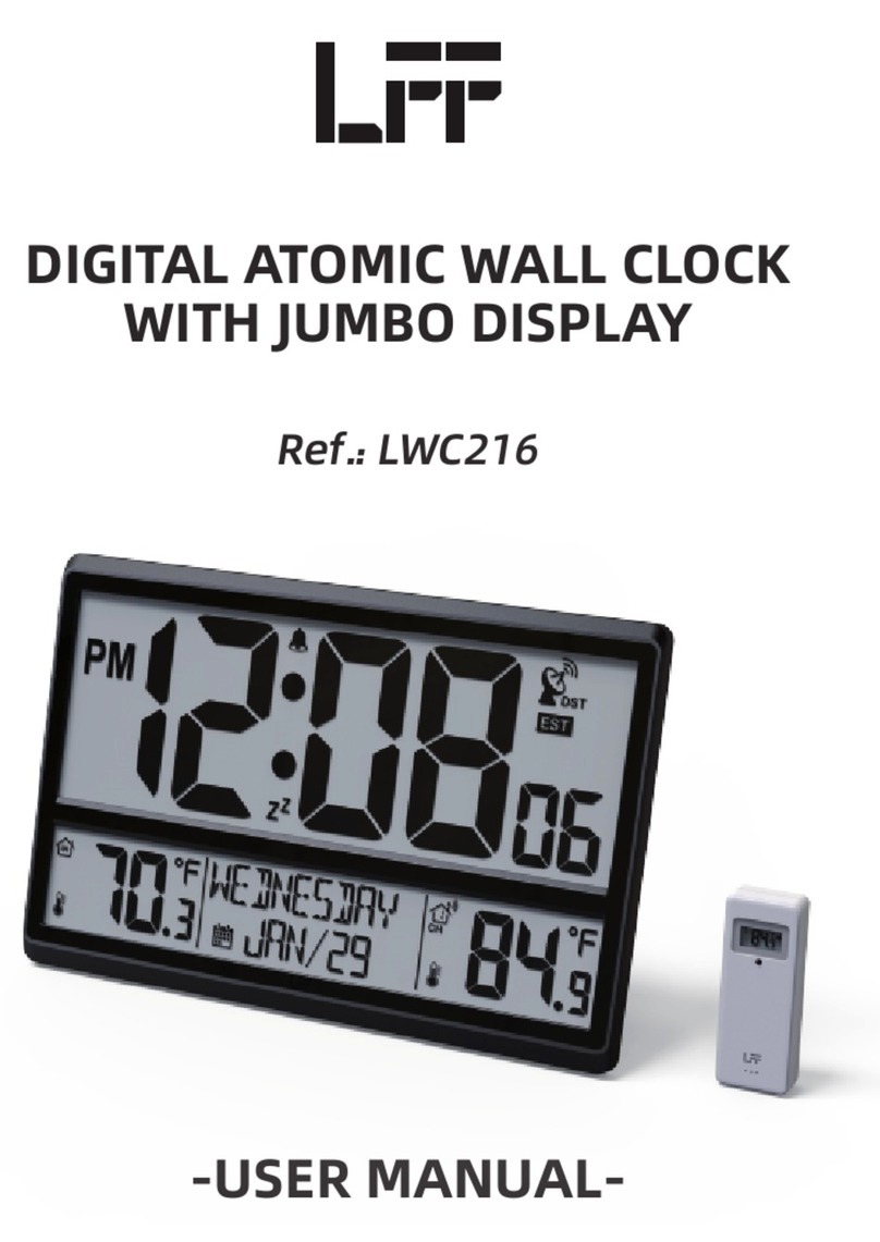
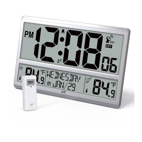
LFF LWC100 User manual

-USER MANUAL-
DIGITAL ATOMIC WALL CLOCK
WITH JUMBO DISPLAY
Ref.: LWC100

-USER MANUAL-
DIGITAL ATOMIC WALL CLOCK
WITH JUMBO DISPLAY
Ref.: LWC100
PACKAGE LIST
ITEM NO PART NAME FIGURE QTY
1
2
3
DIGITAL ATOMIC
WALL CLOCK
OUTDOOR SENSOR
USER MANUAL
1
1
1
1

2
1
6
11
7 108 9
2 3 4 5
1 WALL CLOCK UNIT

3
1-
2-
3-
4-
5-
6-
7-
8-
9-
10-
11-
12-
13-
14-
15-
16-
17-
Time display
Alarm indicator
Atomic clock indicator
DST (Daylight Savings Time) indicator
Time Zone (EST, CST, MST, PST, AKT, HST, AST, NST)
Indoor tempertaure/humidity reading
Calendar with month, date, year and day display
Channel indicator
Outdoor sensor signal strength indicator
Outdoor tempertaure/humidity reading
Battery door (4 x AA batteries)
SET button
Alarm button
▲ button
▼/RCC (Radio Controlled Clock) button
Channel button
Reset button
• Jumbo LCD display.
• 5 functional buttons: SET, ALARM, ▲, ▼/RCC, CHANNEL.
• Self setting accurate atomic time function.
• Time display: Hour, minute, second.
• Calendar display: Month, date, year and weekday written in full letters in English.
• 8 time zones: EST, CST, MST, PST, AKT, HST, AST, NST.
• Alarm with snooze function.
• Displays Indoor & outdoor temperature/humidity.
• Low battery indication for both wall clock and wireless sensor.
• Supports up to 3 optional wireless sensors.
2 MAIN FEATURES
12 13 14 15 1716

• Temperature/humidity measurement.
• Low battery indication.
1
2
3
4
5
LED: Flashes when the unit t ransmits a reading
Wall mount
Channel switch: Channel 1, 2, 3 inside battery compartment
Battery compartment: Use 2 x AAA batteries
Battery door
1
2
3
45
4
MAIN FEATURES
3 OUTDOOR TEMPERATURE/HUMIDITY SENSOR

First of all, it needs to do the pairing between outdoor remote sensor and wall
clock. Please follow below procedures to pair the sensor.
1. Insert 4 new “AA” batteries into the wall clock.
The screen is turned on. It starts to search sensor and register the received
sensor. During pairing, the signal strength indicator will animate until the
sensor signal is received or for 3 minutes if no signal available.
Please select the correct time zone before RCC search.
2. Slide the switch to CH1 of the outdoor sensor and Insert 2 new “AAA”batteries.
The wireless remote sensor will transmit the signal and LED will flash during
transmission.
Note : If no sensor(s) is paired, you can pair the sensor(s) again manually by
pressing and holding the CHANNEL key for 3s. Please refer to “10 SEARCH FOR
OUTDOOR SENSOR”.
5
PAIR THE OUTDOOR REMOTE SENSOR
4 FIRST TIME TO USE

6. When the wall clock detects the atomic clock signal, the signal strength indicator
will be animated.
5. After 3 min sensor pairing time, the wall clock will automatically receive atomic
clock signal, the tower icon will be flashing.
3. Keep the outdoor sensor 5-10 feet from the wall clock.
4. When the RF connection is established, the temperature readings will appear on
the station.
6
7. Put the wall clock away from interference, such as electronic devices
(TV, computer, microwave, radio, etc.)
8. When the wall clock signal is received successfully , the time and date
will be updated. The Atomic Time tower icon will be solid.

9. Allow the outdoor sensor and wall clock to sit together for 15 minutes to
establish a strong connection.
10. Do not press button for 15 minutes.
11. After 15 minutes, place the sensor in a shaded outdoor location.
7
• The wall clock automatically begins search WWVB signal and update
the time every day at 1:00am,2:00am,3:00am,4:00am,5:00am.
• The Atomic Time tower icon will flash while searching and will be solid
when it has connected.
Manual RCC Reception
You can receive the atomic clock signal manually. In Normal display, press and
hold the ▼/RCC over 3 sec to receive the atomic clock signal manually.
The tower icon is flashing and will start atomic clock reception.
When the atomic clock signal is received successfully, the time and date
will be updated.
During atomic clock reception, press and release "▼/RCC" key over 3s to
exit atomic clock reception.
For information about WWVB, visit
www.nist.gov/pml/div688/grp40/wwvb.cfm
5 ATOMIC CLOCK RECEPTION

8
SETTING ORDER
In Normal display, press and hold SET over 3s to enter setting mode.
Press and release ▲ and ▼ to adjust the values. Hold to adjust quickly.
Press and release SET to confirm and move to the next item.
1. RCC ON/OFF
4. Year
7. 12H/24H
3. DST ON/OFF
6. Day
9. Minute
2. Time Zone
5. Month
8. Hour
2.) When Zone EST icon flashes, press ▲ or ▼ button to set a different time zone
(EST=Eastern, CST=Central, MST=Mountain, PST=Pacific, AKT=Alaska, HST=Hawaii,
AST=Atlantic, NST=Newfoundland). Press SET to select DST on/off.
3.) When DST ON flashes, press ▲ or ▼ button to select DST on/off. Press SET to
select Year.
4.) When Year flashes, press ▲ or ▼ to adjust the year. Press SET to select Month.
5.) When Month flashes, press ▲ or ▼ to adjust the month. Press SET to select date.
6.) When Date flashes, press ▲ or ▼ to adjust the date. Press SET to select 12/24
hour time format.
7.) When 12 Hr flashes, press ▲ or ▼ to adjust 12 hour or 24 hour time format.
Press SET to select hours.
8.) When Hour flashes, press ▲ or ▼ to adjust the hours. Press SET to select minute.
9.) When Minute flashes, press ▲ or ▼ to adjust the minutes. Press SET to save all
settings and exit the setting.
1.) Press and hold the SET button entering the settings. RCC ON flashes. Press
▲ and ▼ to set RCC on/off. Press SET to select Time Zone.
Note:
If RCC OFF is selected, you will skip Time Zone and DST settings and move
year setting.
6 SETTING MENU

9

10
1. Press and hold ALARM button over 3s entering alarm setting. Alarm Hour flashes,
press ▲ or ▼ to adjust the alarm hours. Press ALARM button to select the
alarm minute.
2. Alarm Minute flashes, press ▲ or ▼ to adjust the alarm minutes.
Press ALARM button to exit alarm setting.
The indicator will be shown on the display indicating the alarm is now ON.
Note :
• To view the set alarm time, press the ALARM button, the alarm time will show
for 2 seconds.
• The alarm will sound for 2 minutes a the programmed time.
DEACTIVATE/ACTIVATE ALARM
Press the ALARM button and use ▲ button to select the Alarm ON or OFF.
The indicator will show on the display when the alarm is ON and not show on
the display when the alarm is OFF.
When the alarm rings, press SET button to pause the alarm for 5 minutes.
The snooze indicator ZZ icon keeps flashing.
When the alarm rings, press any button except SET button to stop the alarm
for 24 hours.
7 SET ALARM TIME
8 SNOOZE FUNCTION

11
• When battery indicator next to the outdoor temperature, replace batteries
in your outdoor sensor.
• When battery indicator shows next to your atomic tower icon, replace
batteries in your wall clock.
• In Normal display, press and hold CHANNEL over 3s to search the outdoor
temperature/humidity sensor.
• The wall clock can support up to 3 sensors with different channels 1/2/3.
• The signal strength icon will animate until the sensor(s) signal is received, or
for 5 minutes if no signal available.
In Normal display, press and release ▼ to interchange the temperature unit
between degree Celsius and degree Fahrenheit.
• In Normal display, press and release CHANNEL to interchange the reading
display for the outdoor temperature/humidity sensors.
• There are CH1, CH2 CH3 or cycle display.
• In cycle display mode , the outdoor temperature reading will be switched
every 3s.
If there is malfunction of the clock, press RESET to restart the clock.
9 LOW BATTERY INDICATION
10 SEARCH FOR OUTDOOR SENSOR
12 SWITCH READING DISPLAY FOR THE OUTDOOR
TEMPERATURE/HUMIDITY SENSORS
11 SWITCH TEMPERATURE UNIT
13 RESET

12
• Mounting under an eave or deck rail works well.
• Mount the remote sensor on the North side where to prevent sun from
causing incorrect readings.
• Be sure the outdoor sensor is mounted vertically to drain moisture.
• Mount at least 6 feet in the air for a strong RF (radio frequency) signal.
• To prevent wireless interference, place units at least 3 ft (0.9 m) away from
electronic devices (TV, computer, microwave, radio, etc.)
• To maximize atomic signal reception, place the sensor away from large
metallic items, thick walls, metal surfaces, or other objects that may limit
radio communication.
• The maximum wireless transmission range must be within 330 feet (100m)
in open air, not including walls and floors.
16 IMPORTANT PLACEMENT GUIDELINES
Indoor
Outdoor
• Temperature Range: 14.1°F to 122.0°F (-9.9°C to 50.0°C)
• Humidity Range: 1% to 99%
• Temperature Range: -58.0°F to 158.0°F (-50.0°C to 70.0°C)
Note: Temperature below -4°F require Lithium batteries in
the outdoor sensor
• Humidity Range: 1% to 99%
• Distance: 330ft (100m)
• Transmission frequency: 433MHz
Power
Dimension
• Wall clock: 4 x AA 1.5V, alkaline batteries
• Sensor: 2 x AAA 1.5V, alkaline batteries
• Wall clock: 14.25 x 9.29 x 1.12 inches
• Sensor: 1.57 x 4.09 x 1.02 inches
15 SPECIFICATIONS
• The both the wall clock and outdoor transmitter have a table top and wall
mounting structure.
• For the clock, use the recessed hole/holes on at the back of the clock to hang
it or pull out the back-stand for table top use.
• For the transmitter, use the hang hole or place the unit in an area protected
from direct rain.
14 USE THE WALL MOUNT

13
This device complies with part 15 of the FCC Rules. Operation is subject to the
following two conditions:
1. This device may NOT cause harmful interference.
2. This device must accept any interference received, including interference
that may cause undesired operation.
NOTE:
This equipment has been tested and found to comply with the limits for a Class B
digital device, pursuant to Part 15 of the FCC Rules. These limits are designed to
provide reasonable protection against harmful interference in a residential
installation. This equipment generates — and can radiate — radio frequency energy
and, if not installed and used in accordance with the instructions, may cause
harmful interference to radio communications.
However, there is no guarantee that interference will not occur in a particular
installation. If the equipment does not cause harmful interference to radio or
television reception, which can be determined by turning the equipment off and on,
the user is encouraged to try to correct the interference by one or more of the
following measures:
• Reorient or relocate the receiving antenna.
• Increase the separation between the equipment and the receiver.
• Connect the equipment into an outlet on a circuit different from that to
which the receiver is connected.
• Consult the dealer or an experienced radio/TV technician for help.
WARNING:
Changes or modifications to this unit not expressly approved by the party
responsible for compliance could void the user’s authority to operate the
equipment.
17 FCC STATEMENT

DIGITAL ATOMIC WALL CLOCK
Made in China
LWC100
support@lfftech.com
Table of contents
Other LFF Clock manuals
Popular Clock manuals by other brands
La Crosse Technology
La Crosse Technology WS-8418AL-IT instruction manual

Perel
Perel WC113 user manual

BOE
BOE VFD48-1202FN Assembly instructions

L’EPEE 1839
L’EPEE 1839 LE DUEL PERPETUEL TOURBILLON User instructions

Sapling
Sapling Saw 4 installation manual

La Crosse Technology
La Crosse Technology WT-3161WH manual