Service Manual 163
■Error Indicator
•The function is to self-diagnoisis airconditioner and express the troubles identifically if there is any trouble.
•Error mark is ON/OFF for the operation LED of evaporator body in the same manner as the following table.
•If more than two troubles occur simultaneously, primarily the highest trouble fo error code is expressed.
•After error occurrence, if error is released, error LED is also released simultaneously.
•To operate again on the occurrence of error code, be sure to turn off the power and then turn on.
•Having or not of error code is different from Model.
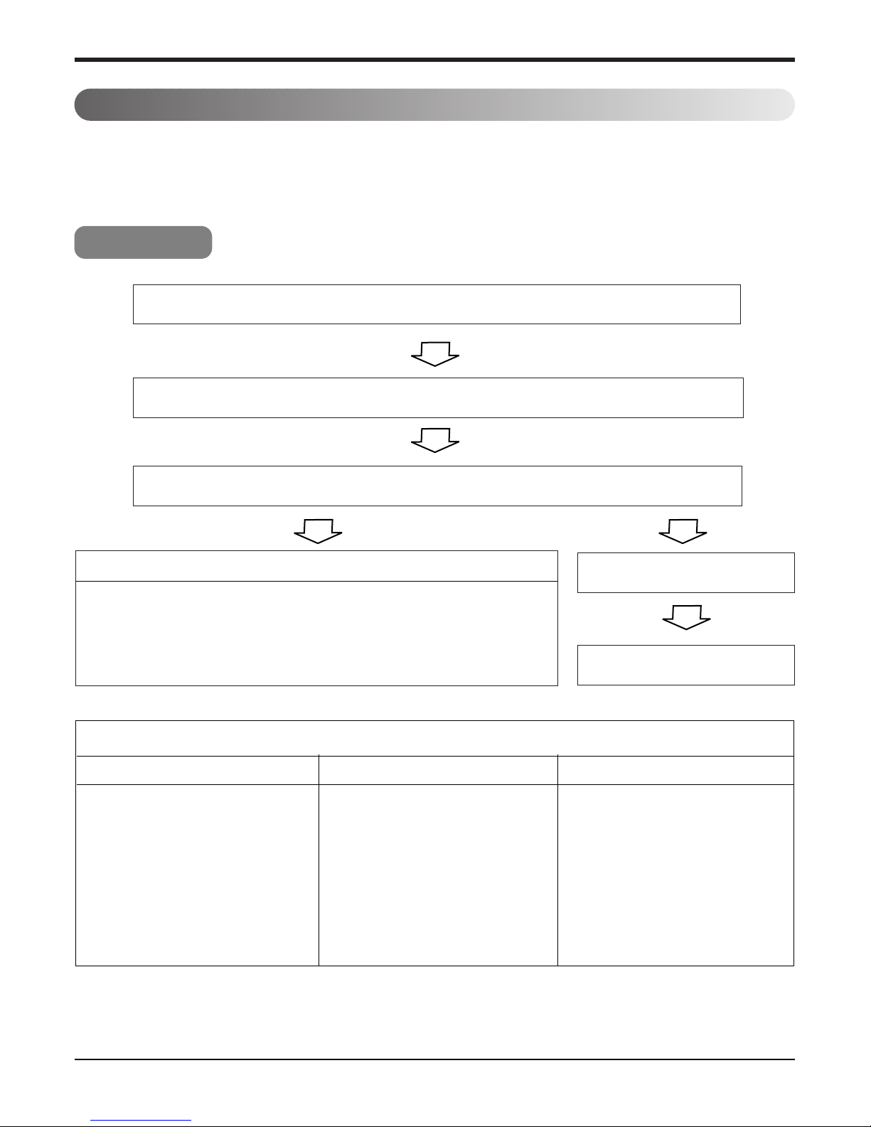
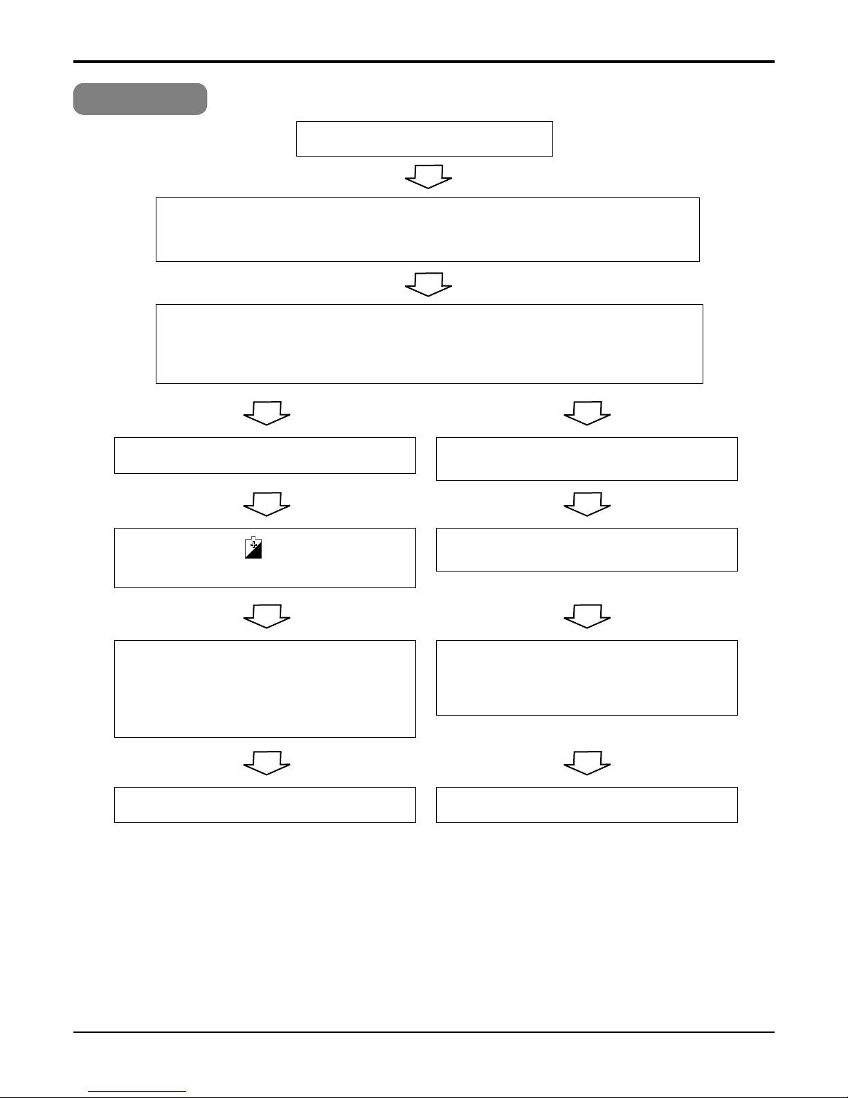
Troubleshooting Guide
Self-diagnosis Function
Indoor Error
Error code Description INV TPS LED 1
(Red) LED 2
(Green) Indoor
Status
00 No Error ON
01 Indoor Room themistor error 1time OFF
02 Indoor in-piping sensor error 2times OFF
03 Remote controller error 3times OFF
04 Drain Pump error 4times OFF
05 Communcation error between in and out 5times OFF
06 Indoor Out-Piping sensor error 6times OFF
07 Differnt mode operation 7times OFF
Outdoor Error
Error Code Description INV TPS LED 1
(Red) LED 2
(Green) Indoor
Status
21 DC Peak (IPM Fault) 2times 1time OFF
22 CT 2(Max CT) 2times 2times OFF
23 DC Link Low Volt. 2times 3times OFF
24 L_P/Heater Sink 2times 4times OFF
25 Low voltage / Over voltage 2times 5times OFF
26 DC Comp Position Error 2times 6times OFF
27 PSC Fault Error 2times 7times OFF
28 DC Link High Volt 2times 8times OFF
32 D-Pipe High (INV) 3times 2times OFF
33 D-Pipe High (Normal) 3times 3times OFF
40 CT Sensor (Open/Short) 4times OOFF
41 INV. D-PipeTh Error(Open/Short) 4times 1time OFF
44 Outdoor air Th Error(Open/Short) 4times 4times OFF
45 Cond. Pipe Th Error(Open/Short) 4times 5times OFF
46 Suction Pipe Error(Open/Short) 4times 6times OFF
47 Const D-pipe Th Error(Open/Short) 4times 7times OFF
51 Capacity over 5times 1time OFF
53 Signal error (Indoor ↔Outdoor) 5times 3times OFF
60 EEPROM Check Sum Error 6times OOFF
61 Cond. Pipe High 6times 1time OFF
62 Heatsink High 6times 2times OFF
63 Cond. Pipe Low 6times 3times OFF
65 Heatsoml Th error (Open/Short) 6times 5times OFF


 null")