LG ABNW18GM1AO User manual

Ceiling concealed duct - Middle static pressure
MULTI/SINGLE
Indoor unit
1.List of Functions
2.Specifications
3.Dimensions
4.Piping diagrams
5.Wiring diagrams
6.External static pressure & Air flow
7.Sound levels
8.Installation

2
MULTI/SINGLE Indoor unit Ceiling concealed duct - Middle static pressure
1. List of functions
List of function
Category Functions
ABNW18GM1A0 [CM18 N14], ABNW24GM1A0 [CM24 N14]
ABNW30GM1A0 [UM30 N14], ABNW36GM2A0 [UM36 N24]
ABNW42GM2A0 [UM42 N24], ABNW48GM3A0 [UM48 N34]
ABNW60GM3A0 [UM60 N34]
Air flow
Air supply outlet 1
Airflow direction control (left & right) X
Airflow direction control (up & down) X
Auto swing (left & right) X
Auto swing (up & down) X
Airflow steps (fan/cool/heat) 3 / 3 / 3
Chaos wind(auto wind) X
Jet cool/heat X / X
Swirl wind X
Air purifying
Triple filter (Deodorizing) X
Air purifier (Plasma) X
Air purifier (Ionizer) X
Allergy Safe filter X
Long-life prefilter (washable / anti-fungus) O
Installation
Drain pump ABDPG
E.S.P. control* O
Electric heater X
High ceiling operation* X
Reliability Hot start O
Self diagnosis O
Convenience
Auto changeover O (Single Only)
Auto cleaning X
Auto operation(artificial intelligence) O (Multi Only)
Auto Restart O
Child lock* O
Forced operation X
Group control* O
Sleep mode O
Timer(on/off) O
Timer(weekly)* O
Two thermistor control* O
Auto Elevation Grille X
Special Functions Wi-Fi X
Humidity Control X
Wireless Remote Controller O (Accessory)
Wired Remote Controller O**
Network Solution(LGAP) O
Note
1. O : Applied, X : Not applied, Embeded : Included with product.
Accessory : Ordered and purchased separately the accessory package referring to the model name provided and install at field.
Accessory line-ups varies by region, so check your local catalogue or local sales material.
2. Some functions can be limited by remote controller.
3. In case of ducted type indoor units using the wireless remote controller, it needs to connect the wired remote controller for received the signal of that.
4. In case of cassette type indoor units, Plasma kit and Auto Elevation Grille functions are not applicable at the same time.
5. * : These functions need to connect the wired remote controller.
6. ** : It is included by default when the product is manufactured.

MULTI/SINGLE Indoor unit
1. List of functions
3
Ceiling concealed duct - Middle static pressure
Accessory Compatibility List
Category Product Remark
ABNW18GM1A0 [CM18 N14],
ABNW24GM1A0 [CM24 N14]
ABNW30GM1A0 [UM30 N14],
ABNW36GM2A0 [UM36 N24]
ABNW42GM2A0 [UM42 N24],
ABNW48GM3A0 [UM48 N34]
ABNW60GM3A0 [UM60 N34]
Wireless Remote Controller PQWRHQ0FDB Heat Pump O***
Wired
Remote
Controller
Simple PQRCVCL0Q(W) Simple O
PQRCHCA0Q(W) for Hotel O
Standard
PREMTB001 Standard II (White) O
PREMTBB01 Standard II (Black) O
PREMTB100** Standard III (White) O
PREMTBB10** Standard III (Black) O
Premium PREMTA000(A/B) Premium O
Dry contact
Simple Contact PDRYCB000 Simple Dry Contact O
Communication type
PDRYCB400 2 Points Dry Contact (For Setback) O
PDRYCB300 For 3rd Party Thermostat O
PDRYCB500 For Modbus O
Gateway IDU PI485 PHNFP14A0 Without case X
PSNFP14A0 With case X
ETC
Remote temperature
sensor PQRSTA0 - O
Zone controller ABZCA - O
COဌSensor PES-C0RV0 For ERV, ERV DX Indoor units X
Group control wire PZCWRCG3 0.25m O
2-Remo Control Wire PZCWRC2 0.25m O
Extension Wire PZCWRC1 10m O
Wi-Fi Controller* PWFMDD200 - X
Human detecting sensor PTVSMA0 - X
Note
1. O: Possible, X: Impossible, - : Not applicable, Embeded : Included with product.
2. * : Some advanced functions controlled by individual controller cannot be operated.
3. ** : It could not be operated some functions.
4. If you need more detail, please refer to the BECON PDB or the manual of product.
(http://partner.lge.com/global : Home > Doc.Library > Product > Control(BECON))
• *** : In case of ducted type indoor units using the wireless remote controller, it needs to connect the wired remote controller for received the
signal of that.

4
MULTI/SINGLE Indoor unit Ceiling concealed duct - Middle static pressure
2. Specifications
Model Name ABNW18GM1A0
[CM18 N14]
ABNW24GM1A0
[CM24 N14]
Power Supply V, Ø, Hz 220-240, 1, 50 220-240, 1, 50
220, 1, 60 220, 1, 60
Power Input W 80 90
Running Current A 0.40 0.50
Dimensions Body W x H x D mm 900 × 270 × 700 900 × 270 × 700
W x H x D inch 35-7/16 x 10-5/8 x 27-9/16 35-7/16 x 10-5/8 x 27-9/16
Net Weight Body kg (lbs) 23.8 (52.5) 24.2 (53.4)
Heat Exchanger (Row x Column x Fins per inch) x No. - (2 x 13 x 18) x 1 (2 x 13 x 18) x 1
Face Area m2 (ft2)0.21 (2.25) 0.21 (2.25)
Fan
Type - Sirocco Fan Sirocco Fan
Air Flow
Rate
High-static
Mode
(Factory
Set)
H / M / L m3/min 16.5 / 14.5 / 13.0 18.0 / 16.5 / 14.5
H / M / L ft3/min 582 / 512 / 459 635 / 582 / 512
External Static
Pressure Pa (mmAq) 58.8 (6) 58.8 (6)
Fan Motor Type - BLDC BLDC
Output W x No. 136.5 x 1 136.5 x 1
Sound Pressure Level H / M / L dB(A) 34 / 32 / 30 35 / 34 / 32
Sound Power Level Max. dB(A) 59 60
Piping Connections
Liquid mm(inch) Ø 6.35 (1/4) Ø 9.52
(3/8)
Ø 6.35
(1/4)*
Gas mm(inch) Ø 12.7 (1/2) Ø 15.88
(5/8)
Ø 12.7
(1/2)*
Drain (O.D. / I.D.) mm(inch) Ø 32.0(1-1/4) /
25.0(31/32)
Ø 32.0(1-1/4) /
25.0(31/32)
Safety Devices - Fuse Fuse
-- -
Power and Communication Cable (included Earth) No. x mm2 (AWG) 4C x 0.75 (18) 4C x 0.75 (18)
Note
1. Due to our policy of innovation some specifications may be changed without notification.
2. Wiring cable size must comply with the applicable local and national code. And “Electric characteristics” chapter should be considered for electrical
work and design. Especially the power cable and circuit breaker should be selected in accordance with that.
3. Sound Level Values are measured at Anechoic chamber. Therefore, these values depend on the ambient conditions and values are normally higher
in actual operation.
4. Capacities are net capacities and based on the following conditions. Refer to the Outdoor Unit Specifications for calculating the real capacity.
• Cooling : Indoot Ambient Temp. 27°CDB / 19°CWB, Outdoor Ambient Temp. 35°CDB / 24°CWB
• Heating : Indoot Ambient Temp. 20°CDB / 15°CWB, Outdoor Ambient Temp. 7°CDB / 6°CWB
• Interconnected Pipe is standard length and difference of Elevation (Outdoor ~ Indoor Unit) is Zero.
* : For combined with Multi F/FDX system, socket provided with indoor units should be connected.

MULTI/SINGLE Indoor unit
2. Specifications
5
Ceiling concealed duct - Middle static pressure
Model Name ABNW30GM1A0
[UM30 N14]
ABNW36GM2A0
[UM36 N24]
Power Supply V, Ø, Hz 220-240, 1, 50 220-240, 1, 50
220, 1, 60 220, 1, 60
Power Input W 150 210
Running Current A 0.80 1.30
Dimensions Body W x H x D mm 900 × 270 × 700 1,250 × 270 × 700
W x H x D inch 35-7/16 x 10-5/8 x 27-9/16 49-7/32 x 10-5/8 x 27-9/16
Net Weight Body kg (lbs) 25.3 (55.8) 36.0 (79.4)
Heat Exchanger (Row x Column x Fins per inch) x No. - (3 x 13 x 18) x 1 (2 x 13 x 18) x 1
Face Area m2 (ft2)0.21 (2.25) 0.30 (3.27)
Fan
Type - Sirocco Fan Sirocco Fan
Air Flow
Rate
High-static
Mode
(Factory
Set)
H / M / L m3/min 22.0 / 20.0 / 18.0 32.0 / 28.0 / 24.0
H / M / L ft3/min 777 / 706 / 635 1,130 / 988 / 847
External Static
Pressure Pa (mmAq) 58.8 (6) 58.8 (6)
Fan Motor Type - BLDC BLDC
Output W x No. 136.5 x 1 295 x 1
Sound Pressure Level H / M / L dB(A) 37 / 35 / 34 36 / 34 / 33
Sound Power Level Max. dB(A) 62 60
Piping Connections
Liquid mm(inch) Ø 9.52 (3/8) Ø 9.52 (3/8)
Gas mm(inch) Ø 15.88 (5/8) Ø 15.88 (5/8)
Drain (O.D. / I.D.) mm(inch) Ø 32.0(1-1/4) /
25.0(31/32)
Ø 32.0(1-1/4) /
25.0(31/32)
Safety Devices - Fuse Fuse
-- -
Power and Communication Cable (included Earth) No. x mm2 (AWG) 4C x 0.75 (18) 4C x 0.75 (18)
Note
1. Due to our policy of innovation some specifications may be changed without notification.
2. Wiring cable size must comply with the applicable local and national code. And “Electric characteristics” chapter should be considered for electrical
work and design. Especially the power cable and circuit breaker should be selected in accordance with that.
3. Sound Level Values are measured at Anechoic chamber. Therefore, these values depend on the ambient conditions and values are normally higher
in actual operation.
4. Capacities are net capacities and based on the following conditions. Refer to the Outdoor Unit Specifications for calculating the real capacity.
• Cooling : Indoot Ambient Temp. 27°CDB / 19°CWB, Outdoor Ambient Temp. 35°CDB / 24°CWB
• Heating : Indoot Ambient Temp. 20°CDB / 15°CWB, Outdoor Ambient Temp. 7°CDB / 6°CWB
• Interconnected Pipe is standard length and difference of Elevation (Outdoor ~ Indoor Unit) is Zero.

2. Specifications
6
MULTI/SINGLE Indoor unit Ceiling concealed duct - Middle static pressure
Model Name ABNW42GM2A0
[UM42 N24]
ABNW48GM3A0
[UM48 N34]
Power Supply V, Ø, Hz 220-240, 1, 50 220-240, 1, 50
220, 1, 60 220, 1, 60
Power Input W 260 180
Running Current A 1.50 1.10
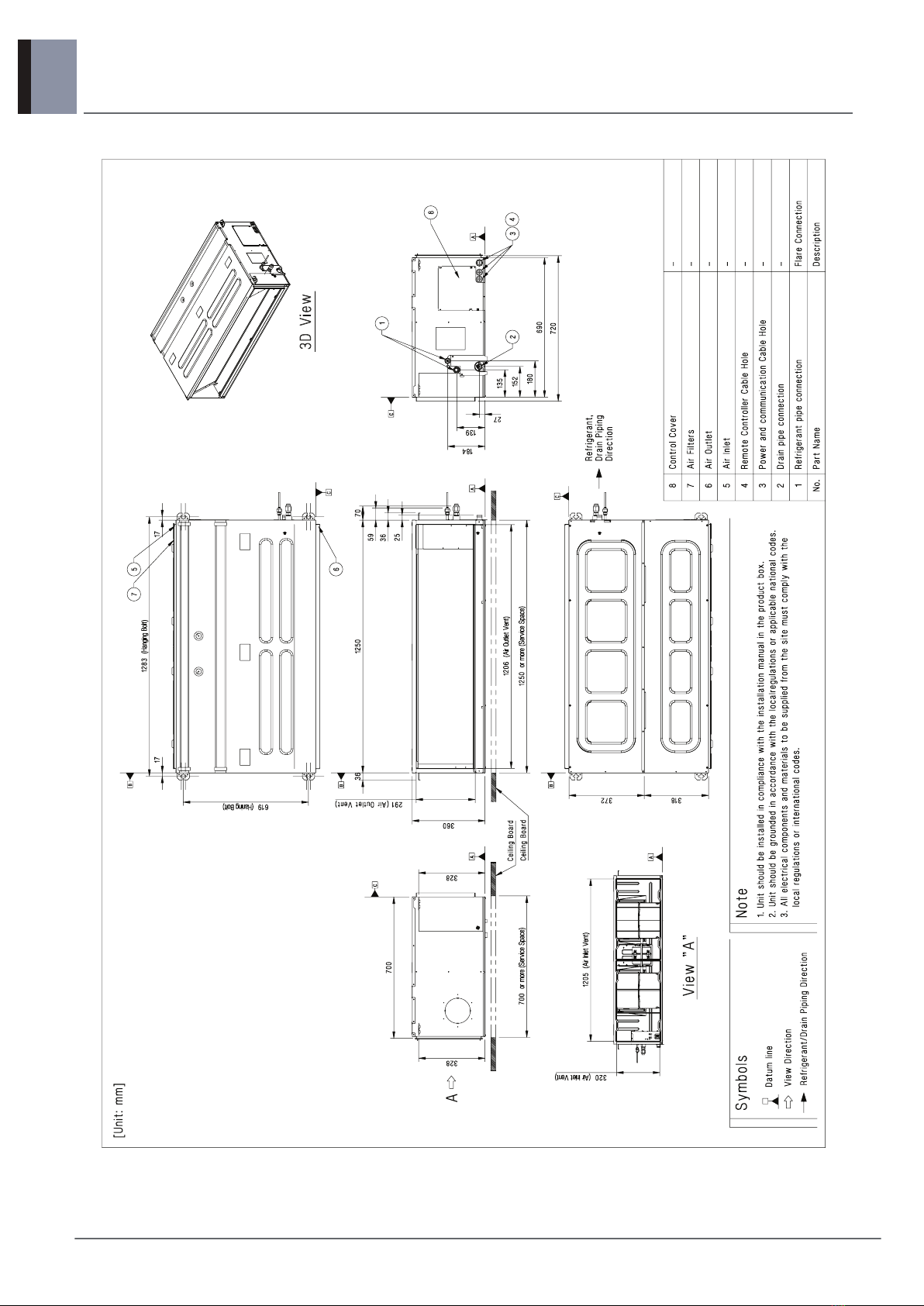
Dimensions Body
W x H x D mm 1,250 × 270 × 700 1,250 × 360 × 700
W x H x D inch 49-7/32 x 10-5/8 x 27-9/16 49-7/32 x 14-3/16 x
27-9/16
Net Weight Body kg (lbs) 37.0 (81.6) 41.0 (90.3)
Heat Exchanger (Row x Column x Fins per inch) x No. - (3 x 13 x 18) x 1 (3 x 16 x 18) x 1
Face Area m2 (ft2)0.30 (3.27) 0.36 (3.85)
Fan
Type - Sirocco Fan Sirocco Fan
Air Flow
Rate
High-static
Mode
(Factory
Set)
H / M / L m3/min 38.0 / 33.0 / 28.0 40.0 / 34.0 / 28.0
H / M / L ft3/min 1,341 / 1,165 / 988 1,412 / 1,200 / 988
External Static
Pressure Pa (mmAq) 58.8 (6) 58.8 (6)
Fan Motor Type - BLDC BLDC
Output W x No. 295 x 1 290 x 1
Sound Pressure Level H / M / L dB(A) 38 / 36 / 34 39 / 37 / 35
Sound Power Level Max. dB(A) 62 65
Piping Connections
Liquid mm(inch) Ø 9.52 (3/8) Ø 9.52 (3/8)
Gas mm(inch) Ø 15.88 (5/8) Ø 15.88 (5/8)
Drain (O.D. / I.D.) mm(inch) Ø 32.0(1-1/4) /
25.0(31/32)
Ø 32.0(1-1/4) /
25.0(31/32)
Safety Devices - Fuse Fuse
-- -
Power and Communication Cable (included Earth) No. x mm2 (AWG) 4C x 0.75 (18) 4C x 0.75 (18)
Note
1. Due to our policy of innovation some specifications may be changed without notification.
2. Wiring cable size must comply with the applicable local and national code. And “Electric characteristics” chapter should be considered for electrical
work and design. Especially the power cable and circuit breaker should be selected in accordance with that.
3. Sound Level Values are measured at Anechoic chamber. Therefore, these values depend on the ambient conditions and values are normally higher
in actual operation.
4. Capacities are net capacities and based on the following conditions. Refer to the Outdoor Unit Specifications for calculating the real capacity.
• Cooling : Indoot Ambient Temp. 27°CDB / 19°CWB, Outdoor Ambient Temp. 35°CDB / 24°CWB
• Heating : Indoot Ambient Temp. 20°CDB / 15°CWB, Outdoor Ambient Temp. 7°CDB / 6°CWB
• Interconnected Pipe is standard length and difference of Elevation (Outdoor ~ Indoor Unit) is Zero.

MULTI/SINGLE Indoor unit
2. Specifications
7
Ceiling concealed duct - Middle static pressure
Model Name ABNW60GM3A0
[UM60 N34]
Power Supply V, Ø, Hz 220-240, 1, 50
220, 1, 60
Power Input W 290
Running Current A 1.65
Dimensions Body W x H x D mm 1,250 × 360 × 700
W x H x D inch 49-7/32 x 14-3/16 x 27-9/16
Net Weight Body kg (lbs) 41.0 (90.3)
Heat Exchanger (Row x Column x Fins per inch) x No. - (3 x 16 x 18) x 1
Face Area m2 (ft2)0.36 (3.85)
Fan
Type - Sirocco Fan
Air Flow
Rate
High-static
Mode
(Factory
Set)
H / M / L m3/min 50.0 / 45.0 / 40.0
H / M / L ft3/min 1,765 / 1,589 / 1,412
External Static
Pressure Pa (mmAq) 58.8 (6)
Fan Motor Type - BLDC
Output W x No. 290 x 1
Sound Pressure Level H / M / L dB(A) 42 / 40 / 39
Sound Power Level Max. dB(A) 66
Piping Connections
Liquid mm(inch) Ø 9.52 (3/8)
Gas mm(inch) Ø 15.88 (5/8)
Drain (O.D. / I.D.) mm(inch) Ø 32.0(1-1/4) / 25.0(31/32)
Safety Devices - Fuse
--
Power and Communication Cable (included Earth) No. x mm2 (AWG) 4C x 0.75 (18)
Note
1. Due to our policy of innovation some specifications may be changed without notification.
2. Wiring cable size must comply with the applicable local and national code. And “Electric characteristics” chapter should be considered for electrical
work and design. Especially the power cable and circuit breaker should be selected in accordance with that.
3. Sound Level Values are measured at Anechoic chamber. Therefore, these values depend on the ambient conditions and values are normally higher
in actual operation.
4. Capacities are net capacities and based on the following conditions. Refer to the Outdoor Unit Specifications for calculating the real capacity.
• Cooling : Indoot Ambient Temp. 27°CDB / 19°CWB, Outdoor Ambient Temp. 35°CDB / 24°CWB
• Heating : Indoot Ambient Temp. 20°CDB / 15°CWB, Outdoor Ambient Temp. 7°CDB / 6°CWB
• Interconnected Pipe is standard length and difference of Elevation (Outdoor ~ Indoor Unit) is Zero.

8
MULTI/SINGLE Indoor unit Ceiling concealed duct - Middle static pressure
3. Dimensions
ABNW18GM1A0 [CM18 N14] / ABNW24GM1A0 [CM24 N14] / ABNW30GM1A0 [UM30 N14]
Supplied with product
Chassis Code : M1

MULTI/SINGLE Indoor unit
3. Dimensions
9
Ceiling concealed duct - Middle static pressure
ABNW36GM2A0 [UM36 N24] / ABNW42GM2A0 [UM42 N24]
Chassis Code : M2

3. Dimensions
10
MULTI/SINGLE Indoor unit Ceiling concealed duct - Middle static pressure
ABNW48GM3A0 [UM48 N34] / ABNW60GM3A0 [UM60 N34]
Chassis Code : M3
DWG No. : TBB35394101_rev01

11
MULTI/SINGLE Indoor unit Ceiling concealed duct - Middle static pressure
4. Piping diagrams
Model : ABNW-GM1A0 [CM- N14]
Refrigerant pipe connection port diameters
[Unit : mm]
* : For combined with Multi F/FDX system, socket provided with indoor units should be connected.
Description PCB Connector
Thermistor for suction air temperature CN-ROOM
Thermistor for evaporator inlet temperature CN-PIPE / IN
Thermistor for evaporator outlet temperature CN-PIPE / OUT
Model Gas Liquid
ABNW18GM1A0 [CM18 N14] Ø12.7 Ø6.35
ABNW24GM1A0 [CM24 N14] Ø15.88 Ø9.52
* Ø12.7 * Ø6.35
ABNW30GM1A0 [CM30 N14] Ø15.88 Ø9.52
Sirocco Fan
Heat exchanger Gas pipe connection port
(flare connection)
Liquid pipe connection port
(flare connection)
Cooling
Heating
M
Thermistor for
suction air
temperature
Thermistor for
evaporator outlet
temperature
Thermistor for
evaporator inlet
temperature

4. Piping diagrams
12
MULTI/SINGLE Indoor unit Ceiling concealed duct - Middle static pressure
Models : ABNW-GM2A0 [CM- N24], ABNW-GM3A0 [CM- N34]
Refrigerant pipe connection port diameters
[Unit : mm]
Description PCB Connector
Thermistor for suction air temperature CN-ROOM
Thermistor for evaporator inlet temperature CN-PIPE / IN
Thermistor for evaporator outlet temperature CN-PIPE / OUT
Model Gas Liquid
ABNW36GM2A0 [CM36 N24]
ABNW42GM2A0 [CM42 N24]
ABNW48GM3A0 [CM48 N34]
ABNW60GM3A0 [CM60 N34]
Ø15.88 Ø9.52
Sirocco Fan
Heat exchanger Gas pipe connection port
(flare connection)
Liquid pipe connection port
(flare connection)
Cooling
Heating
M
Thermistor for
suction air
temperature
Thermistor for
evaporator outlet
temperature
Thermistor for
evaporator inlet
temperature

13
MULTI/SINGLE Indoor unit Ceiling concealed duct - Middle static pressure
5. Wiring Diagrams
Model : ABNW18GM1A0 [CM18 N14]

5. Wiring Diagrams
14
MULTI/SINGLE Indoor unit Ceiling concealed duct - Middle static pressure
Model : ABNW24GM1A0 [CM24 N14], ABNW30GM1A0 [CM30 N14]

MULTI/SINGLE Indoor unit
5. Wiring Diagrams
15
Ceiling concealed duct - Middle static pressure
Model : ABNW36GM2A0 [CM36 N24], ABNW42GM2A0 [CM42 N24]

5. Wiring Diagrams
16
MULTI/SINGLE Indoor unit Ceiling concealed duct - Middle static pressure
Model : ABNW48GM3A0 [CM48 N34], ABNW60GM3A0 [CM60 N34]

17
MULTI/SINGLE Indoor unit Ceiling concealed duct - Middle static pressure
6. External Static Pressure & Air Flow
How to Set E.S.P. on the remote controller?
This is the function that decides the strength of the wind for each wind level and because this function is to make
the installation easier.
• If you set ESP incorrectly, the air conditioner may malfunction.
• This setting must be carried out by a certificated-technician.
• When setting ESP value on the product without very weak wind or power wind function, it may not work.
• Please be careful not to change the ESP value for each fan step.
• It does not work to setup ESP value for very low/power step for some products.
• ESP value is available for specific range belongs to the product.
If entering into ESP setup mode by using
button, it indicates as the picture
below.
2
Select ESP fan step by
pressing button.
(01: very low, 02: low, 03:
medium, 04: high, 05:
very high)
3
Move to ESP value setting by pressing
button.
(It is 000 when delivering
from the warehouse.)
4
Press button to setup ESP value.
(It is possible to setup ESP
value from 1 to 255, and 1 is
the smallest and 255 is the
biggest.)
5
If pressing button long for 3
seconds, it enters into remote
controller setter setup mode.
- If pressing once shortly, it enters
into user setup mode. Please press
more than 3 seconds for sure.
1
Function Code ESP value
ESP step
Press button to save.
7
Select ESP fan step again by using
button and setup ESP value, as No. 4
and 5, that corresponds each wind flow
6
Press button to exit.
After setup, it automatically gets out of
setup mode if there is no button input
for 25 seconds.
When exiting without pressing set
button, the manipulated value is not
reflected.
8
Function code,
ESP code
ESP value

6. External Static Pressure & Air Flow
18
MULTI/SINGLE Indoor unit Ceiling concealed duct - Middle static pressure
Installer Setting - Static Pressure Step Setting
This function is applied to only duct type. Setting this in other cases will cause malfunction.
This function is only available on some products.
This is the function that static pressure of the product is divided in 11 steps for setting.
• Static Pressure (Code 06) setting will not be used if Static Pressure Step (Code 32) setting is being used.
• For the static pressure value for each step, refer to the next page Table. 1
When pressing the button and
button simultaneously for more than 3
seconds, the system will be entered into the
installer setting mode.
- After entering into the installer setting
mode, select the static pressure step
setting code value by pressing the
button.
* Static pressure step setting code value : 32
1
Select the desired setting value with the
temperature up(s), down(t) button.
2
When pressing button, currently
established static pressure value will be set
up.
3
When pressing the button and
button simultaneously for more than 3
seconds after the setting has been completed,
the setting mode will be released.
- If there isn’t any button input for more than
25 seconds, the installer setting mode will
also be released.
4
OPER
MODE
OPER
MODE
OPER
MODE
00: use static pressure (code 06) set value
01~ 11: static pressure step (code 32) set value
Function Code Existing condition

MULTI/SINGLE Indoor unit
6. External Static Pressure & Air Flow
19
Ceiling concealed duct - Middle static pressure
Table 1
Model Step CMM
Static Pressure[mmAq(Pa)]
2(20) 2.5(25) 3(29) 4(39) 6(59) 8(78) 10(98) 12(118) 13(127) 14(137) 15(147)
Setting Value
32:01 32:02 32:03 32:04 32:05 32:06 32:07 32:08 32:09 32:10 32:11
ABNW18GM1A0
[CM18 N14]
LOW 13.0 74 76 79 85 93 103 111 117 120 125 128
MID 14.5 79 81 84 89 97 107 114 121 125 128 131
HIGH 16.5 85 87 90 94 103 110 118 125 128 131 134
ABNW24GM1A0
[CM24 N14]
LOW 14.5 79 81 84 89 97 107 114 121 125 128 131
MID 16.5 85 87 90 94 103 110 118 125 128 131 134
HIGH 18.0 90 92 95 99 108 115 122 129 132 135 138
Model Step CMM
Static Pressure[mmAq(Pa)]
2.5(25) 4(39) 5(49) 6(59) 7(69) 8(78) 9(88) 10(98) 11(108) 13(127) 15(147)
Setting Value
32:01 32:02 32:03 32:04 32:05 32:06 32:07 32:08 32:09 32:10 32:11
ABNW30GM1A0
[UM30 N14]
LOW 18.0 96 102 107 104 114 118 122 125 127 132 134
MID 20.0 102 110 114 110 121 125 127 130 133 135 137
HIGH 22.0 110 117 121 118 127 130 133 136 137 138 140
Model Step CMM
Static Pressure[mmAq(Pa)]
4(39) 5(49) 6(59) 7(69) 8(78) 9(88) 10(98) 11(108) 12(118) 13(127) 15(147)
Setting Value
32:01 32:02 32:03 32:04 32:05 32:06 32:07 32:08 32:09 32:10 32:11
ABNW36GM2A0
[UM36 N24]
LOW 24.0 88 91 95 100 101 108 113 115 118 118 118
MID 28.0 93 97 101 105 108 115 118 120 124 124 124
HIGH 32.0 101 105 109 112 115 119 123 126 128 128 128
Model Step CMM
Static Pressure[mmAq(Pa)]
5(49) 6(59) 7(69) 8(78) 9(88) 10(98) 11(108) 12(118) 13(127) 14(137) 15(147)
Setting Value
32:01 32:02 32:03 32:04 32:05 32:06 32:07 32:08 32:09 32:10 32:11
ABNW42GM2A0
[UM42 N24]
LOW 28.0 100 103 106 110 114 118 121 125 128 133 136
MID 33.0 108 111 114 118 122 125 128 131 134 138 141
HIGH 38.0 117 120 124 127 130 133 135 138 141 144 147
Model Step CMM
Static Pressure[mmAq(Pa)]
4(39) 5(49) 6(59) 7(68) 8(78) 9(88) 10(98) 11(108) 12(118) 13(127) 15(147)
Setting Value
32:01 32:02 32:03 32:04 32:05 32:06 32:07 32:08 32:09 32:10 32:11
ABNW48GM3A0
LOW 28 74 76 79 82 89 92 94 96 99 102 107
MID 34 78 82 84 89 94 96 98 101 104 106 112
HIGH 40 83 89 92 94 98 1000 102 105 108 110 116
Model Step CMM
Static Pressure[mmAq(Pa)]
4(39) 5(49) 6(59) 7(68) 8(78) 9(88) 10(98) 11(108) 12(118) 13(127) 15(147)
Setting Value
32:01 32:02 32:03 32:04 32:05 32:06 32:07 32:08 32:09 32:10 32:11
ABNW60GM3A0
LOW 40 82 89 92 94 98 100 102 105 108 110 113
MID 45 90 92 96 98 102 104 106 109 112 114 117
HIGH 50 94 97 1000 104 107 109 112 115 117 119 121

6. External Static Pressure & Air Flow
20
MULTI/SINGLE Indoor unit Ceiling concealed duct - Middle static pressure
Note
1. Be sure to set the value refering table 1. Unexpected set value will cause mal-function.
2. Table 1 is based at 230V. According to the fluctuation of voltage, air flow rate varies.
3. Factory Set(External Static Pressure) each Model
* If it is zero static pressure, please set value below Maximum value.
Model Factory set (E.S.P.) mmAq(Pa)
ABNW18GM1A0
6(59)
ABNW24GM1A0
ABNW30GM1A0
ABNW36GM2A0
ABNW42GM2A0
ABNW48GM3A0
ABNW60GM3A0
Model Maximum value
ABNW18GM1A0 115
ABNW24GM1A0
ABNW30GM1A0
120ABNW36GM2A0
ABNW42GM2A0
ABNW48GM3A0 98
ABNW60GM3A0
This manual suits for next models
16
Table of contents
Other LG Air Conditioner manuals

LG
LG ARNU48GBRZ4 User manual

LG
LG LZ-H015GBA2 User manual

LG
LG Multi V PRHR041 User manual

LG
LG Art Cool LMU240CE User manual

LG
LG LT-D5480HL User manual

LG
LG MFL67870417 User manual

LG
LG LW8013ER Assembly instructions

LG
LG Room air conditioner User manual

LG
LG LM-2561C3L User manual

LG
LG LV-B2461CL User manual
Popular Air Conditioner manuals by other brands

REMKO
REMKO MVX Series Operating and installation instructions

Comet
Comet XRC-3023-WA manual

Kenmore
Kenmore 580.72184 owner's manual

Carrier
Carrier 40VMU012 Series Installation and maintenance instructions

Fujitsu
Fujitsu ABYA36LATN Service manual

TemperZone
TemperZone OPA 2000RKTM01 Installation & maintenance