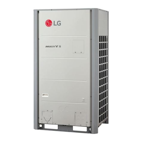
LG APUW100LFT0 User manual

P/NO : MFL68061226
INSTALLATION MANUAL
AIR
CONDITIONER
www.lg.com
Please read this installation manual completely before installing the product.
Installation work must be performed in accordance with the national wiring
standards by authorized personnel only.
Please retain this installation manual for future reference after reading it
thoroughly.
Floor standing
ENGLISH
FRANÇAIS

2TIPS FOR SAVING ENERGY
ENGLISH
• Do not cool excessively indoors. This may be harmful to your health and may consume more elec-
tricity.
• Block sunlight with blinds or curtains while you are operating the air conditioner.
• Keep doors or windows closed tightly while you are operating the air conditioner.
• Adjust the direction of the air flow vertically or horizontally to circulate indoor air.
• Speed up the fan to cool or warm indoor air quickly, in a short period of time.
• Open windows regularly for ventilation as the indoor air quality may deteriorate if the air condi-
tioner is used for many hours.
• Clean the air filter once every 2 weeks. Dust and impurities collected in the air filter may block the
air flow or weaken the cooling / dehumidifying functions.
For your records
Staple your receipt to this page in case you need it to prove the date of purchase or for warranty
purposes. Write the model number and the serial number here:
Model number :
Serial number :
You can find them labeled on the side of each unit.
Dealer’s name :
Date of purchase :
Here are some tips that will help you minimize the power consumption when you use the air
conditioner. You can use your air conditioner more efficiently by referring to the instructions
below:
TIPS FOR SAVING ENERGY

IMPORTANT SAFETY INSTRUCTIONS 3
ENGLISH
IMPORTANT SAFETY INSTRUCTIONS
READ ALL INSTRUCTIONS BEFORE USING THE APPLIANCE.
Always comply with the following precautions to avoid dangerous situations and ensure peak
performance of your product
WARNING
It can result in serious injury or death when the directions are ignored
CAUTION
It can result in minor injury or product damage when the directions are ignored
WARNING
• Installation or repairs made by unqualified persons can result in hazards to you and others.
• Installation work must be performed in accordance with the National Electric Code by quali-
fied and authorized personnel only.
• The information contained in the manual is intended for use by a qualified service technician
familiar with safety procedures and equipped with the proper tools and test instruments.
• Failure to carefully read and follow all instructions in this manual can result in equipment mal-
function, property damage, personal injury and/or death.
Installation
• Always perform grounding. Otherwise, it may cause electric shock.
• Don’t use a damaged power cable. Otherwise, it may cause a fire or electric shock.
• For installation of the product, always contact the service center or a professional installation
agency. Otherwise, it may cause a fire, electric shock, explosion or injury.
• Securely attach the electrical part cover to the indoor unit and the service panel to the outdoor
unit. If the electrical part cover of the indoor unit and the service panel of the outdoor unit are
not attached securely, it could result in a fire or electric shock due to dust, water, etc.
• Always install an earth leakage circuit breaker and a dedicated switching board. No installation
may cause a fire and electric shock.
• Do not keep or use flammable gases or combustibles near the air conditioner. Otherwise, it
may cause a fire or the failure of product.
• Ensure that an installation frame of the outdoor unit is not damaged due to use for a long
time. It may cause injury or an accident.
• Do not disassemble or repair the product randomly. It will cause a fire or electric shock.
• Use a vacuum pump or Inert (nitrogen) gas when doing leakage test or air purge. Do not com-
press air or Oxygen and do not use Flammable gases. Otherwise, it may cause fire or explo-
sion. There is the risk of death, injury, fire or explosion.
• Do not install the product at a place that there is concern of falling down. Otherwise, it may
result in personal injury.
• Use caution when unpacking and installing. Sharp edges may cause injury.
• Do not turn on the breaker or power under condition that front panel, cabinet, top cover, con-
trol box cover are removed or opened. Otherwise, it may cause fire, electric shock, explosion
or death.
• For installation of the product, do not use the pipe less than 5 m. Otherwise, it may cause
damage of compressor and to form dewdrop on the indoor unit. Also, it may cause to de-
crease capacity.
!
!
!

4IMPORTANT SAFETY INSTRUCTIONS
ENGLISH
Operation
• Do not share the outlet with other appliances. It will cause an electric shock or a fire due to
heat generation.
• Do not use the damaged power cable. Otherwise, it may cause a fire or electric shock.
• Do not modify or extend the power cable randomly. Otherwise, it may cause a fire or electric
shock.
• Take care so that the power cable may not be pulled during operation. Otherwise, it may
cause a fire or electric shock.
• Turn off the unit if strange sounds, smell, or smoke comes from it. Otherwise, it may cause
electric shock or a fire.
• Keep the flames away. Otherwise, it may cause a fire.
• Do not use the power cable near the heating tools. Otherwise, it may cause a fire and electric
shock.
• Do not open the suction inlet of the indoor/outdoor unit during operation. Otherwise, it may
electric shock and failure.
• Do not allow water to run into electrical parts. Otherwise, it may cause the failure of machine
or electric shock.
• Do not touch the power cable with wet hands. It may cause electric shock and damage.
• Never touch the metal parts of the unit when removing the filter. They are sharp and may
cause injury.
• Do not step on the indoor/outdoor unit and do not put anything on it. It may cause an injury
through dropping of the unit or falling down.
• Do not place a heavy object on the power cable. Otherwise, it may cause a fire or electric
shock.
• When the product is submerged into water, always contact the service center. Otherwise, it
may cause a fire or electric shock.
• Take care so that children may not step on the outdoor unit. Otherwise, children may be seri-
ously injured due to falling down.

IMPORTANT SAFETY INSTRUCTIONS 5
ENGLISH
CAUTION
Installation
• Install the drain hose to ensure that drain can be securely done. Otherwise, it may cause
water leakage.
• Install the product so that the noise or hot wind from the outdoor unit may not cause any
damage to the neighbors. Otherwise, it may cause dispute with the neighbors.
• Always inspect gas leakage after the installation and repair of product. Otherwise, it may
cause the failure of product.
• Keep level parallel in installing the product. Otherwise, it may cause vibration or water leak-
age.
Operation
• Avoid excessive cooling and perform ventilation sometimes. Otherwise, it may do harm to
your health.
• Use a soft cloth to clean. Do not use wax, thinner, or a strong detergent. The appearance of
the air conditioner may deteriorate, change color, or develop surface flaws.
• Do not use an appliance for special purposes such as preserving animals vegetables, preci-
sion machine, or art articles. Otherwise, it may damage your properties.
• Do not place obstacles around the flow inlet or outlet. Otherwise, it may cause the failure of
appliance or an accident.
!

6TABLE OF CONTENTS
ENGLISH
2TIPS FOR SAVING EN-
ERGY
3IMPORTANT SAFETY IN-
STRUCTIONS
7INSTALLATION OF OUT-
DOOR UNIT
7Installation Places
8Lifting method of the outdoor unit
9 The outdoor unit installation
9 The location of the Anchor bolts
10 Foundation for outdoor unit Installation
11 Piping length and the elevation
12 WIRING CONNECTION
12 Electrical wiring
13 Connecting cables between indoor unit
and outdoor unit
15 Connecting the cable to Outdoor Unit
16 CONNECTING PIPES
16 Preparation of Pipe
17 Preparation Work
18 Pipe Drawing Out
20 Thermal insulation of refrigerant pipe
22 Forming the piping
23 Plumbing materials and storage meth-
ods
24 Nitrogen substitution method
25 LEAKAGE TEST AND
EVACUATION
25 Preparation
25 Leakage test
26 Evacuation
27 TEST RUNNING
29 FUNCTION
29 Dip switch setting
30 SELF-DIAGNOSIS FUNC-
TION
30 Error indicator (Outdoor)
32 INSTALLATION GUIDE AT
THE SEASIDE
33 CONVENIENT FUNC-
TIONS
33 Pressure compensation function
TABLE OF CONTENTS

INSTALLATION OF OUTDOOR UNIT 7
ENGLISH
Installation Places
- If an awning is built over the unit to prevent direct sunlight or rain exposure, make sure that
heat radiation from the condenser is not restricted.
- Ensure that the spaces indicated by arrows around front, back and side of the unit.
- Do not place animals and plants in the path of the warm air.
- Take the air conditioner weight into account and select a place where noise and vibration are
minimum.
- Select a place so that the warm air and noise from the air conditioner do not disturb neighbors.
Fence or
obstacles
More than 700 mm
More than 450 mm
More thanMore than
350mm350mm
More than
350 mm
Sunroof
INSTALLATION OF OUTDOOR UNIT

8INSTALLATION OF OUTDOOR UNIT
ENGLISH
Lifting method of the outdoor unit
CAUTION
Be very careful while carrying the product.
• Do not have only one person carry product if it is more than 20 kg.
• PP bands are used to pack some products. Do not use them as a mean for transportation
because they are dangerous.
• Do not touch heat exchanger fins with your bare hands. Otherwise you may get a cut in
your hands.
• Tear plastic packaging bag and scrap it so that children cannot play with it. Otherwise
plastic packaging bag may suffocate children to death.
• When carrying in outdoor unit, be sure to support it at four points. Carrying in and lifting
with 3-point support may make outdoor unit unstable, resulting in a fall.
• Use 2 belts of at least 8 m long.
• Place extra cloth or boards in the locations where the casing comes in contact with the
sling to prevent damage.
• Hoist the unit making sure it is being lifted at its center of gravity.
- When carrying the suspended, unit pass the ropes between legs of base panel under the unit.
- Always lift the unit with ropes attached at four points so that impact is not applied to the unit.
- Attach the ropes to the unit at an angle of 40° or less.
- Use only accessories and parts which are of the designated specification when installing.
Air outlet grille Intake hole
Corner
Handle
Always hold the unit by the corners, as holding
it by the side intake holes on the casing may
cause them to deform.
Sub line
40° or less
A
!

INSTALLATION OF OUTDOOR UNIT 9
ENGLISH
The location of the Anchor bolts
- Install at places where it can endure the weight and vibration/noise of the outdoor unit.
- The outdoor unit supports at the bottom shall have width of at least 100 mm under the Unit’s
legs before being fixed.
- The outdoor unit supports should have minimum height of 200 mm.
- Anchor bolts must be inserted at least 75 mm.
At least 100 mm
At least 100 mm
At least 100 mm
At least 100 mm
At least 100 mm
At least 100 mm
Center of the Unit
For outdoor units should not
be supported only by the
corner supports.
Center of the Unit
1,090
700
380
401
[Unit : mm]
The outdoor unit installation

10 INSTALLATION OF OUTDOOR UNIT
ENGLISH
Foundation for outdoor unit Installation
-
Fix the unit tightly with bolts as shown below so that unit will not fall down due to earthquake or gust.
- Use the H-beam support as a base support.
- Noise and vibration may occur from the floor or wall since vibration is transferred through the
installation part depending on installation status. Thus, use anti-vibration materials (cushion pad)
fully (The base pad shall be more than 200 mm).
At least 200 mm
Unit : mm
200
75
75
200
100
ⒶThe corner part must be fixed firmly. Otherwise,
the support for the installation may be bent.
ⒷGet and use M10 Anchor bolt.
Ⓒ
Put pipes between the outdoor unit and ground sup-
port for the vibration protection in wide area.
ⒹSpace for pipes and wiring (Pipes and wirings for
bottom side)
ⒺH-beam support
ⒻConcrete support
CAUTION
• Be sure to remove the pallet(wood support) of the
bottom side of the outdoor unit base pan before fix-
ing the bolt. It may cause the unstable state of the
outdoor settlement, and may cause freezing of the
heat exchanger resulting in abnormal operations.
• Be sure to remove the pallet(wood support) of the
bottom side of the outdoor unit before welding.
Not removing pallet(wood support) causes hazard of
fire during welding.
WARNING
• Install where it can sufficiently support the weight of the outdoor unit.
If the support strength is not enough, the outdoor unit may drop and hurt people.
• Install where the outdoor unit may not fall in strong wind or earthquake.
If there is a fault in the supporting conditions, the outdoor unit may fall and hurt people.
• Please take extra cautions on the supporting strength of the ground, water outlet treat-
ment(treatment of the water flowing out of the outdoor unit in operation), and the pas-
sages of the pipe and wiring, when making the ground support.
• Do not use tube or pipe for water outlet in the base pan. Use drainage instead for water
outlet. The tube or pipe may freeze and the water may not be drained.
•
If it is installed at a place with a lot of snowfall, install with the frame and base height higher than
the most extreme snowfall amount standard, and mount the snowfall hood (separately sold).
Pallet(wood support)
- Remove before Installation
!
!

INSTALLATION OF OUTDOOR UNIT 11
ENGLISH
Piping length and the elevation
Floor Standing Air conditioner
Outdoor unit
Indoor unit
A
B
Outdoor uni
t
Indoor unit
A
B
• Do not use the pipe less than 5 m. Otherwise, it may cause damage of compressor and to
form dewdrop on the indoor unit. Also, it may cause to decrease capacity.
• Capacity is based on the length of 5 m and maximum allowance length is on the basis of
reliability.
• Improper refrigerant charge may result in abnormal cycle.
CAUTION
!
If installed tube is shorter than 5 m, additional charging is not necessary.
Additional Refrigerant = (A -5) x Additional refrigerant (g)
Model Pipe Size mm(inch) Length A(m) Elevation B(m) Additional refrigerant
(g/m)
Gas Liquid
Standard
Max.
Standard
Max.
APUW100LFT0
APUQ100LFT0 Ø 22.2 (7/8) Ø 9.52 (3/8)
550030 60

12 WIRING CONNECTION
ENGLISH
Electrical wiring
Perform the electrical wiring work according
to the electrical wiring connection.
- All wiring must comply with local require-
ments.
- Select a power source that is capable of sup-
plying the current required by the air condi-
tioner.
- Use a recognized ELCB(Electric Leakage Cir-
cuit Breaker) between the power source and
the unit. A disconnection device to ade-
quately disconnect all supply lines must be
fitted.
- Model of circuit breaker recommended by
authorized personnel only
Outdoor
Indoor
Main
power source Switch box
ELCB
Model Phase(ø) ELCB
APUQ100LFT0
APUW100LFT0 3 40 A
WIRING CONNECTION

WIRING CONNECTION 13
ENGLISH
Connecting cables between indoor unit and outdoor unit
Outdoor
unit Indoor
unit
1
2
3
1
2
3
The power cable connected to the outdoor unit should be complied with IEC 60245 or HD 22.4 S4
(This equipment shall be provided with a cable set complying with the national regulation.
The connecting cable connected to the outdoor unit should be complied with IEC 60245 or
HD 22.4 S4 (This equipment shall be provided with a cable set complying with the national
regulation.)
If the supply cable is damaged, it must be replaced by a special cable or assembly availible
from the manufacturer of its service agent.
When the connection line between the indoor unit and out-
dooor unit is over 40 m, connect the telecommunication
line and power line separately.
CAUTION
!
NORMAL
CROSS-SECTIONAL
AREA 1.5 mm2
20 mm
GN/YL
35±5 mm
10±3 mm
Model Phase(Ø) Area(mm2) Cable Type
APUQ100LFT0
APUW100LFT0
3 6.0 H07RN-F
20 mm
GN/YL
35±5 mm
10±3 mm
For the 3-Phase

14 WIRING CONNECTION
ENGLISH
Use round pressure terminals for connections to the power terminal block.
When none are available, follow the instructions below.
- Do not connect wiring of different thicknesses to the power terminal block. (Slack in the power
wiring may cause abnormal heat.)
- When connecting wiring which is the same thickness, do as shown in the figure below.
- For wiring, use the designated power wire and connect firmly, then secure to prevent outside
pressure being exerted on the terminal block.
- Use an appropriate screwdriver for tightening the terinal screws. A screwdriver with a small
head will strip the head and make proper tighterning impossible.
- Over-tightening the terminal screws may break them.
Round pressure terminal Power wire
Connect same thickness
wiring to both sides.
It is forbidden to connect
two to one side.
It is forbidden to
connect wiring of
different thicknesses.
Precautions when laying power wiring

WIRING CONNECTION 15
ENGLISH
Connecting the cable to Outdoor Unit
Remove the side panel for wiring connection.
Use the cord clamp to fix the cable.
Earthing work
- Connect the cable of diameter more to the earthing terminal provided in the control box and do
earthing.
* Make sure the rubber bushes are
Properly used in knock-out holes after
connecting main power cable.
Connecting cable terminal
Power cord terminal
Cord clamp
Cord clamp
• The circuit diagram is not subject to change without notice.
• Be sure to connect wires according to the wiring diagram.
• Connect the wires firmly, so that not to be pulled out easily.
• Connect the wires according to color codes by referring the wiring diagram.
• The Power cable connected to the unit should be selected according to the following
specifications.
CAUTION
!

16 CONNECTING PIPES
ENGLISH
CONNECTING PIPES
Preparation of Pipe
Main cause of gas leakage is defect in flaring
work. Carry out correct flaring work in the fol-
lowing procedure.
Cut the pipes and the cable.
- Use the accessory pipe kit or the pipes pur-
chased locally.
- Measure the distance between the indoor
and the outdoor unit.
- Cut the pipes a longer than measured dis-
tance.
- Cut the cable 1.5 m longer than the pipe
length.
Burrs removal
- Completely remove all burrs from the cut
cross section of pipe.
- Put the end of the copper pipe to downward
direction as you remove burrs in order to
avoid to let burrs drop in the pipe.
Welding
- Pipe connections can be done on the front
side or on the side according to the installa-
tion environments.
- Be sure to let 1.0 kgf/cm2Nitrogen flow in
the pipe when we lding.
- If Nitrogen was not flown during welding,
many oxidized membranes may form inside
the pipe and disturb the normal operations of
valves and condensers.
Copper
tube 90° Slanted Uneven Rough
Pipe
Reamer
Point down
Refrigerant Pipe
Regulator
Nitrogen
Nitrogen
Direction
Taping Valve
Front Pipe
Knock Out Right Side Pipe
Knock Out
Bottom Side Pipe
Knock Out
Rear Side Pipe
Knock Out

CONNECTING PIPES 17
ENGLISH
Preparation Work
- Use knock outs of base pan of the outdoor unit for left/right or bottom pipe drawing outs.
Removal Area for Liquid/Gas pipe
bottom side connections.
<Gas pipe>
<Liquid pipe>
Wet towel
CAUTION
• Do not give damage to the pipe/base during the knock out work.
• Proceed to pipe work after removing burr.
•
Perform sleeve work to prevent damage to the wire when connecting wires using knock outs.
• Take care so that there is no thermal damage on the service valves of the outdoor unit.
(Especially packing part of service port.) Wrap the service valve with a wet towel when
brazing it as shown figure above.
!
※Pictures may differ depending on the model.
Remove leakage prevention cap
• Remove the leakage prevention cap attached to the outdoor unit service valve before pipe
work.
• Proceed the leakage prevention cap removal as follows:
- Verify whether the liquid/gas pipes are locked.
- Extract remaining refrigerant or air inside using the service port.
- Remove the leakage prevention cap
Service Port
Leakage Prevention Cap
Liquid pipe
Gas pipe

18 CONNECTING PIPES
ENGLISH
Pipe Drawing Out
Method of drawing out pipes on the front side and right side
- Proceed with the pipe work as shown in the below figure for front side and right side pipe draw-
ing out.
Pipe Knock Out for
Liquid/Gas pipes Putty or insulating material
(Produced locally)
※Pictures may differ depending on the model.
Method of drawing out pipes on the bottom side
- Drawing out common pipe through base panel
Liquid pipe Gas pipe
Remove only liquid/gas pipe Knock out
Preventing foreign objects form entering
• Plug the pipe through.holes with putty or
insulation material(procured locally)to stop
up all gaps,as shown in the figure.
• Insects or small animals entering the out-
door unit may cause a short circuit in the
electrical box.

CONNECTING PIPES 19
ENGLISH
Method of drawing out pipes on the rear side
- Proceed with the pipe work as shown in the below figure for rear side pie drawing out.
Pipe Knock Out for Liquid/Gas pipes
※Pictures may differ depending on the model.

20 CONNECTING PIPES
ENGLISH
•
Do not insulate gas or low pressure pipe and liquid or high
pressure pipe together.
•Be sure to fully insulate connecting portion.
Good example
Liquid pipe
Communication wiring cable
Communication
wiring cable
Separation
Gas pipe
Power wiring cable
Insulating material
A
B
C
D
E
Power wiring
cable
E
D
D
BA
C
Ⓐ Heat insulation material
Ⓑ Pipe
Ⓒ Outer covering(Wind the connection part
and cutting part of heat insulation material
with a finishing tape.)
BAC
Heat insulation
material
Adhesive + Heat - resistant poly-
ethylene foam + Adhesive tape
Outer
covering
Indoor Vinyl tape
Floor
exposed
Water-proof hemp cloth +
Bronze asphalt
Outdoor
Water-proof hemp cloth +
Zinc plate + Oily paint
NOTE
!
When using polyethylene cover as cover-
ing material, asphalt roofing shall not be
required.
NOTE
!
Recommended Insulation material
Material : EPDM
Thickness : 15 mm (Gas pipe) and 19 mm (Liquid pipe) or over.
Density : less than 0.032 ±0.005(g/cm2)
Thermal conductivity : less than 0.03(kcal/m.hr.°C)
Cutting line of insulation must look upper direction. Thickness of insulation is 15 mm
(Gas pipe) and 19 mm (Liquid pipe) or over.
CAUTION
!
Thermal insulation of refrigerant pipe
Be sure to give insulation work to refrigerant pipe by covering liquid pipe and gas pipe separately
with enough thickness heat-resistant polyethylene, so that no gap is observed in the joint
between indoor unit and insulating material, and insulating materials themselves. When insula-
tion work is insufficient, there is a possibility of condensation drip, etc. Pay special attention to
insulation work to ceiling plenum.
This manual suits for next models
1
Table of contents
Other LG Air Conditioner manuals