LG LT-E1860RJ User manual

Ceiling Cassette
Air Conditioner
SERVICE MANUAL
MODELS: LT-E1860RJ/RH
LT-E2460RJ/RH
LT-D3680RJ/RH/FJ/FH
LT-D4880RJ/RH/FJ/FH

Contents
Model Identification .................................................................................................................3
Functions .................................................................................................................................4
Product Specifications (Cooling & Heating)..........................................................................6
Dimensions ..............................................................................................................................8
Refrigeration Cycle Diagram ................................................................................................12
Wiring Diagram ......................................................................................................................13
Operation Details ...................................................................................................................16
Installation of Indoor, Outdoor Unit .....................................................................................19
Cycle........................................................................................................................................34
Cycle Troubleshooting Guide ...............................................................................................37
Electronic Parts Troubleshooting Guide .............................................................................38
Electronic Control Device .....................................................................................................41
Schematic Diagram ...............................................................................................................42
Exploded View and Replacement Parts List .......................................................................43
–2–

Model Identification
–3–
LT-E1860RJ
6 : 220~240V /50Hz / 1ø
8 : 380~415V /50Hz / 3ø
18: 18,000 Btu/hr
24: 24,000 Btu/hr 36: 36,000 Btu/hr
48: 48,000 Btu/hr
Cooling/Heating Capacity
H: Non-Plasma filter Model (R-407C)
J: Plasma filter Model (R-407C)
R : Heat Pump(New Ref.) F: Cooling Only (New ref.)
Development Sequence
Options
Electric Standard (Volts / Freq. / Phase)
LT: LG Ceiling Cassette Type Air Conditioner
Type of Air Conditioner
D : D Chassis E : E Chassis
Chassis Type
Model Type

Functions
–4–
Indoor Unit
Operation ON/OFF by Remote controller
Sensing the Room Temperature
Room temperature control
Starting Current Control
Time Delay Safety Control
Indoor Fan Speed Control
Soft Dry Operation Mode
Airflow Direction Control
Auto Operation(Auto Change Over)
Deice (defrost) control (Heating)
Auto Restart
Hot-start Control (Heating) •The indoor fan stops until the evaporator piping tempera-
ture will be reached at 28°C.
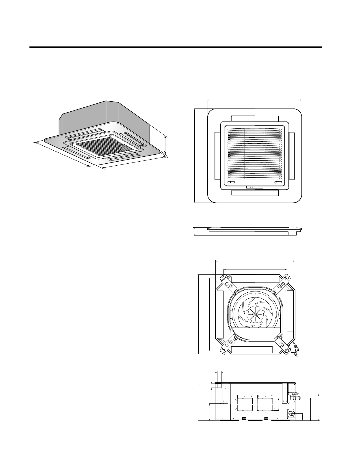
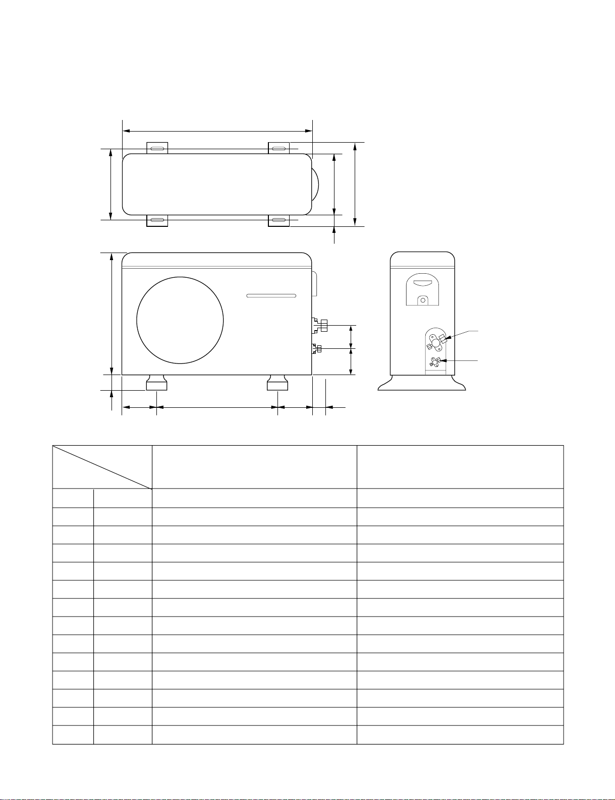
Compact and light design •To install a unit is very convenient because of smaller size
than textile. ( 600 x 600 )
Low noise •The most advanced low-noise design.
•The adoption of turbo fan and round type heat exchanger
give the quietest operation.
Long life filter •Long life wrinkle(type) and washable and anti-bacteria filter
is adopted.
Plasma Air Purifying Filter(RJ/FJ Only)
High head Drain pump •Built-in drain pump automatically drains water.
•A standard drain-head height of up to 700mm is possible.
High-Ceiling corresponding Function •According to the height of ceiling, the RPM of indoor fan
motor is selected to increase air reaching distance.
Central Control(Optional) •
It is operating individually or totally by central control function.
Group Control(Optional Wiring) •
Each controller can control 16 units and 8 controllers can be
connected.
•
It operates maximum 16 units by only one wired remote con-
troller and each unit starts sequentially to prevent overcurrent.
•Room temperature sensor. (Thermistor)
•
Maintains the room temperature in accordance with the Setting Temp.
•Indoor fan is delayed for 5 seconds at the starting.
•Restarting is inhibited for approx. 3 minutes.
•Jet, High, Med, Low
•Intermittent operation of fan at low speed.
•The louver can be set at swing up and down automatically.
•Although the air-conditioner is turned off by a power failure, it is restarted automati-
cally previous operation mode after power supply.
•The setting temperature and desired operation mode are auto-
matically set by fuzzy logic.
•Both the indoor and outdoor fan stops during defrosting.
•Hot start after defrost ends.

–5–
Remote Controller
Operation ON/OFF
Operation Mode Selection
Fan Speed Selection
Room Temperature Display
Temperature Setting
Setting the Timer
Weekly Program
(Cooling
model only) (Heating
model only)
(Low) (Med) (High)
Cooling Operation Mode ( )
Heating Operation Mode ( ) Auto Operation Mode ( )
Soft Dry Operation Mode ( )
Fan Operation Mode
HI JET AUTOMEDLO
Program Holiday
SET/CLR
MinHour
Week
Timer CancelTimer Cancel
: High:39°C ↔LOW:11°C
: Fan Operates without cooling & heating
Cooling Heating
Down to 18°C
Up to 30°CDown to 16°C
Up to 30°C

Product Specifications (Cooling & Heating)
–6–
Model
1, 220-240, 50 1, 220-240, 50
4,536(5,274) 5,872(6,892)
18,000 23,300
4,536(5,274) -
18,000 24,000
2,000 2,900
2,000 3,350
9.0 12.5
9.0 14.8
2.64 2.35
2.64 2.1
13 20
50 56
1.9 3
OO
OO
44
OO
OO
OO
OO
OO
44
OO
OO
OO
OO
OO
OO
Optional Optional
OO
O / X O / X
1,330 1,600
570 x 570 x 269 840 x 840 x 288
670 x 670 x 30 950 x 950 x 30
870 x 655 x 320 870 x 800 x 320
19 19
61 60
14 : 3*2.5 14 : 3*2.5
18 : 6*0.75 18 : 6*0.75
1/4 (6.35mm) 1/4 (6.35mm)
1/2 (12.7mm) 5/8 (15.88mm)
Ø25/32 Ø25/32
LT-E1860RJ
LT-E1860RH LT-E2460RJ
LT-E2460RH
Power Supply ø, V, Hz
Capacity Cooling kcal/h(W)
Btu/h
Heating kcal/h(W)
Btu/h
Input Cooling W
Heating W
Running Current Cooling A
Heating A
E. E. R W/W
C.O.P W/W
Air Circulation Indoor m3/min
Outdoor m3/min
Moisture Removal / h
Air-Flow Direction Control
Heating Operation Mode
Fan Speeds (steps)
Auto Operation (Changeover)
Forced Operation
Jet Cool
Soft Dry Operation
Timer Delay Safety Function
Feature Air Deflection (Way)
Self Diagnosis
Hot start
Auto Restart
Air refresh (Hole)
High Ceiling
Group Control (Optional wiring)
Central Control
Wired remote controller (with weekly Program)
Plasma A/Cleaner
Refrigerant(R-407C) Charge g
Dimensions Indoor mm
(W x D x H) Panel mm
Outdoor mm
Net Weight Indoor kg
Outdoor kg
Main Power Cord AWG#:P*mm2
Connection Cable AWG#:P*mm2
Service Valve Liquid (inch)
Gas (inch)
Drain Hose(I.D/O.D) mm

–7–
Model
3, 380-415, 50 3, 380-415, 50 3, 380-415, 50 3, 380-415, 50
9,073(10,550) 9,073(10,550) 12,096(14,065) 12,096(14,065)
36,000 36,000 48,000 48,000
9,073(10,500) - 12,096(14,065) -
36,000 - 48,000 -
4,200 4,200 4,900 4,900
3,450 - 4,400 -
6.8 6.8 8.5 8.5
6.0 - 8.0 -
2.51 2.51 2.87 2.87
3.05 - 3.20 -
25 25 30 30
68 68 105 105
1.9 1.9 3.0 3.0
OOOO
OXOX
4444
OOOO
OOOO
OOOO
OOOO
OOOO
4444
OOOO
OXOX
OOOO
OOOO
OOOO
OOOO
Optional Optional Optional Optional
OOOO
O / X X O / X X
2,480 2,200 4,200 3,400
840 x 840 x 288 840 x 840 x 288 840 x 840 x 288 840 x 840 x 288
950 x 950 x 30 950 x 950 x 30 950 x 950 x 30 950 x 950 x 30
870 x 800 x 320 870 x 800 x 320 900 x 370 x 1225 900 x 370 x 1225
32 32 32 32
81 81 95 95
14 : 3*2.5 14 : 3*2.5 14 : 3*2.5 14 : 3*2.5
18 : 6*0.75 18 : 4*0.75 18 : 6*0.75 18 : 4*0.75
1/4 (6.35mm) 1/4 (6.35mm) 3/8 (9.52mm) 3/8 (9.52mm)
5/8 (15.88mm) 5/8 (15.88mm) 3/4 (19.05mm) 3/4 (19.05mm)
Ø25/32 Ø25/32 Ø25/32 Ø25/32
LT-D3680RJ
LT-D3680RH LT-D3680FJ
LT-D3680FH LT-D4880RJ
LT-D4880RH LT-D4880FJ
LT-D4880FH
Power Supply ø, V, Hz
Capacity Cooling kcal/h(W)
Btu/h
Heating kcal/h(W)
Btu/h
Input Cooling W
Heating W
Running Current Cooling A
Heating A
E. E. R W/W
C.O.P W/W
Air Circulation Indoor m3/min
Outdoor m3/min
Moisture Removal / h
Air-Flow Direction Control
Heating Operation Mode
Fan Speeds (steps)
Auto Operation (Changeover)
Forced Operation
Jet Cool
Soft Dry Operation
Timer Delay Safety Function
Feature Air Deflection (Way)
Self Diagnosis
Hot start
Auto Restart
Air refresh (Hole)
High Ceiling
Group Control (Optional wiring)
Central Control
Wired remote controller (with weekly Program)
Plasma A/Cleaner
Refrigerant(R-407C) Charge g
Dimensions Indoor mm
(W x D x H) Panel mm
Outdoor mm
Net Weight Indoor kg
Outdoor kg
Main Power Cord AWG#:P*mm2
Connection Cable AWG#:P*mm2
Service Valve Liquid (inch)
Gas (inch)
Drain Hose(I.D/O.D) mm

Dimensions
–8–
269
67055
570
269
190.5
160
52
90
90
120.4 30 521
670
570
450
40
110 110
670
670
CLOSE OPEN OPEN CLOSE
(1) Indoor Unit
• Model : LT-E1860RJ/RH, LT-E2460RJ/RH

–9–
290
950
950
950
950
290
210.5
180
52
140
40
110
30
90
90
110
55
840
785
840
678
• Model : LT-D3680RJ/RH, LT-D3680FJ/FH
LT-D4880RJ/RH, LT-D4880FJ/FH

(2) Outdoor Unit
• Model : LT-E1860RJ/RH, LT-E2460RJ/RH
LT-D3680RJ/RH, LT-D3680FJ/FH
–10–
Gas side
3-way valve
Liquid side
2(3)-way valve
W
L6L7 L8 L9
L4
L11
L10
D
L1
L2
L5 L3
MODEL
DIM
W mm 870 870
H mm 655 800
D mm 320 320
L1 mm 370 370
L2 mm 25 25
L3 mm 340 340
L4 mm 630 630
L5 mm 25 25
L6 mm 546 546
L7 mm 162 162
L8 mm 162 162
L9 mm 54 54
L10 mm 74.5 74.5
L11 mm 79 79
LT-E1860RJ/RH
LT-E2460RJ/RH LT-D3680RJ/RH
LT-D3680FJ/FH

–11–
L6L7 L8 L9
L4
H
L11
L10
L5
W
D
L1
L2
L3
Gas side
3-way valve
Liquid side
3-way valve
Model
Dimension
W mm 900
H mm 1225
D mm 370
L1 mm 460
L2 mm 45
L3 mm 410
L4 mm 1135
L5 mm 90
L6 mm 550
L7 mm 175
L8 mm 175
L9 mm 112
L10 mm 120
L11 mm 83
LT-D4880RJ/RH
LT-D4880FJ/FH
• Model : LT-D4880RJ/RH, LT-D4880FJ/FH

Refrigeration Cycle Diagram
• HEAT PUMP
• COOLING ONLY
–12–
INDOOR UNIT
18K/24K
36K/48K
36K/48K
H/EX Liquid SideLiquid SideGas Side
COMPRESSOR
VALVE REVERSING
H/EX
Gas SideGas SideLiquid Side
CAPI
CAPI
Heating Cooling
OUTDOOR UNIT
INDOOR UNIT
H/EX Liquid SideLiquid SideGas Side
COMPRESSOR
VALVE REVERSING
H/EX
Gas SideGas SideLiquid Side
CAPI
CAPI
Heating Cooling
OUTDOOR UNIT
INDOOR UNIT
H/EX
Liquid SideLiquid SideLiquid Side
COMPRESSOR
H/EX
Gas SideGas SideGas Side
CAPI
CAPI
OUTDOOR UNIT

–13–
Wiring Diagram
•HEAT PUMP
Model No.: LT-E1860RJ/RH, LT-E2460RJ/RH
Model No.: LT-D3680RJ/RH
INDOOR WIRING DIAGRAM
3854A20126K
OUTDOOR WIRING DIAGRAM
3854A20126S
INDOOR
MOTOR DRAIN
PUMP
PIPE
THERMISTOR
REMOTE
CONTROL
FLOAT S/W
CN -DISP
DISPLAY PCB
(
OPTION
)
AIR
CLEANER
H.V. ASSY
DOOR S/W
TERMINAL
BLOCK
TO OUTDOOR UNIT
BR
YL
BK
OR
BL
BL
BR
GN/YL
RD
BK
BL
GN
/
YL
COMP
4 WAY
RD
BK
WH
RD
BK
3(L)4(N)5 6 7
FUSE T3.15A
STEP
MOTOR
TEMP.
THERMISTOR
COMP
R
S
4
28
61
0
BL
BL
WH
WH
BR
BR
BL
BL
BL
RD
BL BL
BR
GN/YL
GN/YL
CAPACITOR
CAPACITOR
REVERSING
VALVE
RD
BR
RD
WIRING OF FIELD
BK
OR
TB1
OR
YL
BK
WH
BK
C
POWER
RELAY
FAN
MOTOR
FUSE 5A
FUSE 5A
POWER
INPUT
TO INDOOR UNIT
TERMINAL
BLOCK
1(L)2(N)3(L)4(N)
5678
1
2
3
4
5
6
7
8
9
Low Ambient PCB
PIPE TH
TNS NO
L1
L2 L3 L4
D.P
NC NO NC
pipe TH
TB2
REMOVE JUMP WIRE
WHEN CONNECTING
FIRE ALARM SYSTEM
INDOOR WIRING DIAGRAM
OUTDOOR WIRING DIAGRAM
INDOOR
MOTOR DRAIN
PUMP STEP
MOTOR
PIPE
THERMISTOR
REMOTE
CONTROL
FLOAT S/W
CN -DISP
DISPLAY PCB
AIR
CLEANER
H.V. ASSY
DOOR S/W
TERMINAL
BLOCK
TO OUTDOOR UNIT
3854A20072G
BR
YL
BK
OR
BL
BL
BR
GN/YL
RD
BK
BL
GN
/
YL
COMP
RD
BK
WH
RD
BK
12345
FUSE T3.15A
4 WAY
(
OPTIONAL EXTRA
)
TEMP.
THERMISTOR
3854A20126X
CM
52C
T1
2
1
4
3
632
A
B
31
5
T2 T3
BL
BL
BL
BL
BK
BK
WH
PIPE.TH
BKBK
BK BK
GN/YL
20SV
20SV
52C
63H
Co
CH
C TH
DP
FUSE
FMo
CM
REVERSING COIL
MAGNECTICONTACTOR
HIGH PRESSURE SWITCH FOR HEATING
RUN CAPCCITOR FOR FMo
CRANK CASE HEATER FOR CM
THERMISTOR FOR PIPETEMP.
DEICER PCB
250V, 5A
OUTDOOR FAN MOTOR
COMPRESSOR
TMo
C TH
TNS
NO NONC NC
T/B1
T/B2
D.P
BK
OR
Co
OR
OR OR
BK
BK
R
3Ø, 50Hz
380-415V
POWER SUPPLY
To the indoor unit
WIRING OF FIELD
(CONNECTING WIRE)
STN
1(L) 2(N) 3 4 5
BKBK
BL
BK
WH
WH
WH
WH
WH
WH
RD
YL
RD
RD 1
2
3
4
LOW AMBIENT CIRKIT
5
6
7
8
9
RD
FMo
WH
REMOVE JUMP WIRE
WHEN CONNECTING
FIRE ALARM SYSTEM

–14–
Model No.: LT-D4880RJ/RH
INDOOR WIRING DIAGRAM
3854A20072G
OUTDOOR WIRING DIAGRAM
3854A20126Y
INDOOR
MOTOR DRAIN
PUMP STEP
MOTOR
PIPE
THERMISTOR
REMOTE
CONTROL
FLOAT S/W
CN -DISP
DISPLAY PCB
AIR
CLEANER
H.V. ASSY
DOOR S/W
TERMINAL
BLOCK
TO OUTDOOR UNIT
BR
YL
BK
OR
BL
BL
BR
GN/YL
RD
BK
BL
GN
/
YL
COMP
RD
BK
WH
RD
BK
3(L) 4(N) 5 6 7
FUSE T3.15A
4 WAY
(
OPTIONAL EXTRA
)
TEMP.
THERMISTOR
R
POWER SUPPLY
MAGNETIC
CONTACTER
CRANK-CASE
HEATER
STN
BK
BK BK
BK
BK
WH
WH
WH WH
RD
BK
BL
WH
D.P
TNS NONO
pipe TH
NCNC
WH OR
WH
BK
BK
OR
BK
BK
BK
WH
POWER
RELAY
1
2
3
4
5
6
31
T/B3
T/B2
T/B1
32
B
A
FAN
MOTOR FAN
MOTOR
YL BK
OR
BK
T3 T2 T1
RD
BK
WH
COMP.
12
34
56
78
YL BK
OR
OR
BK
BK
BL
BL
BK WH
CAPACITOR CAPACITOR
REVERSING
VALVE
BR
BL
BR
BL
GN/YL
GN/YL
TERMINAL BLOCK
To the indoor unit
1
2
3
4
5
6
1
2
3
4
5
6
7
8
9
BK
WHWH BL
Fuse
(250V 5A)
Fuse
(250V 5A)
BK
BK
BK
PIPE TH
Low Ambient PCB
REMOVE JUMP WIRE
WHEN CONNECTING
FIRE ALARM SYSTEM
FUSE T3.15A
TRIAC

•COOLING ONLY
Model No.: LT-D3680FJ/FH
Model No.: LT-D4880FJ/FH
–15–
INDOOR WIRING DIAGRAM
OUTDOOR WIRING DIAGRAM
3854A20072J 3854A30079F
INDOOR
MOTOR DRAIN
PUMP STEP
MOTOR
TEMP.
THERMISTOR
PIPE
THERMISTOR
REMOTE
CONTROL
FLOAT S/W
CN -DISP
DISPLAY PCB
OPTION
AIR
CLEANER
H.V. ASSY
DOOR S/W
TERMINAL
BLOCK
TO OUTDOOR UNIT
BR
YL
BK
OR
BL
BL
BR
GN/YL
RD
BL
GN
/
YL
COMP
BK
RD
WH
RD
BK
1 2 3 4 5
FUSE T3.15A
CM
OR BK
CM
52C
CH
Co
TMo
C TH
FMo
FUSE
TB
THERMISTOR FOR PIPE TEMP.
OUTDOOR FAN MOTOR
250V, 5A
TERMINAL BLOCK(FOR JUMP)
COMPRESSOR
MAGNECTIC CONTACOR
CRANK CASE HEATER FOR CM
RUN CAPACITOR FOR FMo
TERMINAL BLOCK(FOR POWER)
OR
Co
RD
1
2
3
4
5
6
7
8
9
WH
BK
BL
LOW AMBIENT KIT
PIPE. TH
WH
WH
T3
T2
T1
2
1
4632
A
B
31
35
52C
FUSE
R S T N 1(L) 3 4 5
GN/YL
To the indoor unit
3Ø, 50Hz
380-415V
POWER SUPPLY
WIRING OF FIELD
(CONNECTING WIRE)
TMo
TB
2(N)
BK
BKBK
BK
RD
RD
YL
WH
WH
WH
WH
FMo
INDOOR WIRING DIAGRAM
OUTDOOR WIRING DIAGRAM
3854A20077F3854AP20072J
INDOOR
MOTOR DRAIN
PUMP STEP
MOTOR
TEMP.
THERMISTOR
PIPE
THERMISTOR
REMOTE
CONTROL
FLOAT S/W
CN -DISP
DISPLAY PCB
OPTION
AIR
CLEANER
H.V. ASSY
DOOR S/W
TERMINAL
BLOCK
TO OUTDOOR UNIT
BR
YL
BK
OR
BL
BL
BR
GN/YL
RD
BL
GN
/
YL
COMP
BK
RD
WH
RD
BK
1 2 3 4 5
FUSE T3.15A
GN/YL TMo
To the indoor unit Low Ambient PCB
2(N)
1(L)
3
4
5
F1
F1
RTM
POWER SUPPLY
STN
BK
BK
WH
RD
WH WH
52C 1
2
3
4
5
6
31
32
B
A
FMo
49FMo FMo
49FMo
BK
T3 T2 T1
RD
WH BK
BL
WH
WH
CM
YL BK
OR
Co Co
TB
YL
OR BK
BR
BK
OR
OR
BR
1
2
3
4
5
6
7
8
9
PIPE TH

–16–
Operation Details
(1) The function of main control
1. Time Delay Safety Control
•3min The compressor is ceased for 3minutes to balance the pressure in the refrigeration cycle.
(Protection of compressor)
•5sec
Vertical louvers are delayed for 5 secs to be opened to prevent the frictional sound between louver and air flow.
•30sec The 4-way valve is ceased for 30sec. to prevent abnormal noise when the Heating operation is OFF or
switched to the other operation mode while compress is off.
While compressor is running, it takes 3~5 seconds to switch.
2. Auto Swing Control
•This function is to swing the louver up and down automatically.
3. Air-Filter Checking Control
•'Filter' sign will appear on the remote controller display and main body display when an air-filter is polluted. Then
clean the air-filter referring to Owners Manual.
4. Soft-Dry Operation
•The indoor fan speed is automatically set to the low, and fan speed control is not available because of already
being set to the best speed for Dry Operation by Micom Control.
5. Cooling Mode Operation
•When selecting the Cooling( ) Mode Operation, the unit will operate according to the setting by the remote con-
troller and the operation diagram is as follows.
Intake Air temp.
SET TEMP.+0.5°C
(COMP. ON)
SET TEMP
SET TEMP. -0.5°C
(COMP. OFF)
Selected Selected Selected
fan speed fan speed fan speed
COMPRESSOR ON OFF ON OFF ON
INDOOR FAN Low Low
More than
3 minutes
More than
3 minutes

–17–
Intake Air temp.
Setting temp.+3°C
(Compressor OFF)
Setting temp.
(Compressor ON)
INDOOR FAN
COMPRESSOR ON OFF ON OFF
A point; While the indoor Heat-Exchanger temperature is higher than 40°C fan operates at low speed, when
it becomes lower than 40˚C fan stops.
B point; When the indoor Heat-Exchanger temperature is higher than 42°C, fan operates at selected fan
speed, when it becomes lower than 39°C, the fan operates at low speed.
6. Heating Mode Operation
The unit will operate according to the setting by the remote controller and the operation diagram is shown as follows.
(Hot Start)
Low
OFF
Selected
Fan Speed
minimum 3min
Selecting fan
speed
LowLowLow OFF OFF
minimum
10sec.
1min
AA
minimum
1min.
minimum
10sec.
B
7. Hot-Start Control
•The indoor fan stops until the evaporator piping temperature reaches to 25°C.
•If the evaporator piping temperature drops below 22°C, indoor fan stops again.
•The operation diagram is as follows.
PIPING
TEMPERATURE 1min
COMPRESSOR
INDOOR FAN
ON
OFF LOW Selected
fan speed
22°C
25°C

–18–
8. Defrost Control
•Defrost control is available 45 minutes later since heating mode operation started, and it will not prolong over
10 minutes.
•Defrost control is carried out when the outdoor pipe temp. falls below -6°C for more than 3 minutes after 45
minutes passed from starting of heating operation.
•Defrost ends after 10 minutes passed from starting of defrost operation or when the outdoor pipe temp. rises
over 12°C after 5 minutes passed from starting of defrost.
More than 45 minutes
of heating operation Within
9min. 45sec.
ON OFF
ON
ON
ON OFF
COMPRESSOR
4-WAY VALVE
INDOOR FAN
-6°C ON
12°C OFF
The outdoor
piping Temp. More than 10 min.
running of compressor
More than 45 minutes
of heating operation
HOT-
START
ON
■Defrost Control (New Type Defrost Control)
•While in heating mode operation in order to protect the evaporator pipe of the outdoor unit from freezing, reversed to
cooling cycle to defrost the evaporator pipe of the outdoor unit.
•Defrost control is available 45 min. later since heating mode operation started, and it will not prolong over 10 min.
•Defrost control is carried out according to the following priority order while in heating mode operation.
1st priority : Defrost control is carried out according to the indoor pipe temp 60 min. later since heating mode opera-
tion started.
2nd priority : The temp differences between the indoor pipe temp and the intake air temp 25 min. later(∆T1) and 45
min. later (∆T2) since heating mode operation started are measured, then defrost control is carried out
according to the dirrerence (∆T=∆T1-∆T2)
3rd priority : Defrost control is carried out according to the temp difference (E=TE1-TE2) between the indoor pipe
temperatures of 25 min later(TE1) and 45 min later (TE2) after heating mode operation started.
•When the indoor pipe temp is 41°C or above, defrost control is not carried out even if the condition is one of the
defrost conditions above.
•While in defrost control, the compressor is on and the indoor fan, the outdoor fan, and the 4 way valve are off.
9. Self-diagnosis Function
•'CHECK' will flash in the remote controller display when a problem occurs.
•Correct the 'FAULT MESSAGES' as shown in the table below before restarting operation.
•During the normal operation 'CHECK' won't be displayed in the remote controller.
Remote controller LCD FAULT MESSAGES
CH 01 Indoor room temperature thermistor error
CH 02 Indoor piping thermistor error
CH 03
Indoor main body / Remote controller unit communication error
CH 04 Water level float switch error

–19–
Installation of Indoor, Outdoor Unit
1. Selection of the best location
1) Indoor unit
•There should not be any heat source or steam
near the unit.
•There should not be any obstacles to the air cir-
culation.
•A place where air circulation in the room will be
good.
•A place where drainage can be easily obtained.
•A place where noise prevention is taken into con-
sideration.
•Do not install the unit near the door way.
•Ensure the spaces indicated by arrows from the
wall, ceiling, or other obstacles.
•The indoor unit must have the maintenance
space around.
2) Outdoor unit
•If an awning is built over the unit to prevent direct
sunlight or rain exposure, be careful that heat
radiation from the condenser is not restricted.
•There should not be any animals or plants which
could be affected by hot air discharged.
•Ensure the spaces indicated by arrows from the
wall, ceiling, fence or other obstacles.
More than
30cm
Sunroof
Fence or
obstacles
More than 70cm
More than 50cm
More than
30cm
More than
30cm
Unit:cm
Ceiling
Ceiling Board Ceiling Board
30 or more
Above 250
330 or less
100
or more
50 or
more
50 or
more
30 or less
Floor

–20–
NOTE:
•Avoid the following installation location.
1. Such places as restaurants and kitchen where considerable amount of oil steam and flour is generated.
These may cause heat exchange efficiency reduction, or water drops, drain pump mal-function.
In these cases, take the following actions;
•Make sure that ventilation fan is enough to cover all noxious gases from this place.
•Ensure enough distance from the cooking room to install the air conditioner in such a place where it may
not suck oily steam.
2. Avoid installng air conditioner in such places where cooking oil or iron powder is generated.
3. Avoid places where inflammable gas is generated.
4. Avoid place where noxious gas is generated.
5. Avoid places near high frequency generators.
2. Ceiling opening dimensions and hanging bolt location
•The dimensions of the paper model for installing are the same as those of the ceiling opening dimensions.
•Select and mark the position for fixing bolts and piping hole.
•Decide the position for fixing bolts slightly tilted to the drain direc-
tion after considering the direction of drain hose.
•Drill the hole for anchor bolt on the wall.
•This air-conditioner uses a drain pump.
•Install the unit horizontally using a level gauge.
•During the installation, care should be taken not to
damage electric wires.
CAUTION
Level gauge
Ceiling
Unit:mm
570 Unit size
570 Unit size
450 (Hanging bolt)
7575
600 (Ceiling opening)
521(Hanging bolt) 39.5
39.5
Unit:mm
840 Unit size
840 Unit size
672 (Hanging bolt)
101.5101.5
875 (Ceiling opening)
785(Hanging bolt) 45
45
Ceiling board
Use the ventilation fan
for smoke-collecting
hood with sufficient
capacity.
Cooking table
Air conditioner
Take enough
distance
18K/24K
36K/48K
This manual suits for next models
10
Table of contents
Other LG Air Conditioner manuals

LG
LG Multi V CRUN Series User manual

LG
LG LF300CP(LP-C303R20), LF480CE(L User manual

LG
LG LV-B1860RL User manual

LG
LG APNQ55GT3E0 User manual

LG
LG G122C SR2 User manual

LG
LG LS243HLV3 Installation and operation manual

LG
LG MULTI V ARNU363DDB4 User manual

LG
LG AUUW09GA0 Product guide

LG
LG SP091CN User manual

LG
LG LP1111WXR User manual