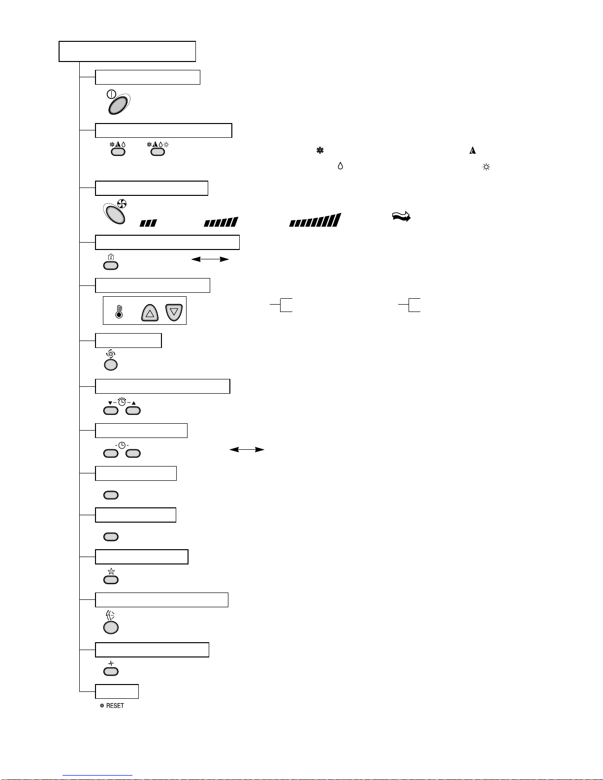
LG LM-2561C3L User manual

Multi Type Room
Air Conditioner
SERVICE MANUAL
MODEL: LM-2561C3L
LM-2860C5L
LM-3060H4L/M
LM-4260H3L/M

Functions...................................................................................................................................... 3
Product Specifications................................................................................................................ 5
Dimensions................................................................................................................................. 10
Refrigeration Cycle Diagram..................................................................................................... 13
Wiring Diagram .......................................................................................................................... 17
Operation Details ....................................................................................................................... 19
Display Function........................................................................................................................ 26
Self-diagnosis Function ............................................................................................................ 26
Installation.................................................................................................................................. 27
Operation.................................................................................................................................... 41
Disassembly of the parts (Indoor Unit).................................................................................... 43
2-way, 3-way Valve ..................................................................................................................... 45
Cycle Troubleshooting Guide ....................................................................................................49
Electronic Parts Troubleshooting Guide.................................................................................. 50
Electronic Control Device ......................................................................................................... 57
Schematic Diagram.................................................................................................................... 61
Exploded View and Replacement Parts List............................................................................ 64
- 2 -
Contents

- 3 -
Functions
• Room temperature sensor. (THERMISTOR)
• Maintains the room temperature in accordance with the Setting Temp.
• Indoor fan is delayed for 5 seconds at the starting.
• Restarting is inhibited for approx. 3 minutes.
• High, Med, Low, Chaos
--- Lights up in operation
--- Lights up in Sleep Mode
--- Lights up in Timer Mode
--- Lights up in Deice Mode(for Heat pump model)
--- Lights up in Compressor operation(for Cooling model)
• Intermittent operation of fan at low speed.
• The fan is switched to low(Cooling), med(Heating) speed.
• The unit will be stopped after 1, 2, 3, 4, 5, 6, 7 hours.
• The fan is switched to intermittent or irregular operation
•
The fan speed is automatically switched from high to low speed.
• The louver can be set at the desired position or swing
up and down automatically.
Indoor Unit
Operation ON/OFF by Remote controller
Sensing the Room Temperature
Room temperature control
Starting Current Control
Time Delay Safety Control
Indoor Fan Speed Control
Operation indication Lamps (LED)
OUT
DOOR
Health Dehumidification Operation
• Both the indoor and outdoor fan
stops during deicing.
• Hot start after deice ends.
• The indoor fan stops until the
evaporator piping temperature will be
reached at 22°C.
Sleep Mode Auto Control
Natural Air Control by CHAOS Logic
Airflow Direction Control
Deice (defrost) control (Heating)
Hot-start Control (Heating)

- 4 -
Remote Controller
JET COOL
Healthy Dehumidification Operation Mode.
( )
Operation Mode Selection
(Cooling
model only) (Heating
model only)
Cooling Operation Mode.( ) Heating Operation Mode.( )
Auto Operation Mode.( )
Sleep Operation
Fan Operation Mode
Room, Temperature Display
Setting the Time or Timer
Airflow Direction Control
Operation ON/OFF
Temperature Setting
TEMPERATURE LOWHIGH
Timer Selection
ON OFF
Timer Setting
SET
Timer Cancel
CANCEL
Reset
Fan Speed Selection
(Low) (Med) (High) (CHAOS)
: (High: 39°C LOW : 11°C)
Down to 18°C
Up to 30°C
Cooling
: OFF, ON, OFF ON
: Cancel Sleep Mode, Timer ON or Timer OFF
: 1, 2, 3, 4, 5, 6, 7, Off Timer
: Fan Operates without cooling or heating.
Down to 16°C
Up to 30°C
Heating

- 5 -
Product Specifications
1. LM-2561C3L
10,000(2,512) 10,000(2,512) 20,000(5,025) 15,000(3,769)
25,000(6,281)
1.4 1.4 2.8 2.1 3.5
1Ø, 230V, 50Hz
8.6 7.0 - - -
53 - - -
36 + 1 34 + 1 - - -
55 + 1
1080 1,300 2,250 - 2,400
5.1 6.1 10.5 - 10.9
8.33 10.4 7.29 - 10.0
13 7.5 - - -
61
888 x 284 x 170 802 x 262 x 165 - - -
870 x 655 x 320
10 7 - - -
61
985 1,300 - - -
O
L.C.D Wireless
1/4"(6.35) - - -
3/8"(9.52) - - -
O
O
Operation A-Unit
B or C-Unit
A+B or C B+C A+B+C
Unit
Item
Cooling Capacity Btu/h(kcal/h)
Moisture Removal l/h
Power Source ø, V, Hz
Air Circulation m3/min Indoor
Outdoor
Noise Level dB(A) Indoor
Outdoor
Input W
Runnig Current A
E.E.R. Btu/h.w
Motor Output W Indoor
Outdoor
Dimensions(W x H x D)
mm Indoor
Outdoor
Net. Weight kg Indoor
Outdoor
Refrigerant(R-22)(at 7.5m)
g
Airflow Direction Control(Up & Down)
Remocon Type
Service Valve Liquid
Gas
Sleeping Operation
Drain Hose

- 6 -
2. LM-2860C5L
11,000 8,500 14,000 19,500 12,400 13,500
2,772 2,142 3,528 4,914 3,125 3,402
1.6 1.2 2.0 2.8 1.8 1.9
1Ø, 230V, 50Hz
7.0
58
38
57
1,120 1,020 1,220 2,190 1,130 1,150
5.0 4.5 5.4 9.2 5.0 5.1
9.8 8.3 11.5 8.9 11.0 11.7
8
102
802 x 262 x 165
870 x 800 x 320
7
83
1,110 1,600
O
L.C.D Wireless
1/4"(6.35)
3/8"(9.52)
O
O
Operation A1 or A2 B1 or B2
or B3 A1 + A2 A1 or
A2+B1 or
B2 or B3
B1+B2 or
B3 B1+B2+
B3
Unit
Item
Cooling Capacity Btu/h
kcal/h
Moisture Removal l/h
Power Source ø, V, Hz
Air Circulation m3/min Indoor
Outdoor
Noise Level dB(A) Indoor
Outdoor
Input W
Runnig Current A
E.E.R. Btu/h.w
Motor Output W Indoor
Outdoor
Dimensions(W x H x D)
mm Indoor
Outdoor
Net. Weight kg Indoor
Outdoor
Refrigerant(R-22)(at 7.5m)
g
Airflow Direction Control(Up & Down)
Remocon Type
Service Valve Liquid
Gas
Sleeping Operation
Drain Hose

- 7 -
23,400 22,500 24,500 26,400 27,500
5,897 5,670 6,174 6,653 6,930
3.3 3.2 3.5 3.7 3.9
1Ø, 230V, 50Hz
7.0
58
38
57
2200 2220 2270 2300 2320
9.7 9.6 9.8 10.1 10.2
10.6 10.1 10.8 11.5 11.9
8
102
802 x 262 x 165
870 x 800 x 320
7
83
O
L.C.D Wireless
1/4"(6.35)
3/8"(9.52)
O
O
Operation A1 or
A2+B1+B2
or B3
A1 or
A2+B1 or
B2 or B3
A1 or
A2+B1+B2+
B3
A1+A2+B1+
B2 or B3 A1+A2+B1+
B2+B3
Unit
Item
Cooling Capacity Btu/h
kcal/h
Moisture Removal l/h
Power Source ø, V, Hz
Air Circulation m3/min Indoor
Outdoor
Noise Level dB(A) Indoor
Outdoor
Input W
Runnig Current A
E.E.R. Btu/h.w
Motor Output W Indoor
Outdoor
Dimensions(W x H x D)
mm Indoor
Outdoor
Net. Weight kg Indoor
Outdoor
Refrigerant(R-22)(at 7.5m)
g
Airflow Direction Control(Up & Down)
Remocon Type
Service Valve Liquid
Gas
Sleeping Operation
Drain Hose

- 8 -
14,000(3,527)
8,000(2,015) 8,000(2,015)
18,000(4,535) 12,000(3,023) 30,000(7,559)
14,000(3,527)
9,000(2,267) 9,000(2,267)
18,000(4,535) 12,000(3,023) 30,000(7,559
1.7 1.2 1.2 2.9 2.4 5.3
1Ø, 220-240V, 50Hz
9.0 7.0 7.0 –––
58 –––
35 33 33 –––
58
1,850 1,700 1,300 1,990 1,440 3,300
2,000 2,350 1,570 1,790 1,150 2,800
8.1 7.5 5.8 8.9 6.4 14.5
8.9 10.4 7.0 8.0 5.1 12.5
7.5 4.7 6.1 9.0 8.3 9.1
1.7 1.0 1.4 2.5 2.6 2.7
13 7.5 7.5 –––
101.5
888x287x170
802 x 262 x 165 –––
870 x 800 x 320
10 7 7 –––
88
1,720 1,200 –––
O
L.C.D Wireless
1/4"(6.35) 1/4"(6.35) 1/4"(6.35) –––
1/2"(12.7) 3/8"(9.52) 3/8"(9.52) –––
O
O
Operation A1-unit
A2 -unit B1 or
B2-unit A1+A2 B1+B2 A1+A2+
B1+B2
Unit
Item
Cooling Capacity
Heating Capacity
Moisture Removal l/h
Power Source ø, V, Hz
Air Circulation m3/min
Noise Level dB(A)
Input W
A
E.E.R. Btu/h.w
C.O.P. -
Motor Output W
Dimensions(W x H x D)
mm
Net. Weight kg
Refrigerant(R-22)(at 7.5m)
g
Airflow Direction Control(Up & Down)
Remocon Type
Service Valve
Sleeping Operation
Drain Hose
Cooling
Heating
Indoor
Outdoor
Indoor
Outdoor
Indoor
Outdoor
Indoor
Outdoor
Indoor
Outdoor
Liquid
Gas
Cooling
Heating
Cooling
Heating
Runnig
Current
Btu/h(kcal/h)
3. LM-3060H4L/M

- 9 -
18,000(4,536)
15,500(3,906) 33,500(8,443) 23,000(5,796) 41,000(10,333)
18,000(4,536)
15,500(3,906) 33,500(8,443) 24,000(6,048) 42,000(10,585)
2.5 2.2 4.8 3.4 6.5
1Ø, 220-240V, 50Hz
12.5 8.5 –––
106 –––
42 40 –––
65
1,950 2,250 3,850 2,450 4,150
2,050 2,950 4,700 2,350 4,150
8.5 10.0 17.2 10.9 18.2
9.0 13.0 20.9 11.0 18.2
9.2 6.9 8.7 9.4 9.9
2.6 1.5 2.1 3.0 3.0
22 13
80 x 2
1180 x 314 x 181
888
x 287 x 170
1225 x 900 x 370
11 9 –––
106
1,920 2,250 –––
O
L.C.D Wireless
1/4"(6.35) –––
1/2"(12.7) 1/2"(12.7) –––
O
O
Operation A-Unit
B or C-Unit A+B or C
B+C A+B+C
Unit
Item
Cooling Capacity
Heating Capacity
Moisture Removal l/h
Power Source ø, V, Hz
Air Circulation m3/min
Noise Level dB(A)
Input W
A
E.E.R. Btu/h.w
C.O.P. -
Motor Output W
Dimensions(W x H x D)
mm
Net. Weight kg
Refrigerant(R-22)(at 7.5m)
g
Airflow Direction Control(Up & Down)
Remocon Type
Service Valve
Sleeping Operation
Drain Hose
Cooling
Heating
Indoor
Outdoor
Indoor
Outdoor
Indoor
Outdoor
Indoor
Outdoor
Indoor
Outdoor
Liquid
Gas
Cooling
Heating
Cooling
Heating
Runnig
Current
Btu/h(kcal/h)
4. LM-4260H3L/M

1. Indoor Unit
- 10 -
Dimensions
Installation plate
Installation plate
Right rear piping
Left rear piping
ø70mm ø70mm
50mm
20mm
20mm
80mm
A
A
ø70mm
Center
Center
ø70mm
Left rear piping Right rear piping
A
A
D
H
W
Tubing hole cover
W mm 802 888 1,080
H mm 262 287 314
D mm 165 170 181
4.5K, 6K, 7K, 8K, 9K
Btu Series 9K, 10K, 12K Btu
Series 18K Btu
MODEL
DIM
( 4.5K, 6K, 7K, 8K, 9K )
( 9K, 10K, 12K, 18K )

- 11 -
W
D
L1
L2
L9
L4 L3
H
L10L10L10
L8
Gas side
3-Way valve
Liquid side
2-Way valve
L7L5L6
2. Outdoor Unit
W mm 870 870
H mm 655 800
D mm 320 320
L1 mm 370 370
L2 mm 25 25
L3 mm 630 775
L4 mm 25 25
L5 mm 546 546
L6 mm 160 160
L7 mm 160 160
L8 mm 64 64
L9 mm 76.5 76.5
L10 mm 50 45
LM-2561C3L LM-3060H4L/M
LM-2860C5L
MODEL
DIM

- 12 -
LM-4260H3L/M
900
1,225
370

- 13 -
Refrigeration Cycle Diagram
Pipe Size (Diameter : inch)
Max.
piping length
(m)
Max.
piping elevation
(m)
Gas Liquid
3/8"(1/2") 1/4" 10~15 5~7
ex) Solenoid Valve
Capillary
Cooling & Deice
Heating
Indoor Unit Outdoor Unit
Heat
Exchanger
A-Unit
Heat
Exchanger
Comp-A
Comp-B
B-Unit C-Unit
Heat
Exchanger
2- WAY
Valve
3- WAY
Valve
2- WAY
Valve
3- WAY
Valve
1. LM-2561C3L(Cooling only model)

- 14 -
2. LM-2860C5L/M(Cooling only model)
Pipe Size (Diameter : inch)
Max.
piping length
(m)
Max.
piping elevation
(m)
Gas Liquid
3/8" 1/4" 10~15 5~7
ex) Solenoid Valve
Capillary
Cooling & Deice
Indoor Unit Outdoor Unit
Heat
Exchanger
Heat
Exchanger
A1-Unit
B1-Unit B2-Unit B3-Unit
A2-Unit Heat
Exchanger
Comp-B
Comp-A

- 15 -
3. LM-3060H4L/M(Cooling & Heating model)
Pipe Size (Diameter : inch)
Max.
piping length
(m)
Max.
piping elevation
(m)
Gas Liquid
3/8"(1/2") 1/4" 10~15 5~7
ex) Solenoid Valve
Capillary
Cooling & Deice
Heating
Indoor Unit Outdoor Unit
Heat
Exchanger
B2-UnitB1-Unit
Heat
Exchanger
Comp-B
A1-Unit
A2-Unit
Heat
Exchanger
2- WAY
Valve
2- WAY
Valve
3- WAY
Valve
3- WAY
Valve
Comp-A

- 16 -
4. LM-4260H3L/M(Cooling & Heating model)
Pipe Size (Diameter : inch)
Max.
piping length
(m)
Max.
piping elevation
(m)
Gas Liquid
1/2" 1/4" 10~15 5~7
ex) Solenoid Valve
Capillary
Cooling & Deice
Heating
Check Valve
Indoor Unit Outdoor Unit
Heat
Exchanger
A-Unit
Heat
Exchanger
Comp-A
B-Unit
C-Unit
Heat
Exchanger
2- WAY
Valve
3- WAY
Valve
2- WAY
Valve
3- WAY
Valve Comp-B

3854A20023B
INDOOR WIRING DIAGRAM
CN-DISP1
CN-U/D
FUSE
AC250V/T2A
CN-TH
SSR
SH-CAPA.
BR
YL
OR
BK
CN-POWER CN-FAN
ZNR
THERMISTOR
FORCED
OPERATION
AUTO
RESTART
REMOTE
CONTROL
STEP
MOTOR
MOTOR
MAIN PCB
ASM
DISPLAY PCB ASM
TO OUTDOOR UNIT
PILLAR
TERMINAL
BR
BL
YL
1(L)2(N)
3
- 17 -
Wiring Diagram
1. Indoor Unit
■LM-2561C3L, LM-2860C5L, LM-3060H4L/M, LM-4260H3L/M

BK
T/B1BK
CAPA.
CAPA.
RY1
RY2
RY3
RY7
RY8
CN-TH2
CN-SV
CN-TH1
FCH
3131
BK
BK BL
BK T/B2
BL
BL BL
WH
BR
BL RD WH
GN/YL
TERMINAL
BLOCK
WH
BK
WH
BK
BK
BK
RD
BK
BK
BR
YL
YL GN/YL
OR
RD
S
S
RR
CC
BK
RD BL
CN
-
FAN
CN
-
COMP
BK
"B"
COMP "A"
COMP
MOTOR
34
7531 13
21
FUSE T3.15A
CN
-
POWERCN
-
COM
MAIN PCB ASSY
CN-TRANS
TRANS-
FORMER
B S.V
C S.V
1(L) 2(N) 3 3 2(N) 1(L) 3 1(L) 2(N)
A-UNIT B-UNIT
TO INDOOR UNIT
C-UNIT MAIN
POWER
OUTDOOR WIRING DIAGRAM 3854A30076G
T/B3
OLPOLP
MOTOR
OUTDOOR WIRING DIAGRAM
3854A20023P
MAIN PCB ASSY
TO INDOOR UNIT
B1-UNIT B2-UNIT B3-UNIT MAIN
POWER
TERMINAL
BLOCK
TERMINAL
BLOCK
CN-TRANS
BR
BL
BK BK
BK
BK
"A"
COMP
BL BK BR WH BL YL
RD
RD
SR
C
OLP
C
RBR
BK
YL
S
BK
BK
YL
OR BK
BK
T/B2 T/B3
T/B1
T/B4
BK
WH
BK
OR
YL
BK
WH
RD
WH BK
GN/YL
CN-COM
CN-TH1
CN
-
POWER
RY8
RY9
RY3
RY2
RY1
CN
-
FAN
CN-COMP
CAPA.
CAPA.
FUSE T3.15A
THERMISTOR
TRANS-
FORMER
A1-UNIT A2-UNIT
OLP
RY10
RY7
RY4
"B"
COMP
1(L) 1(L)2(N) 1(L) 2(N)2(N)
33
1(L) 2(N)
33
3
TO INDOOR UNIT
HCF
A1 S.V
A2 S.V
RD
B3 S.V
B1 S.V
B2 S.V
CN-SV
MOTOR
B/P1 S.V
OUTDOOR WIRING DIAGRAM
3854AP7050Q
MAIN PCB ASSY
TO INDOOR UNIT
A1-UNIT A2-UNIT B1-UNIT B2-UNIT MAIN
POWER
TERMINAL
BLOCK
CN-TRANS
BL
RD
BK BK BK BK
BK
BK
"A"
COMP
BL BK
BK
BK
CN-FAN
LOWHIGH
CN-BYPASS
WH
WH BL
BL
BL
WH
WH
BR
BR
RD
RD
YL
YL YL
RD
RD
SR
C
OLP
C
RBR
BK
YL
S
BK
BK
YL
OR BK
BK T/B2
T/B6
T/B3 T/B4 T/B5
T/B1
BK
WH
BKBK
WH
BR BK WH BK
CN-COM
CN-TH 1
CN
-
POWER
CN
-
COMP
CAPA.
CAPA.
FUSE T3.15A
THERMISTOR
TRANS-
FORMER
RY-SV4
RY-SV3
RY-SV2
RY-SV1
RY-BP2
RY-BP1
RY-LOW
RY-HI
RY-COMP(B)
RY-COMP(A)
RY-4WAY(A)
RY-4WAY(B)
"B"
COMP
3
2(N)
2(N)1(L)2(N)
1(L)
33 3
1(L)
HCF
A1-S.V
B/P3 S.V
B/P2 S.V
A2-S.V
B1-S.V
B2-S.V
A4-WAY
CN-4WAY
CN-SV
B4-WAY
BK BK
BK
BK
BK
BK
BK BK
BK
WH
RD YL
YL
OR OR
OR
OR
YL
YL
BL
BL BL BL
BL
BL
BK
BK
BK
BK
BL BL BL
BL
BL
YL
RD
RD
RD
BR
BR
BR
SS
CRCR
A-COMP
A-MOTOR
A - COMP
POWER RELAY
B-COMP
B-MOTOR
B - COMP
POWER RELAY
CAPA.
CAPA.
CAPA.
CAPA.
BK BK
WH
BK
GN
/
YL
GN
/
YL GN
/
YL
BK
T/B3 T/B1
T/B2
WH
WH
YL
T/B4 T/B5 T/B6
T/B7
BR
BR
WH
WH
WH
RD
RD
CN - COMP
CN - TRANS
CN - TH1 CN - TH2
RY-COMP(A)
RY-COMP(B)
RY-HI
RY-BP2
RY-SV1
RY-SV2
RY-SV3
RY-SV4
B
/
P S.V
B S.V
C S.V
A 4-WAY
B 4-WAY
TRANS-
FORMER
CN - FAN CN - BYPASS CN - SV
CN - POWER
CN - COM
THERMISTOR
THERMISTOR
MAIN PCB ASSY
POWER INPUT
1Ø, 220~240V, 50Hz
FUSE T3.15A
A - UNIT
TO INDOOR UNIT
OUTDOOR WIRING DIAGRAM
B - UNIT C - UNIT
3854A30042U
3(N)4(L)
1(L)2(N)2(N)
1(L)
33 3
43
3
321
335
711
21
1
1
1
0
10
86 42
86 42
- 18 -
1. LM-2561C3L 2. LM-2860C5L 3. LM-3060H4L/M
2. Outdoor Unit
4. LM-4260H3L

Operation Details
1. MAIN UNIT FUNCTION
• DISPLAY
1) C/O Model
Operation Indicator
•On while in appliance operation, off while in appliance pause
•Flashing while in disconnection or short in Thermistor (3 sec off / 0.5 sec on)
Sleep Timer Indicator
•On while in sleep timer mode, off when sleep timer cancel or appliance operation pause
Timer Indicator
•On while in timer mode (on/off), off when timer mode is completed or canceled.
Comp. Running Incidator
•While in appliance operation, on while in outdoor unit compressor running, off while in compressor off
2) H/P Model
Operation Indicator
•On while in appliance operation, off while in appliance pause
•Flashing while in disconnection or short in Thermistor (3 sec off / 0.5 sec on)
Sleep Timer Indicator
•On while in sleep timer mode, off when sleep timer cancel or appliance operation pause
Timer Indicator
•On while in timer mode (on/off), off when timer mode is completed or canceled
Defrost Indicator
•Off except when hot start during heating mode operation or while in defrost control
■Cooling Mode Operation
•When the intake air temperature reaches 0.5°C below the setting temp, the compressor and the outdoor fan
stop.
•When it reaches 0.5°C above the setting temp, they start to operate again.
Compressor ON Temp ➲ Setting Temp+0.5°C
Compressor OFF Temp ➲Setting Temp-0.5°C
•While in compressor running, operating with the airflow speed set by the remote control. While in compressor
not running, operating with the low airflow speed regardless of the setting.
■Healthy Dehumidification Mode
•When the dehumidification operation input by the remote control is received, the intake air temperature is
detected and the setting temp is automatically set according to the intake air temperature.
26°C ≤Intake Air Temp ➲ 25°C
24°C ≤Intake Intake Air Temp<26°C➲ Intake Air Temp-1°C
18°C ≤Intake Intake Air Temp<24°C➲ Intake Air Temp-0.5°C
Intake Air Temp<18°C➲ 18°C
-19-

•While in compressor off, the indoor fan repeats low airflow speed and pause.
•While the intake air temp is between compressor on temp. and compressor off temp., 10-min dehumidifica-
tion operation and 4-min compressor off repeat.
Compressor ON Temp. ➲Setting Temp+0.5°C
Compressor OFF Temp. ➲Setting Temp-0.5°C
•In 10-min dehumidification operation, the indoor fan operates with the low airflow speed.
■Heating Mode Operation(H/P model)
•When the intake air temp reaches +3°…above the setting temp, the compressor is turned off. When below
the setting temp, the compressor is turned on.
Compressor ON Temp. ➲Setting Temp.
Compressor OFF Temp. ➲Setting Temp.+3°C
•While in compressor on, the indoor fan is off when the indoor pipe temp. is below 20°C, when above 28°C , it
operates with the low or setting airflow speed. When the indoor pipe temp is between 20°C and 28°C, it oper-
ates with Super-Low(while in sleep mode, with the medium airflow speed).
•While in compressor off, the indoor fan is off when the indoor pipe temp is below 33°C, when above 35°C , it
operates with the low airflow speed.
•If overloaded while in heating mode operation, in order to prevent the compressor from OLP operation, the
outdoor fan is turned on/off according to the indoor pipe temp.
•While in defrost control, both of the indoor and outdoor fans are turned off.
■Defrost Control(H/P model)
•Defrost operation is controlled by timer and sensing temperature of outdoor pipe.
•The first defrost starts only when the outdoor pipe temperature falls below -6°C after 60 minutes passed from
starting of heating operation and more than 10 minutes operation of compressor.
•Defrost ends after 12 minutes passed from starting of defrost operation or after the outdoor fan operates with-
in max. 2 minutes 30 seconds when the outdoor pipe temperature rises over 12°C even it before 12 minutes.
•The second defrost starts only when the outdoor pipe temperature falls below -6°C after 60 minutes passed
from ending of the first defrost and more than 10 minutes operation of compressor.
■Cooling overload
•Control indoor fan by sensing outdoor pipe temperature.
•One step down from setting fan speed if pipe temperature is oven 50°C and if below 45°C, operate on setting
temperature.
■Heating overload(H/P models)
•Outdoor fan ON/OFF by sensing outdoor pipe temperature.
•Outdoor fan is OFF if pipe temperature is over 6.5°C and outdoor fan is ON if pipe temperature is below 0°C.
•Outdoor fan is off if any one part is heating overload condition.
-20-
This manual suits for next models
9
Table of contents
Other LG Air Conditioner manuals
Popular Air Conditioner manuals by other brands

Mitsubishi Electric
Mitsubishi Electric Mr.Slim MS-GK36VA operating instructions

Daikin
Daikin RX15RMVJU installation instructions

Fujitsu
Fujitsu ASY7FSACW Service manual

Carrier
Carrier 50VL-D installation instructions

Frigidaire
Frigidaire FFMS121CQ10 installation manual

INVENTOR
INVENTOR V3MFI-24 user manual